1993 DODGE TRUCK fuel tank removal
[x] Cancel search: fuel tank removalPage 30 of 1502

LUBRICATION
AND
MAINTENANCE
0-11
J
DRIVE-ON
HOIST
I
FRAME
CONTACT
HOIST
TWIN
POST
CHASSIS
HOIST
FLOOR
JACK
RROOD30
Fig.
8 Correct Vehicle Lifting
Locations
An axle tube
A body side sill
A steering linkage component
A drive shaft
The engine or transmission oil pan
The fuel tank
• A front suspension arm Use the correct frame rail lifting locations only
(Fig. 8).
HOIST A vehicle can be lifted with:
• A single-post, frame-contact hoist
• A twin-post, chassis hoist
• A ramp-type, drive-on hoist
When a frame-contact type hoist is used, verify
that the lifting pads are positioned properly (Fig. 8).
WARNING:
WHEN
A
SERVICE
PROCEDURE
RE
QUIRES
THE
REMOVAL
OF
THE
REAR
AXLE,
FUEL
TANK,
OR
SPARE
TIRE,
EITHER:
• PLACE ADDITIONAL WEIGHT ON THE REAR
END OF THE VEHICLE
« ATTACH THE VEHICLE TO THE HOIST
« PLACE JACK STANDS UNDER THE VEHICLE
FOR SUPPORT TO PREVENT TIPPING WHEN
THE CENTER OF BALANCE CHANGES
4WD VEHICLES A standard hoist can be used to lift a 4WD vehicle.
The hoist should be inspected for adequate clearance. The lift arms, pads or ramps should be adjusted to
ensure that there is adequate clearance (Fig. 9).
ADJUSTMENT
PAD
ii 7
MAINTAIN
CLEARANCE
HOIST
ARM
RK44
Fig.
9 Lifting 4WD Vehicle
With
Single-Post
Hoist—
Typical
When a twin-post hoist is used, a 4 x 4 x 12-inch
wood spacer also could be required. Place the wood spacer under the front axle (opposite the differential
housing). This will maintain balance and level lift ing.
CAUTION:
The
block
that
is
used must
be
secured in
a
safe manner. This
will
ensure
that
it
will
not un
balance
the
vehicle.
VEHICLE
TOWING
RECOMMENDATIONS
When it is necessary to tow a Ram Truck, the rec
ommended method is either:
• the sling-type, rear-end raised towing method; or
• the wheel-lift towing method with a tow dolly lo
cated under the front wheels. A vehicle with flat-bed hauling equipment can also
be used to transport a disabled vehicle.
SLING-TYPE
FLAT
BED
RR0OD29
Fig.
10 Tow Vehicles
With
Approved
Equipment
Page 652 of 1502
5.2L
ENGINE
9 - 47
S.2L ENGINE
SERVICE
PROCEDURES
INDEX
page
Camshaft
. , . 61
Crankshaft
68
Crankshaft Main Bearings
69
Crankshaft Rear
Oil
Seals
...... ........
70
Cylinder Block ...........................
71
Cylinder Head Cover
. . . . 51
Cylinder Heads
52
Distributor
62
Engine
Assembly
. 50
Engine
Front Mounts
47
Engine
Rear Mount ...............
48
Front Crankshaft
Oil
Seal Replacement
. . 61
GENERAL
INFORMATION
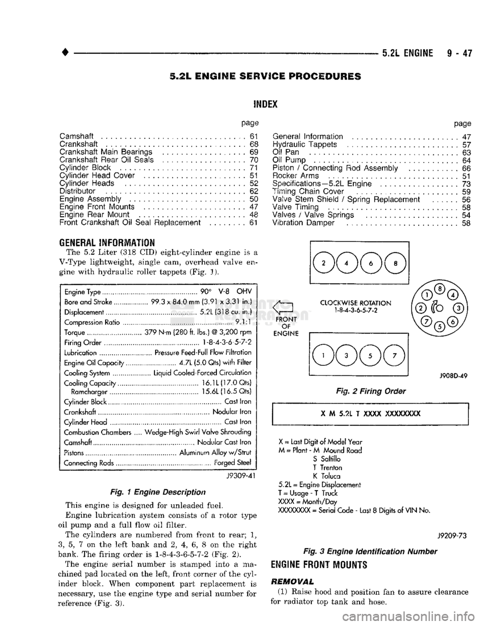
The 5.2 Liter (318 CID) eight-cylinder engine is a
V-Type lightweight, single cam, overhead valve en gine with hydraulic roller tappets (Fig. J).
Engine
Type ....
90° V-8 OHV
Bore
and Stroke .....
99.3
x
84.0 mm
(3.91
x
3.31
in.)
Displacement................
5.2L(318cu.
in.)
Compression
Ratio ....... .
9.1:1
Torque .. 379 N-m (280
ft.
lbs.)
@
3,200
rpm
Firing Order .... 1-8-4-3-6-5-7-2
Lubrication
.......
Pressure
Feed-Full Flow
Filtration
Engine
Oil
Capacity......
4.7L
(5.0 Qts)
with Filter
Cooling System ...... Liquid Cooled-Forced
Circulation
Cooling Capacity..........
16.1L(17.0Qts)
Ramcharger
15.6L
(16.5 Qts)
Cylinder Block
,
Cast
Iron
Crankshaft Nodular Iron
Cylinder Head ..............
Cast
Iron
Combustion Chambers
..
Wedge-High
Swirl Valve Shrouding
Camshaft Nodular Cast Iron
Pistons
Aluminum Alloy
w/Strut
Connecting
Rods...........
Forged
Steel
J9309-41
Fig. 1
Engine
Description
This engine is designed for unleaded fuel.
Engine lubrication system consists of a rotor type
oil pump and a full flow oil filter.
The cylinders are numbered from front to rear; 1?
3,
5, 7 on the left bank and 2, 4, 6, 8 on the right
bank. The firing order is 1-8-4-3-6-5-7-2 (Fig. 2).
The engine serial number is stamped into a ma
chined pad located on the left, front corner of the cyl
inder block. When component part replacement is
necessary, use the engine type and serial number for
reference (Fig. 3).
page
General
Information
.......................
47
Hydraulic Tappets
57
Oil
Pan . 63
Oil Pump
. 64
Piston
/
Connecting
Rod
Assembly
66
Rocker
Arms
51
Specifications—5.2L Engine
73
Timing Chain Cover ................
59
Valve Stem Shield
/
Spring Replacement
56
Valve Timing
. 58
Valves
/
Valve Springs
54
Vibration
Damper
. . 58
J908D-49
Fig.
2 Firing Order
X
M 5.2L T
XXXX
XXXXXXXX
X
~
Last Digit of
Model
Year
M
=
Plant
- M
Mound
Road
S
Saltillo
T
Trenton
K
Toluca
5.2L
=
Engine Displacement
T
=
Usage
-
T Truck
XXXX
=
Month/Day
XXXXXXXX
=
Serial Code
-
Last
8
Digits
of
VIN
No.
J9209-73
Fig.
3
Engine
Identification
Number
ENGINE
FRONT
MOUNTS
REMOVAL
(1) Raise hood and position fan to assure clearance
for radiator top tank and hose.
Page 682 of 1502
5.9L
ENGINE SERVICE PROCEDURES
INDEX
page
Camshaft
91
Crankshaft
98
Crankshaft Main Bearings
99
Crankshaft Rear
Oil
Seals
100
Cylinder
Block
101
Cylinder
Head Cover
81
Cylinder
Heads
82
Distributor
92
Engine Assembly
80
Engine
Front
Mounts
77
Engine Rear Mount
78
Front
Crankshaft
Oil
Seal Replacement
91
page
General
Information
77
Hydraulic
Tappets
87
Oil
Pan 93
Oil Pump
. 94
Piston
/
Connecting
Rod
Assembly
96
Rocker Arms
81
Specifications—5.9L
Engine
103
Timing
Chain Cover
89
Valve Stem Shield
/
Spring Replacement
86
Valve
Timing
. 88
Valves
/
Valve Springs
84
Vibration
Damper
88
GENERAL
INFORMATION
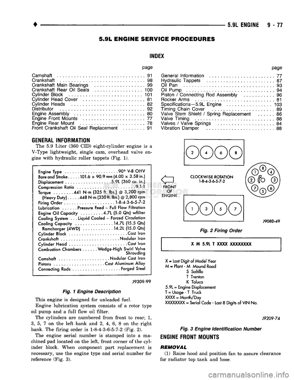
The 5.9 Liter (360 CID) eight-cylinder engine is a
V-Type lightweight, single cam, overhead valve en
gine with hydraulic roller tappets (Fig. 1).
Engine Type .90° V-8 OHV
Bore and Stroke 101.6 x 90.9
mm
(4.00 x 3.58 in.)
Displacement 5.9L (360 cu. in.)
Compression Ratio 9.1:1
Torque 441 N-m (325 ft. lbs.) @ 3,200 rpm (Heavy Duty). 448 N-m (330 ft. lbs.)
@
2,800 rpm
Firing Order
1-8-4-3-6-5-7-2
Lubrication ...... Pressure Feed - Full Flow Filtration
Engine Oil Capacity .4.7L (5.0 Qts) w/filter
Cooling System . .
.
Liquid Cooled - Forced Circulation Cooling Capacity ..... . . 14.7L (15.5 Qts)
Ramcharger (4WD) 14.2L (15.0 Qts)
Cylinder Block Cast Iron Crankshaft
-
Nodular Iron
Cylinder Head • . Cast Iron Combustion Chambers Wedge-High Swirl Valve
Shrouding
Camshaft Nodular Cast Iron Pistons Cast Aluminum Alloy
Connecting Rods Forged Steel
J9309-99
Fig. 1
Engine
Description
This engine is designed for unleaded fuel.
Engine lubrication system consists of a rotor type
oil pump and a full flow oil filter.
The cylinders are numbered from front to rear; 1,
3,
5, 7 on the left bank and 2, 4, 6, 8 on the right
bank. The firing order is
1-8-4-3-6-5-7-2
(Fig. 2).
The engine serial number is stamped into a ma
chined pad located on the left, front corner of the cyl
inder block. When component part replacement is
necessary, use the engine type and serial number for
reference (Fig. 3).
o
FRONT OF
ENGINE CLOCKWISE ROTATION
1-8-4-3-6-5-7-2
J908D-49
Fig. 2 Firing Order
X
M 5.9L T
XXXX
XXXXXXXX
X
= Last Digit of Model Year
M = Plant - M Mound Road S Saltillo
T Trenton K Toluca
5.9L = Engine Displacement
T
= Usage -
T
Truck
XXXX
= Month/Day
XXXXXXXX
= Serial Code - Last 8 Digits of
VIN
No.
J9209-74
Fig.
3
Engine
identification
Number
ENGINE
FRONT MOUNTS
REMOVAL (1) Raise hood and position fan to assure clearance
for radiator top tank and hose.
Page 712 of 1502
•
5.9L
(DIESEL)
ENGINE
9 -
107
5.9L
(DIESEL)
ENGINE
SERVICE
PROCEDURES
INDEX
page
Camshaft
127
Crankshaft
138
Cylinder
Block
129
Cylinder
Head
113
Engine
Assembly
. 109
Engine
Front
Mounts
(Insulators
/
Brackets)
... 107
Engine
Rear Support
108
Gear
Housing
/
Cover
122
General
Information
107
Oil Cooler Element
/
Gasket
. 149
Oil
Filter
148
page
Oil
Filter
Bypass
Valve
. 148
Oil Pan
/
Suction Tube
146
Oil Pressure Regulator Valve
/
Spring
148
Oil Pump
146
Piston
/
Connecting
Rod
Assembly
134
Rocker
Levers
/
Push
Rods
112
Specifications—5.9L Diesel Engines
151
Tappet
125
Timing
Pin
123
Valve Clearance
Adjustment
...............
121
Valves
and
Valve Springs
116
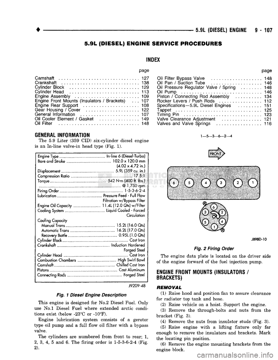
GENERAL INFORMATION The
5.9
Liter
(359 CID)
six-cylinder diesel engine
is
an
In-line valve-in head type
(Fig. 1).
Fig.
1
Diesel
Engine
Description
This engine
is
designed
for No.2
Diesel Fuel. Only
use
No.l
Diesel Fuel where extended arctic condi
tions exist (below -23°C
or -10°F).
Engine lubrication system consists
of a
gerotor
type
oil
pump
and a
full flow
oil
filter with
a
bypass valve.
The cylinders
are
numbered from front
to
rear;
1,
2,
3, 4, 5 and 6. The
firing order
is
1-5-3-6-2-4
(Fig.
2).
J898D-10
Fig.
2
Firing Order
The engine data plate
is
located
on the
driver side
of
the
engine forward
of the
fuel injection pump.
ENGINE FRONT MOUNTS (INSULATORS
/
BRACKETS)
REMOVAL (1) Raise hood
and
position
fan to
assure clearance
for radiator
top
tank
and
hose.
(2) Raise vehicle
on a
hoist. Support
the
engine.
(3) Remove
the
through-bolts
and
nuts from
the
bracket
(Fig. 3).
(4) Remove
the
nuts from insulator studs
(Fig. 3).
(5) Raise engine with
a
lifting fixture only
far
enough
to
remove
the
insulators
and
brackets. Mark
the locating
pin
position.
(6) Remove
the
engine mounting brackets from
the
engine block.
Engine Type
In-line
6
(Diesel-Turbo)
Bore and Stroke 102.0 x 120.0 mm
(4.02x4.72 in.)
Displacement 5.9L (359 cu.
in.)
Compression Ratio 17.5:1
Torque 542 N-m (400 ft. lbs.)
@
1,750 rpm
Firing Order
1-5-3-6-2-4
Lubrication Pressure Feed - Full Flow
Filtration w/Bypass Filter
Engine Oil Capacity
11.4L
(12.0 Qts) w/Filter
Cooling System Liquid Cooled
-
Forced
Circulation
Cooling Capacity
Manual Trans 15.2L (16.0 Qts)
Automatic Trans 16.2L (17.0 Qts)
Recovery Bottle 0.95L(1.0Qts)
Cylinder Block.... Cast Iron
Crankshaft Induction Hardened
Forged Steel
Cylinder Head Cast Iron
Combustion Chambers High Swirl Bowl
Camshaft.... Chilled Cast Iron
Pistons Cast Aluminum
Connecting Rods Forged Steel
J9209-48
Page 719 of 1502
9
- 114 5.9L
(DIESEL) ENGINE
—
Fig.
4
Exhaust
Manifold
(6) Remove the fuel lines and injector nozzles (re
fer to Group 14, Fuel System).
(7) Remove the valve covers (Fig. 5).
Fig.
5
Valve
Cover
(8) Remove the rocker levers and push rods.
(9) Remove the fuel/water separator filter (Fig. 6).
Refer to Group 14, Fuel System, for the proper pro
cedures.
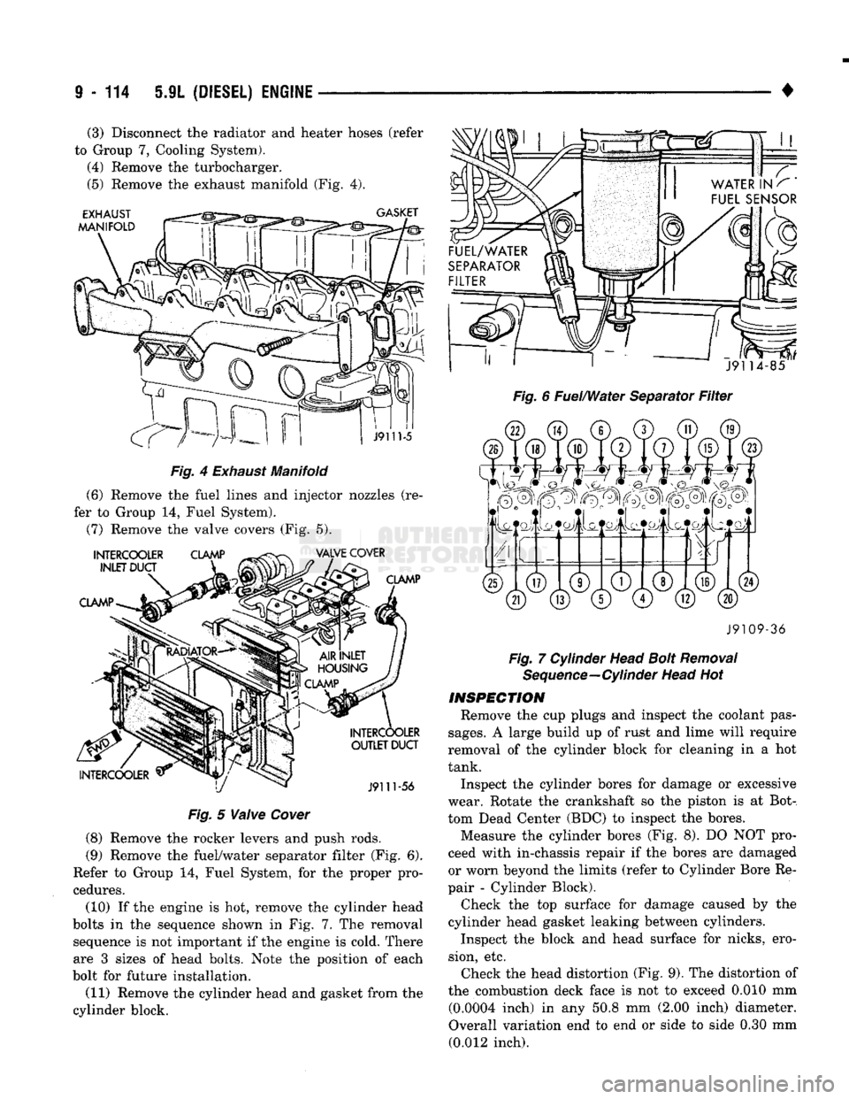
(10) If the engine is hot, remove the cylinder head
bolts in the sequence shown in Fig. 7..The removal sequence is not important if the engine is cold. There
are 3 sizes of head bolts. Note the position of each
bolt for future installation.
(11) Remove the cylinder head and gasket from the
cylinder block.
•
Fig. 6 Fuel/Water Separator Filter J9109-36
Fig. 7 Cylinder Head Bolt Removal Sequence—Cylinder Head Hot
INSPECTION
Remove the cup plugs and inspect the coolant pas
sages.
A large build up of rust and lime will require
removal of the cylinder block for cleaning in a hot
tank.
Inspect the cylinder bores for damage or excessive
wear. Rotate the crankshaft so the piston is at Bot
tom Dead Center (BDC) to inspect the bores. Measure the cylinder bores (Fig. 8). DO NOT pro
ceed with in-chassis repair if the bores are damaged
or worn beyond the limits (refer to Cylinder Bore Re
pair - Cylinder Block).
Check the top surface for damage caused by the
cylinder head gasket leaking between cylinders.
Inspect the block and head surface for nicks, ero
sion, etc. Check the head distortion (Fig. 9). The distortion of
the combustion deck face is not to exceed 0.010 mm (0.0004 inch) in any 50.8 mm (2.00 inch) diameter.
Overall variation end to end or side to side 0.30 mm (0.012 inch).
(3) Disconnect the radiator and heater hoses (refer
to Group 7, Cooling System). (4) Remove the turbocharger.
(5) Remove the exhaust manifold (Fig. 4).
Page 817 of 1502
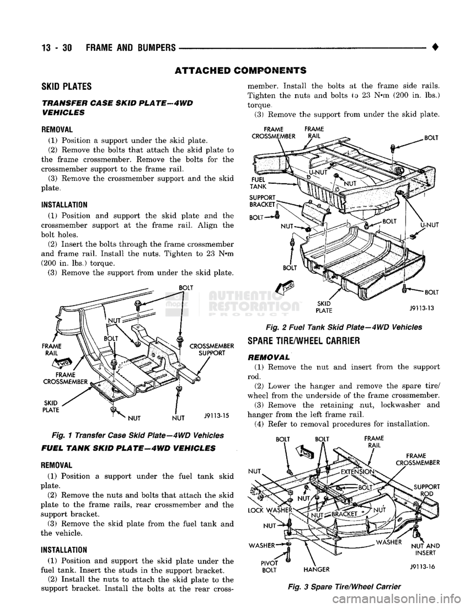
13
- 30 FRAME AND BUMPERS
ATTACHED COMPONENTS
SKID
PLATES
TRANSFER CASE SKID
PL
ATF
4 WD
VEHICLES
REMOVAL
(1) Position
a
support under
the
skid plate.
(2) Remove
the
bolts that attach
the
skid plate
to
the frame crossmember. Remove
the
bolts
for the
crossmember support
to the
frame rail.
(3) Remove
the
crossmember support
and the
skid
plate.
INSTALLATION
(1) Position
and
support
the
skid plate
and the
crossmember support
at the
frame rail. Align
the
bolt holes.
(2) Insert
the
bolts through
the
frame crossmember
and frame rail. Install
the
nuts. Tighten
to 23 N*m
(200
in. lbs.)
torque.
(3) Remove
the
support from under
the
skid plate.
Fig.
1
Transfer
Case Skid
Plate—4WD Vehicles
FUEL TANK SKID
PLATE-4WD
VEHICLES
REMOVAL
(1) Position
a
support under
the
fuel tank skid
plate.
(2) Remove
the
nuts
and
bolts that attach
the
skid
plate
to the
frame rails, rear crossmember
and the
support bracket.
(3) Remove
the
skid plate from
the
fuel tank
and
the vehicle.
INSTALLATION
(1) Position
and
support
the
skid plate under
the
fuel tank. Insert
the
studs
in the
support bracket.
(2) Install
the
nuts
to
attach
the
skid plate
to the
support bracket. Install
the
bolts
at the
rear cross- member. Install
the
bolts
at the
frame side rails.
Tighten
the
nuts
and
bolts
to 23 N*m (200 in. lbs.)
torque.
(3) Remove
the
support from under
the
skid plate.
FRAME FRAME
Fig.
2
Fuel
Tank
Skid
Plate-4WD Vehicles
SPARE
TIRE/WHEEL
CARRIER
REMOVAL
(1) Remove
the nut and
insert from
the
support
rod. (2) Lower
the
hanger
and
remove
the
spare tire/
wheel from
the
underside
of the
frame crossmember.
(3) Remove
the
retaining
nut,
lockwasher
and
hanger from
the
left frame rail.
(4) Refer
to
removal procedures
for
installation. BOLT BOLT FRAME
Fig.
3
Spare
The/Wheel Carrier
Page 820 of 1502
•
FUEL
SYSTEM
14 - 1
FUEL
SYSTEM
page
ACCELERATOR
PEDAL
AND THROTTLE
CABLE
................ 25
DIESEL
FUEL
INJECTION-COMPONENT
DESCRIPTION/SYSTEM
OPERATION
76
DIESEL
FUEL
INJECTION-GENERAL
DIAGNOSIS
88
DIESEL
FUEL
INJECTION-SERVICE
PROCEDURES
....................... 106
FUEL
DELIVERY
SYSTEM-EXCEPT
DIESEL
.. 3
FUEL
DELIVERY-DIESEL
ENGINE
15
FUEL
TANKS
.... 20
page
GENERAL
INFORMATION 1
MULTI-PORT
FUEL
INJECTION (MPI)-
COMPONENT
DESCRIPTION/SYSTEM
OPERATION-EXCEPT
DIESEL
29
MULTI-PORT
FUEL
INJECTION (MPI)-
COMPONENT
REMOVAL/INSTALLATION-
EXCEPT
DIESEL
64
MULTI-PORT
FUEL
INJECTION (MPI)-
GENERAL
DIAGNOSIS-EXCEPT
DIESEL
...43
SERVICE
ADJUSTMENTS-DIESEL
122
SPECIFICATIONS
123
GENERAL INFORMATION
Throughout this group, references are made to par
ticular vehicle models by alphabetical designation or
by the particular vehicle nameplate. A chart showing a breakdown of the alphabetical designations is in
cluded in the Introduction section at the beginning of
this manual.
The 5.9L (V-8) gas powered engine will be referred
to in this group as either the: LDC (Light Duty Cy cle) or HDC (Heavy Duty Cycle) engine. The HDC engine can be easily identified by the use of an en
gine mounted air injection pump. The 3.9L/5.2L/5.9L
LDC engine will not use an air injection pump.
This Fuel System group will cover all fuel system
components for the 3.9L (V-6), 5.2L (V-8), 5.9L LDC
(V-8),
5.9L HDC (V-8) and 5.9L (in-line six cylinder)
diesel engines.
The Fuel System consists of: the fuel tank, an
electric (fuel tank mounted) fuel pump and fuel fil
ter. It also consists of fuel tubes/lines/hoses, vacuum
hoses,
throttle body and fuel injector(s).
The Fuel Delivery System consists of: the electric
fuel pump, fuel filter, fuel tubes/lines/hoses, fuel rail,
fuel injectors and fuel pressure regulator.
A Fuel Return System is used on all vehicles (all
engines) except the 5.9L (V-8) gas powered engine. On this engine, a returnless type fuel system is
used. The fuel return system consists of fuel tubes/
lines and hoses that route fuel back to the fuel tank.
The Fuel Tank Assembly consists of: the fuel
tank, filler tube, fuel gauge sending unit/electric fuel
pump module, a pressure relief/rollover valve and a
pressure-vacuum filler cap. Also to be considered part of the fuel system is the
Evaporation Control System. This is designed to
reduce the emission of fuel vapors into the atmo sphere. The description and function of the Evapora
tive Control System is found in Group 25, Emission Control Systems.
FUEL
USAGE
STATEMENT-GAS
ENGINES
Your vehicle was designed to meet all emission
regulations and provide excellent fuel economy using
high quality unleaded gasoline. Only use unleaded gasolines having a minimum posted octane of 87. If your vehicle develops occasional light spark
knock (ping) at low engine speeds, this is not harm
ful.
However, continued heavy knock at high speeds can cause damage and should be re
ported to your dealer immediately. Engine dam age as a result of heavy knock operation may not be
covered by the new vehicle warranty. In addition to using unleaded gasoline with the
proper octane rating, those that contain deter
gents,
corrosion and stability additives are rec
ommended. Using gasolines that have these additives will help improve fuel economy, reduce
emissions and maintain vehicle performance. Gener ally, premium unleaded gasolines contain more addi
tive than regular unleaded gasolines. Poor quality gasoline can cause problems such as
hard starting, stalling and stumble. If you experience
these problems, use another brand of gasoline before considering service for the vehicle.
Page 823 of 1502
14-4
FUEL
SYSTEM
•
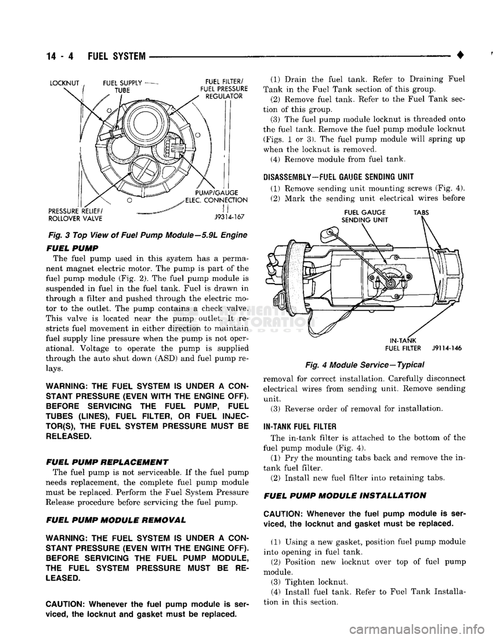
Fig.
3 Top View of
Fuel
Pump
Module—5.9L
Engine
FUEL
PUMP
The fuel pump used in this system has a perma
nent magnet electric motor. The pump is part of the
fuel pump module (Fig. 2). The fuel pump module is suspended in fuel in the fuel tank. Fuel is drawn in
through a filter and pushed through the electric mo
tor to the outlet. The pump contains a check valve.
This valve is located near the pump outlet. It re stricts fuel movement in either direction to maintain
fuel supply line pressure when the pump is not oper ational. Voltage to operate the pump is supplied
through the auto shut down (ASD) and fuel pump re
lays.
WARNING:
THE
FUEL SYSTEM
IS
UNDER
A
CON STANT PRESSURE (EVEN
WITH
THE
ENGINE OFF).
BEFORE
SERVICING
THE
FUEL PUMP, FUEL
TUBES
(LINES), FUEL FILTER,
OR
FUEL
INJEC
TOR^),
THE
FUEL SYSTEM PRESSURE MUST
BE
RELEASED.
FUEL
PUMP
REPLACEMENT
The fuel pump is not serviceable. If the fuel pump
needs replacement, the complete fuel pump module must be replaced. Perform the Fuel System Pressure
Release procedure before servicing the fuel pump.
FUEL
PUMP
MODULE
REMOVAL
WARNING:
THE
FUEL SYSTEM
IS
UNDER
A
CON STANT PRESSURE (EVEN
WITH
THE
ENGINE OFF).
BEFORE
SERVICING
THE
FUEL PUMP MODULE,
THE FUEL SYSTEM PRESSURE MUST
BE RE
LEASED.
CAUTION:
Whenever
the
fuel
pump
module
is
ser
viced,
the
locknut
and gasket
must
be replaced. (1) Drain the fuel tank. Refer to Draining Fuel
Tank in the Fuel Tank section of this group.
(2) Remove fuel tank. Refer to the Fuel Tank sec
tion of this group.
(3) The fuel pump module locknut is threaded onto
the fuel tank. Remove the fuel pump module locknut
(Figs.
1 or 3). The fuel pump module will spring up
when the locknut is removed.
(4)
Remove module from fuel tank.
DISASSEMBLY-
FUEL GAUGE SENDING
UNIT
(1) Remove sending unit mounting screws (Fig. 4).
(2) Mark the sending unit electrical wires before
FUEL
GAUGE
TABS
IN-TANK
FUEL
FILTER
J9114-146
Fig.
4
Module
Service—Typical
removal for correct installation. Carefully disconnect electrical wires from sending unit. Remove sending unit.
(3) Reverse order of removal for installation.
IN-TANK FUEL FILTER
The in-tank filter is attached to the bottom of the
fuel pump module (Fig. 4).
(1) Pry the mounting tabs back and remove the in-
tank fuel filter.
(2) Install new fuel filter into retaining tabs.
FUEL
PUMP
MODULE
INSTALLATION
CAUTION:
Whenever
the
fuel
pump
module
is
ser
viced,
the
locknut
and
gasket must
be
replaced.
(1) Using a new gasket, position fuel pump module
into opening in fuel tank. (2) Position new locknut over top of fuel pump
module. (3) Tighten locknut. (4) Install fuel tank. Refer to Fuel Tank Installa
tion in this section.