1993 DODGE TRUCK ESP
[x] Cancel search: ESPPage 15 of 1502
10 INTRODUCTION
•
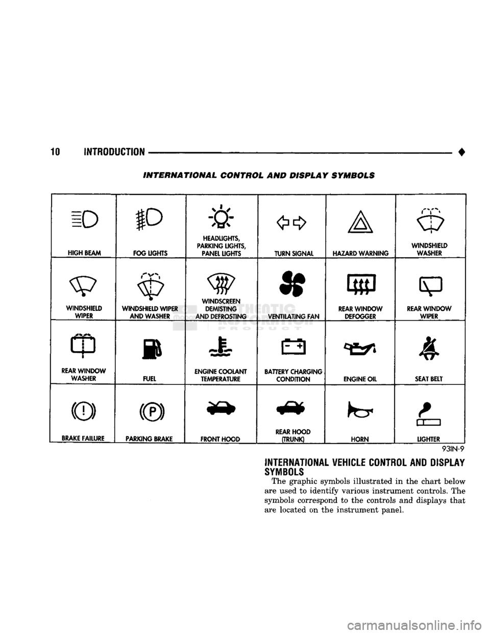
INTERNATIONAL CONTROL AND DISPLAY SYMBOLS
ID
HIGH
BEAM P
FOG UGHTS -&
HEADLIGHTS,
PARKING UGHTS, PANEL UGHTS TURN SIGNAL A
HAZARD WARNING WINDSHIELD
WASHER
WINDSHIELD WIPER WINDSHIELD WIPER
AND WASHER
AND DEFROSTING *
VENTILATING
FAN 8
M f
REAR
WINDOW DEFOGGER
sp
REARWINLX)W WIPER
CD
l
m
REAR
WINDOW WASHER FUEL ENGINE COOLANT
TEMPERATURE BATTERY CHARGING
CONDITION ENGINE OIL
SEAT
BELT
(©) (®) ky
11 J
LIGHTER
BRAKE
FAILURE
PARKING
BRAKE
FRONT HOOD
REAR
HOOD
(TRUNK)
HORN
11 J
LIGHTER
93IN-9
INTERNATIONAL VEHICLE CONTROL AND DISPLAY
SYMBOLS
The graphic symbols illustrated in the chart below
are used to identify various instrument controls. The
symbols correspond to the controls and displays that are located on the instrument panel.
Page 16 of 1502
•
INTRODUCTION
11
MEASUREMENT
AND
TORQUE SPECIFICATIONS
INDEX
page
Metric
and
English/SAE
Conversion
11
Specification
Notations
11
SPECIFICATION NOTATIONS
WARNING:
THE USE OF
INCORRECT
ATTACHING
HARDWARE
CAN
RESULT
IN
COMPONENT
DAM
AGE
AND/OR
PERSONAL
INJURY.
It is important to retain the original attaching
hardware for assembly of the components. If the at
taching hardware is not reusable, hardware with
equivalent specifications must be used.
METRIC
AND
ENGLISH/SAE
CONVERSION
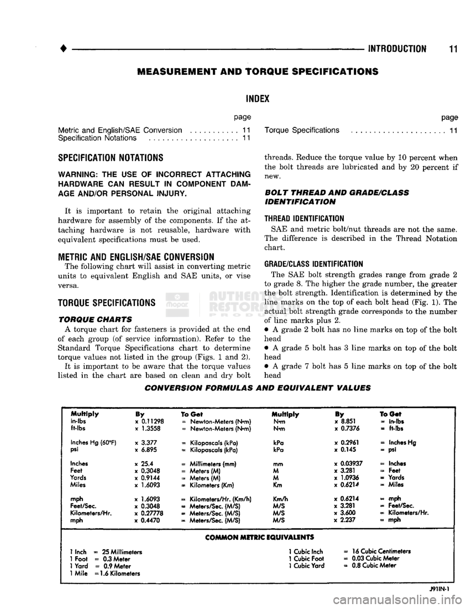
The following chart will assist in converting metric
units to equivalent English and SAE units, or vise versa.
TORQUE SPECIFICATIONS
TORQUE
CHARTS
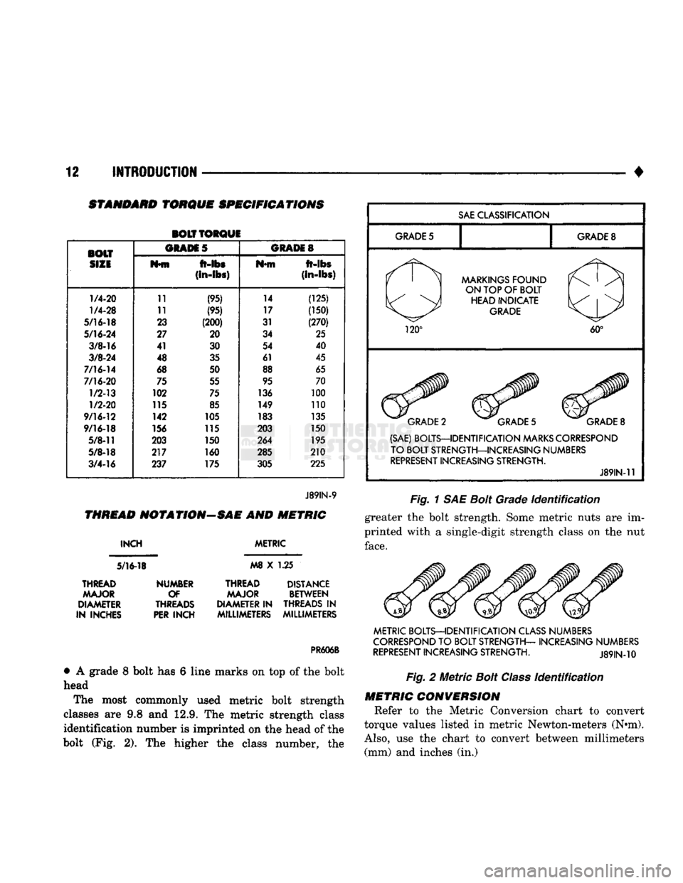
A torque chart for fasteners is provided at the end
of each group (of service information). Refer to the Standard Torque Specifications chart to determine
torque values not listed in the group (Figs. 1 and 2).
It is important to be aware that the torque values
listed in the chart are based on clean and dry bolt
page
Torque Specifications
11
threads. Reduce the torque value by 10 percent when the bolt threads are lubricated and by 20 percent if new.
BOLT
THREAD
AND
GRADE/CLASS
IDENTIFICATION
THREAD
IDENTIFICATION
SAE and metric bolt/nut threads are not the same.
The difference is described in the Thread Notation chart.
GRADE/CLASS
IDENTIFICATION
The SAE bolt strength grades range from grade 2
to grade 8. The higher the grade number, the greater
the bolt strength. Identification is determined by the line marks on the top of each bolt head (Fig. 1). The
actual bolt strength grade corresponds to the number
of line marks plus 2.
• A grade 2 bolt has no line marks on top of the bolt
head
• A grade 5 bolt has 3 line marks on top of the bolt
head • A grade 7 bolt has 5 line marks on top of the bolt
head
CONVERSION FORMULAS
AND
EQUIVALENT
VALUES
Multiply
in-lbs
ft-lbs
By
x
0.11298
x
1.3558
To
Get
=
Newton-Meters (N*m)
=
Newton-Meters (N*m) Multiply
N*m
iy
x
8.851
x
0.7376
BGef
-
in-fbs
-
ft-lbs
Inches
Hg
(60°F)
psi
x
3.377
x
6.895
=
Kilopascals
(kPa)
=
Kilopascals
(kPa)
kPa
kPa
x
0.2961
x
0.145
«
Inches
Hg
- psi
Inches
Feet
Yards
Miles
x 25.4
x
0.3048
x
0.9144
x
1.6093
« Millimeters (mm)
=
Meters (M)
-
Meters (M)
=
Kilometers (Km) mm
M
M
Km
x
0.03937
x
3.281
x
1.0936
x
0.6214
« Inches
-
Feet
=
Yards « Miles
mph
Feet/Sec.
Kilometers/Hr.
mph
x
1.6093
x
0.3048
x
0.27778
x
0.4470
=
Kilometers/Hr. (Km/h)
«
Meters/Sec.
(M/S)
«
Meters/Sec.
(M/S)
=
Meters/Sec.
(M/S)
Km/h
M/S
M/S
M/S
x
0.6214
x
3.281
x
3.600
x
2.237 - mph
=
Feet/Sec.
=
Kilometers/Hr.
» mph
COMMON
MITRIC
EQUIVALENTS
1
Inch
=
25 Millimeters
1
Cubic
Inch
»
16
Cubic
Centimeters
1
Foot
-
0.3 Meter
1
Cubic
Foot
«
0.03
Cubic
Meter
1
Yard
=
0.9 Meter
1
Cubic
Yard
=
0.8
Cubic
Meter
1
Mile =1.6 Kilometers
J91IN-1
Page 17 of 1502
12
INTRODUCTION
STANDARD
TORQUE
SPECIFICATIONS
BOLT TORQUE
BOLT ORAM
5
GRADES
SIZE
M*fn
ft-lbs
Nfft
ft-abs
(in-lbs)
(In-lbs)
1/4-20
11
(95) 14
(125)
1/4-28
11 (95) 17 (150)
5/16-18
23 (200) 31 (270)
5/16-24
27 20 34 25
3/8-16
41
30 54
40
3/8-24
48 35 61 45
7/16-14
68
50 88 65
7/16-20
75 55 95 70
1/2-13
102
75 136 100
1/2-20
115 85 149 110
9/16-12
142
105 183 135
9/16-18
156 115 203 150
5/8-11
203 150 264 195
5/8-18
217 160 285 210
3/4-16
237 175
305 225
J89IN-9
THREAD
NOT A
TION—SAE
AND
METRIC
INCH
5/16-18
METRIC
M8
X 1.25
THREAD MAJOR
DIAMETER
IN INCHES NUMBER
OF
THREADS
PER
INCH
THREAD DISTANCE
MAJOR BETWEEN
DIAMETER IN THREADS
IN
MILLIMETERS MILLIMETERS
PR606B
•
A grade 8 bolt has 6 line marks on top of the bolt
head
The most commonly used metric bolt strength
classes are 9.8 and 12.9. The metric strength class identification number is imprinted on the head of the
bolt (Fig. 2). The higher the class number, the
SAE
CLASSIFICATION
GRADE
5
GRADE
8
MARKINGS
FOUND
ON TOP OF BOLT HEAD INDICATE
GRADE
120°
60°
GRADE
2
GRADE
5
GRADE
8
(SAE) BOLTS—IDENTIFICATION
MARKS
CORRESPOND
TO BOLT STRENGTH—INCREASING NUMBERS
REPRESENT
INCREASING STRENGTH.
J89IN-11
Fig.
1 SAE
Bolt
Grade
Identification
greater the bolt strength. Some metric nuts are im
printed with a single-digit strength class on the nut
face.
METRIC BOLTS—IDENTIFICATION
CLASS
NUMBERS
CORRESPOND
TO BOLT STRENGTH— INCREASING NUMBERS
REPRESENT
INCREASING STRENGTH.
J89IN-10
Fig.
2
Metric
Bolt
Class
Identification
METRIC
CONVERSION
Refer to the Metric Conversion chart to convert
torque values listed in metric Newton-meters (N»m).
Also,
use the chart to convert between millimeters (mm) and inches (in.)
Page 20 of 1502
•
• —
LUiRICATlON
AND
MAINTENANCE
0 - 1
CONTENTS
page
page
CHASSIS
AND
BODY
28
ENGINE MAINTENANCE
14
DRIVETRAIN
.,,, 22
GENERAL INFORMATION
1
GENERAL
INFORMATION INDEl
page
Classification
of
Lubricants
. 3
Components
Requiring
No
Lubrication
4
Fuel Requirements
. 2
Introduction
1
Lubrication
and
Replacement Parts Recommendation
3
page
Routine Maintenance
2
Starting
Assistance (Jump Starting)
9
Vehicle
Lifting
Recommendations
............ 10
Vehicle Noise
Control
2
Vehicle Towing Recommendations
11
INTRODUCTION
Lubrication and maintenance is divided into re
quired and recommended service tasks. The required service tasks must be completed to verify the emis
sion controls function correctly. The recommended
service tasks should be completed to maintain safety
and durability. This information will assist the service personnel
in providing maximum protection for each owner's
vehicle. Conditions can vary with individual driving habits.
It is necessary to schedule maintenance as a time in
terval as well as a distance interval. It is the owner's responsibility to determine the ap
plicable driving condition. Also to have the vehicle serviced according to the maintenance schedule, and
to pay for the necessary parts and labor. Vehicles with a Gross Vehicle Weight Rating
(GVWR) of 3 855 kg (8,500 lbs.) or less must conform
to light duty emission standards. Vehicles with a Gross Vehicle Weight Rating (GVWR) of 3 856 kg
(8,501 lbs.) or more must conform to heavy duty
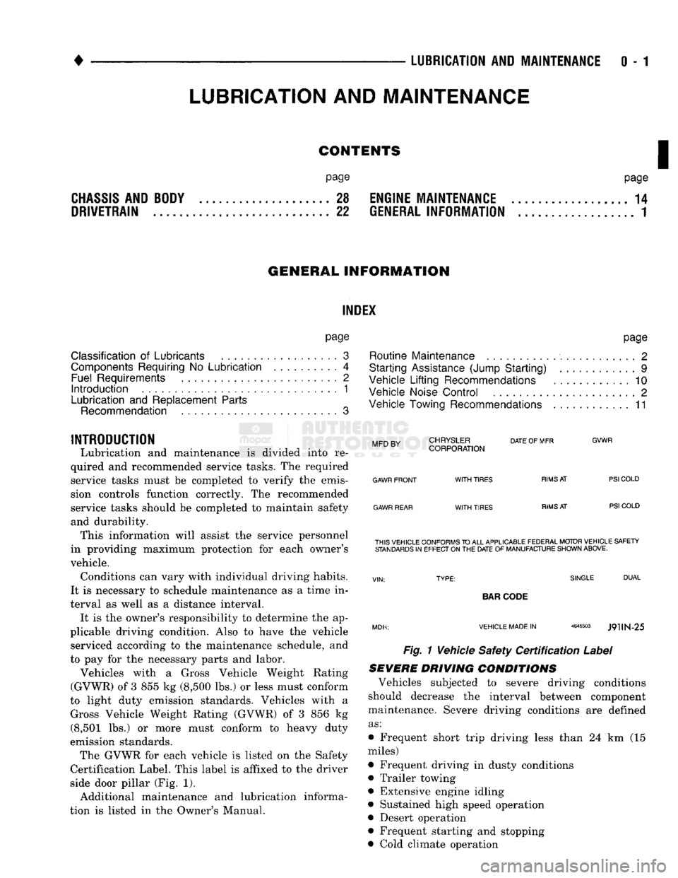
emission standards. The GVWR for each vehicle is listed on the Safety
Certification Label. This label is affixed to the driver
side door pillar (Fig. 1).
Additional maintenance and lubrication informa
tion is listed in the Owner's Manual.
Mm
rv
CHRYSLER
DATE
OF MFR
MFD BY CORPORATION
GVWR
GAWR FRONT
GAWR REAR
WITH
TIRES
WITH
TIRES
RIMS
AT
RIMS
AT
PSI
COLD
PSI
COLD THIS VEHICLE CONFORMS
TO
ALL APPLICABLE FEDERAL MOTOR VEHICLE SAFETY
STANDARDS
IN
EFFECT ON
THE
DATE
OF
MANUFACTURE SHOWN ABOVE.
SINGLE
DUAL
BAR
CODE
VEHICLE MADE
IN
4648503
J9UN-25
Fig. 1 Vehicle Safety
Certification
Label
SEVERE DRIVING
CONDITIONS
Vehicles subjected to severe driving conditions
should decrease the interval between component
maintenance. Severe driving conditions are defined
as:
• Frequent short trip driving less than 24 km (15
miles)
• Frequent driving in dusty conditions
• Trailer towing
• Extensive engine idling
• Sustained high speed operation
• Desert operation
• Frequent starting and stopping
• Cold climate operation
LUBRICATION
AND
MAINTENANCE
Page 59 of 1502
2
- 6
FRONT
SUSPENSION
AND
AXLE
•
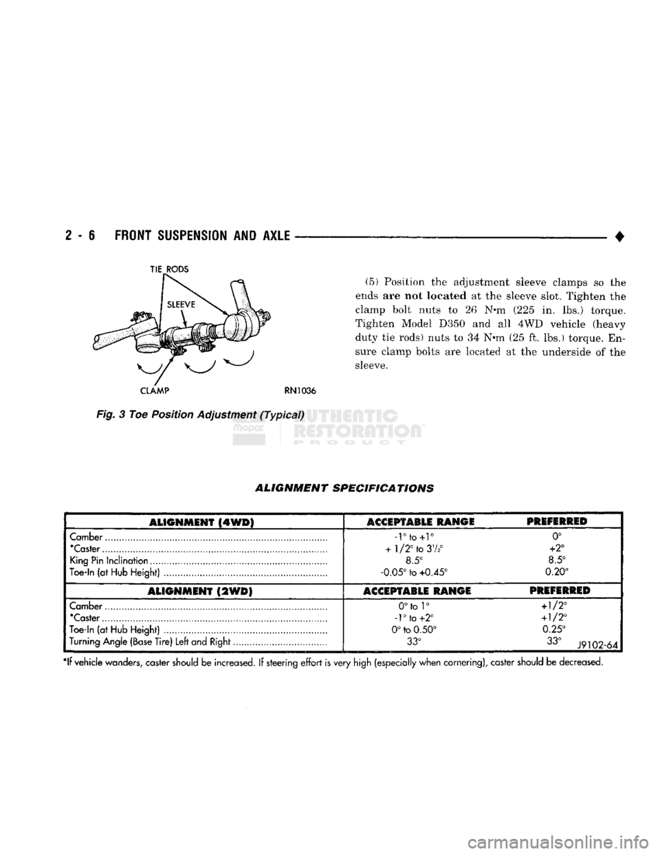
(5) Position the adjustment sleeve clamps so the
ends are not located at the sleeve slot. Tighten the
clamp bolt nuts to 26 N*m (225 in. lbs.) torque.
Tighten Model D350 and all 4WD vehicle (heavy
duty tie rods) nuts to 34 N*m (25 ft. lbs.) torque. En
sure clamp bolts are located at the underside of the
sleeve.
CLAMP
RN1036
Fig.
3 Toe Position Adjustment
(Typical)
ALIGNMENT
SPECIFICATIONS
ALIGNMENT
(4WD)
ASGSPTABLE RANGE
PREFERRED
Camber
-rto+r
0°
"Caster
+
1/2°
to
37*°
+2°
King
Pin
Inclination
8.5° 8.5°
Toe-In
(at
Hub
Height)
-0.05°
to
+0.45° 0.20°
ALIGNMENT
(2WD)
ACCEPTABLE RANGE PREFERRED
Camber
0°to 1°
+1/2°
'Caster
-1°
to
+2°
+1/2°
Toe-in
(at
Hub
Height)
0°
to
0.50° 0.25°
Turning
Angle
(Base
Tire)
Left
and
Right
33°
33°
J9102-64
*lf vehicle
wanders,
caster
should
be increased. If steering
effort
is very
high
(especially when cornering), caster
should
be decreased.
TIE
RODS
Page 63 of 1502
2
- 10
FRONT SUSPENSION
AND
AXLE
• INSTALLATION
(1) Position the spring and isolation pad on the
suspension arm. Install the spring compressor tool.
Compress the spring until the lower suspension arm
can be properly positioned in the steering knuckle.
(2) Install the nuts on the ball studs. Tighten the
upper nut to 142 Nnn (105 ft. lbs.) torque. Tighten
the lower nut.
* 11/16-16 bolt, to 183 Nnn (135 ft. lbs.) torque
• 3/4-16 bolt, to 237 Nnn (175 ft. lbs.) torque Install replacement cotter pins.
(3) Install the strut.
(4) Connect the stabilizer bar.
(5) Install the shock absorber.
(6) Install the brake splash shield on the steering
knuckle. Tighten the screws to 23 Nnn (200 in. lbs.)
torque.
(7) Carefully install the hub/rotor and bearings.
(8) Install the brake caliper, refer to Group 5, Brakes.
(9) Install the wheel and tire, refer to Wheel and Tire
Installation within this section. Lower the vehicle. (10) Test the vehicle brakes and the suspension for
proper operation.
LOWER SUSPENSION
ARM
REMOVAL
(1) Follow procedure under Coil Spring Removal.
(2) Remove hex-head mounting bolt from the cross-
member. (3) Remove the lower suspension arm from vehicle.
INSTALLATION (1) Position lower suspension arm on vehicle.
(2) Install mounting bolt, tighten finger-tight.
(3) Follow procedure under Coil Spring Installa
tion.
(4) Lower the vehicle to the surface with the
wheels/tires supporting the vehicle weight. Tighten
the lower suspension arm mounting bolt to 305 Nnn (225 ft. lbs.) torque.
LOWER
BALL
STUD
INSPECTION
(1) Raise the front of the vehicle. Install safety
floor stands under both lower suspension arms as far outboard as possible. The upper suspension arms
must not contact the rebound bumpers. (2) Install a dial indicator and clamp assembly to
the lower suspension arm. (3) Position indicator plunger against knuckle arm
and zero indicator. (4) Raise and lower the wheel with a pry bar under
the center of the tire. Measure the axial movement of
the knuckle with respect to the suspension arm.
(5) If the travel of the suspension arm is 0.020
inch (0.51 mm) or more, replace the ball joint. REMOVAL
(1) Follow procedure under Coil Spring Removal.
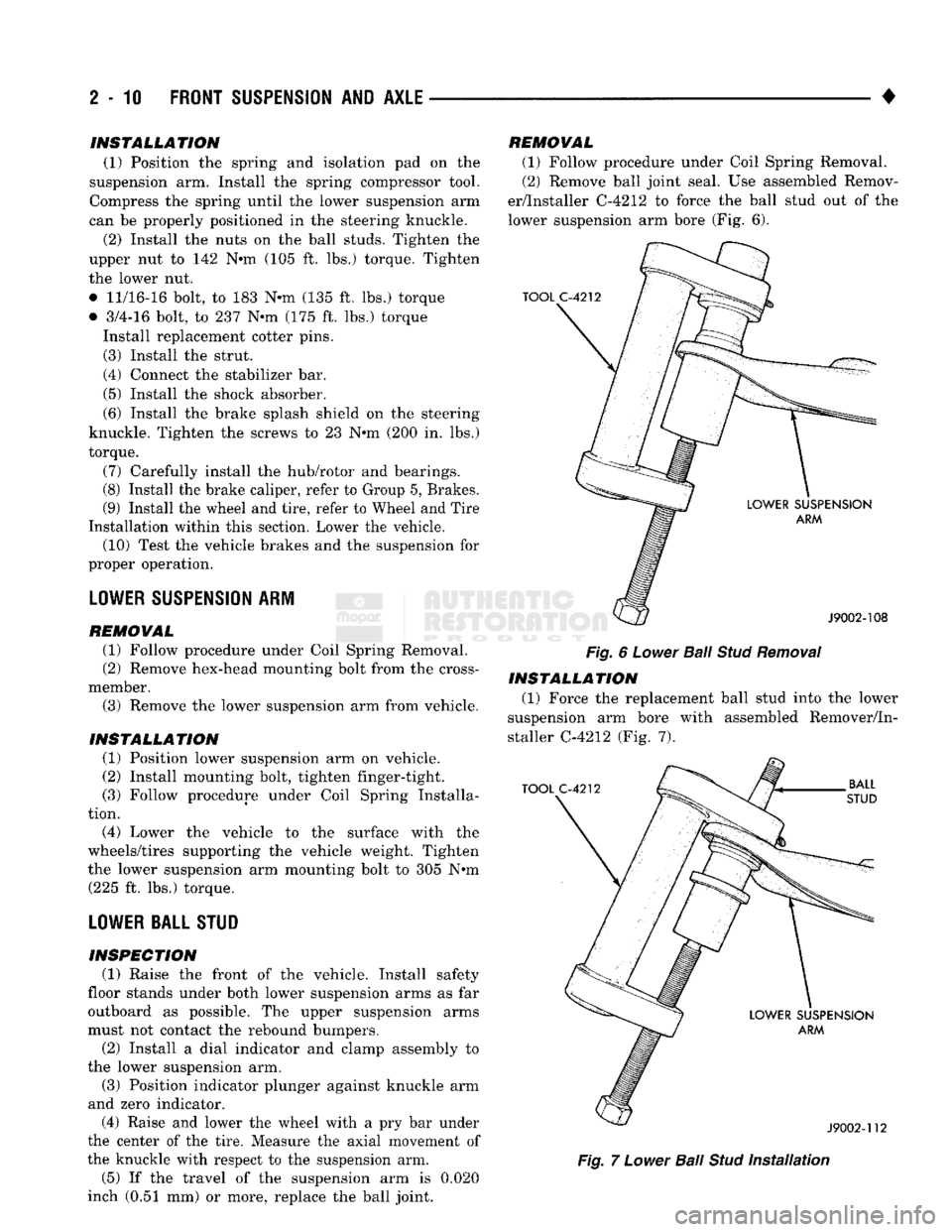
(2) Remove ball joint seal. Use assembled Remov
er/Installer C-4212 to force the ball stud out of the
lower suspension arm bore (Fig. 6).
Fig.
6
Lower
Bail
Stud
Removal
INSTALLATION (1) Force the replacement ball stud into the lower
suspension arm bore with assembled Remover/In
staller C-4212 (Fig. 7).
Fig.
7
Lower
Ball
Stud
Installation
Page 144 of 1502
REAR SUSPENSION
ANi
AXLE
3 - 17
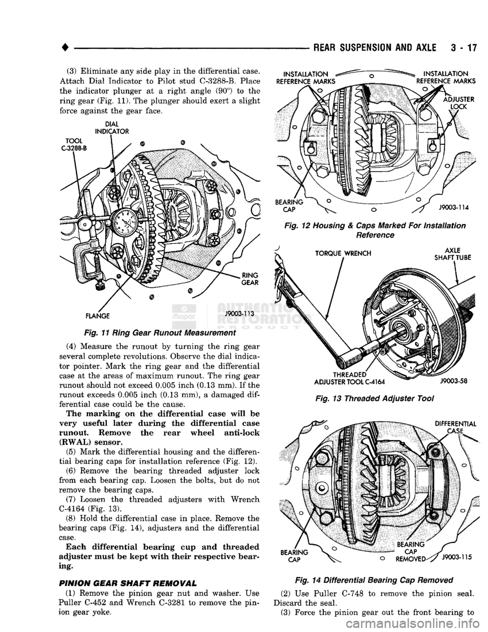
(3) Eliminate any side play in the differential case.
Attach Dial Indicator to Pilot stud C-3288-B. Place
the indicator plunger at a right angle (90°) to the ring gear (Fig. 11). The plunger should exert a slight
force against the gear face.
DIAL
INDICATOR
Fig.
11
Ring
Gear
Runout
Measurement
(4) Measure the runout by turning the ring gear
several complete revolutions. Observe the dial indica
tor pointer. Mark the ring gear and the differential
case at the areas of maximum runout. The ring gear
runout should not exceed 0.005 inch (0.13 mm). If the
runout exceeds 0.005 inch (0.13 mm), a damaged
dif
ferential case could be the cause.
The marking on the differential case will be
very useful later during the differential case
runout. Remove the rear wheel anti-lock (RWAL) sensor.
(5) Mark the differential housing and the differen
tial bearing caps for installation reference (Fig. 12).
(6) Remove the bearing threaded adjuster lock
from each bearing cap. Loosen the bolts, but do not
remove the bearing caps.
(7) Loosen the threaded adjusters with Wrench
C-4164 (Fig. 13).
(8) Hold the differential case in place. Remove the
bearing caps (Fig. 14), adjusters and the differential
case.
Each differential bearing cup and threaded
adjuster must be kept with their respective bear
ing.
PINION
GEAR
SHAFT
REMOVAL
(1) Remove the pinion gear nut and washer. Use
Puller C-452 and Wrench C-3281 to remove the pin
ion gear yoke.
Fig.
12
Housing
&
Caps
Marked For
Installation
Reference
Fig.
13 Threaded Adjuster Tool
Fig.
14
Differential
Bearing Cap
Removed
(2) Use Puller C-748 to remove the pinion seal.
Discard the seal. (3) Force the pinion gear out the front bearing to
Page 151 of 1502
3
- 24
REAR SUSPENSION
AND
AXLE
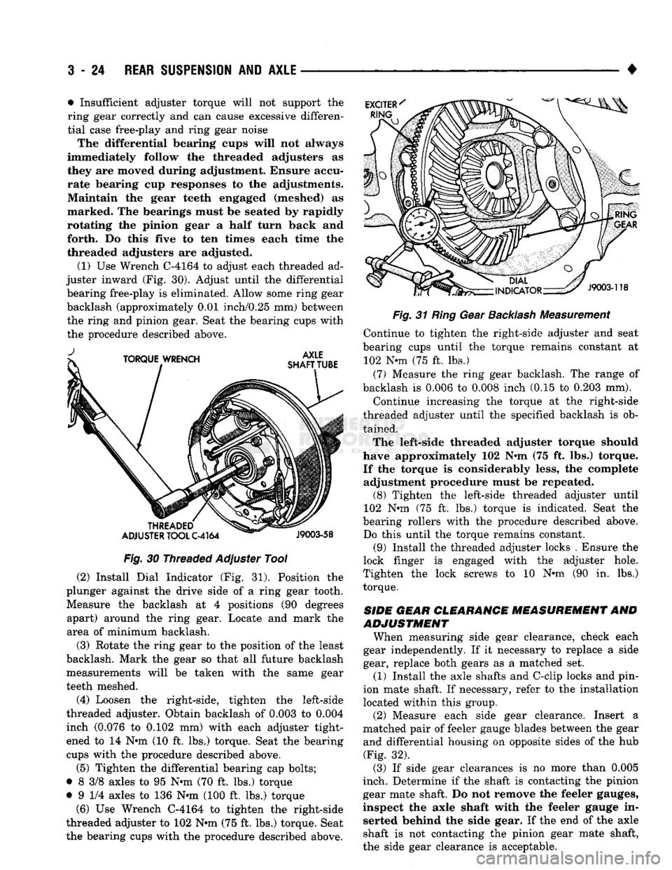
Fig.
30 Threaded Adjuster Tool
(2) Install Dial Indicator (Fig. 31). Position the
plunger against the drive side of a ring gear tooth. Measure the backlash at 4 positions (90 degrees apart) around the ring gear. Locate and mark the
area of minimum backlash.
(3) Rotate the ring gear to the position of the least
backlash. Mark the gear so that all future backlash
measurements will be taken with the same gear
teeth meshed.
(4) Loosen the right-side, tighten the left-side
threaded adjuster. Obtain backlash of 0.003 to 0.004
inch (0.076 to 0.102 mm) with each adjuster tight
ened to 14 N-m (10 ft. lbs.) torque. Seat the bearing
cups with the procedure described above.
(5) Tighten the differential bearing cap bolts;
• 8 3/8 axles to 95 N-m (70 ft. lbs.) torque
• 9 1/4 axles to 136 N-m (100 ft. lbs.) torque
(6) Use Wrench C-4164 to tighten the right-side
threaded adjuster to 102 N-m (75 ft. lbs.) torque. Seat the bearing cups with the procedure described above. •
Fig.
31
Ring
Gear
Backlash
Measurement Continue to tighten the right-side adjuster and seat
bearing cups until the torque remains constant at 102 N-m (75 ft. lbs.)
(7) Measure the ring gear backlash. The range of
backlash is 0.006 to 0.008 inch (0.15 to 0.203 mm).
Continue increasing the torque at the right-side
threaded adjuster until the specified backlash is ob tained.
The left-side threaded adjuster torque should
have approximately 102 N-m (75 ft. lbs.) torque. If the torque is considerably less, the complete adjustment procedure must be repeated. (8) Tighten the left-side threaded adjuster until
102 N-m (75 ft. lbs.) torque is indicated. Seat the
bearing rollers with the procedure described above. Do this until the torque remains constant. (9) Install the threaded adjuster locks . Ensure the
lock finger is engaged with the adjuster hole.
Tighten the lock screws to 10 N-m (90 in. lbs.) torque.
SIDE
GEAR CLEARANCE
MEASUREMENT
AND
ADJUSTMENT
When measuring side gear clearance, check each
gear independently. If it necessary to replace a side
gear, replace both gears as a matched set.
(1) Install the axle shafts and C-clip locks and pin
ion mate shaft. If necessary, refer to the installation
located within this group. (2) Measure each side gear clearance. Insert a
matched pair of feeler gauge blades between the gear
and differential housing on opposite sides of the hub (Fig. 32).
(3) If side gear clearances is no more than 0,005
inch. Determine if the shaft is contacting the pinion
gear mate shaft. Do not remove the feeler gauges,
inspect the axle shaft with the feeler gauge in serted behind the side gear. If the end of the axle
shaft is not contacting the pinion gear mate shaft,
the side gear clearance is acceptable.
• Insufficient adjuster torque will not support the
ring gear correctly and can cause excessive differen
tial case free-play and ring gear noise
The differential bearing cups will not always
immediately follow the threaded adjusters as they are moved during adjustment. Ensure accu
rate bearing cup responses to the adjustments. Maintain the gear teeth engaged (meshed) as
marked. The bearings must be seated by rapidly
rotating the pinion gear a half turn back and forth. Do this five to ten times each time the
threaded adjusters are adjusted.
(1) Use Wrench C-4164 to adjust each threaded ad
juster inward (Fig. 30). Adjust until the differential bearing free-play is eliminated. Allow some ring gear
backlash (approximately 0.01 inch/0.25 mm) between
the ring and pinion gear. Seat the bearing cups with
the procedure described above.