1993 DODGE TRUCK battery replacement
[x] Cancel search: battery replacementPage 21 of 1502
0 - 2
LUBRICATION
AND
MAINTENANCE
• Commercial service
When a vehicle is continuously subjected to severe
driving conditions, lubricate:
• Body components
• All the driveline coupling joints
• Steering linkage More often than normal driving conditions
DUSTY
AREAS
With this type of severe driving condition, special
care should be given to the:
• Engine air cleaner filter
• PCV filter
• Crankcase ventilation system
• Brake booster control valve air filter. Verify that the filters and the associated compo
nents are clean. Also verify that they are functioning
effectively. This will minimize the amount of abra sive particles that enter the engine.
OFF-ROAD
(4WD)
OPERATION
After off-road (4WD) operation, inspect the under
side of the vehicle. Inspect the:
• Tires
• Body structure
• Steering components
• Suspension components • Exhaust system
• Threaded fasteners
HARSH
SURFACE ENVIRONMENTS
After extended operation in harsh environments,
the brake drums, brake linings, and rear wheel bear ings should be inspected and cleaned. This will pre
vent wear and erratic brake action.
ROUTINE MAINTENANCE
The following routine maintenance is recommended
on a monthly basis: TIRES—Inspect the tires for unusual wear/damage.
Determine if the inflation pressure is adequate for
the vehicle load. BATTERY—Inspect and clean the terminals.
Tighten the terminals if necessary. FLUIDS—Determine if the component fluid levels
are acceptable. Add fluid, if necessary. LIGHTS/ELECTRICAL—Test all the electrical sys
tems in the vehicle for proper operation. It is also recommended that the engine oil and the
washer fluid level be determined at each fuel fill-up.
VEHICLE
NOISE CONTROL
Vehicles with a GVWR of 4 535 kg (10,000 lbs), or
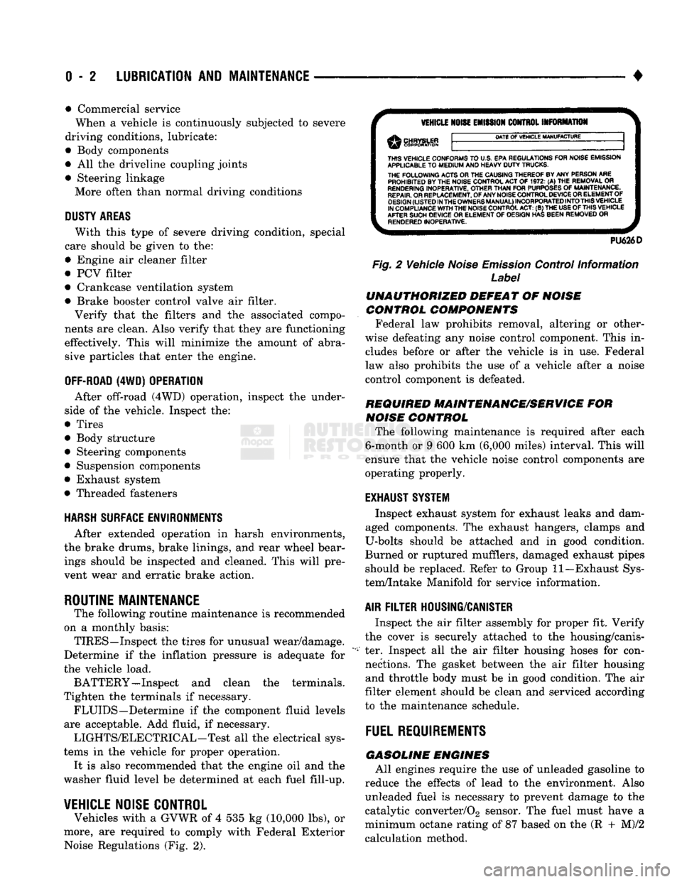
more, are required to comply with Federal Exterior Noise Regulations (Fig. 2).
VEHICLE
NOISE
EMISSION
CONTROL INFORMATION
DATE
OF
VEHICLE
MANUFACTURE
THIS
VEHICLE CONFORMS
TO
U.S. EPA REGULATIONS FOR NOISE EMISSION
APPLICABLE
TO
MEDIUM
AND HEAVY
DUTY
TRUCKS. THE
FOLLOWING
ACTS OR THE CAUSING THEREOF BY ANY PERSON ARE PROHIBITED BY THE NOISE CONTROL ACT
OF 1972. (A) THE
REMOVAL
OR
RENDERING
INOPERATIVE, OTHER
THAN
FOR
PURPOSES
OF
MAINTENANCE,
REPAIR.
OR REPLACEMENT, OF ANY NOISE CONTROL DEVICE OR ELEMENT OF
DESIGN
(LISTED
IN
THE
OWNERS
MANUAL)
INCORPORATED
INTO
THIS
VEHICLE
IN COMPLIANCE
WITH
THE NOISE CONTROL
ACT:
(B) THE
USE
OF
THIS
VEHICLE
AFTER SUCH DEVICE
OR
ELEMENT
OF
DESIGN HAS BEEN REMOVED
OR
RENDERED
INOPERATIVE.
PU626D
Fig.
2 Vehicle
Noise
Emission
Control Information
Label
UNAUTHORIZED
DEFEAT
OF
NOISE
CONTROL COMPONENTS
Federal law prohibits removal, altering or other
wise defeating any noise control component. This in
cludes before or after the vehicle is in use. Federal
law also prohibits the use of a vehicle after a noise
control component is defeated.
REQUIRED MAINTENANCE/SERVICE
FOR
NOISE
CONTROL
The following maintenance is required after each
6-month or 9 600 km (6,000 miles) interval. This will
ensure that the vehicle noise control components are
operating properly.
EXHAUST SYSTEM
Inspect exhaust system for exhaust leaks and dam
aged components. The exhaust hangers, clamps and
U-bolts should be attached and in good condition.
Burned or ruptured mufflers, damaged exhaust pipes should be replaced. Refer to Group 11—Exhaust Sys
tem/Intake Manifold for service information.
AIR
FILTER
HOUSING/CANISTER
Inspect the air filter assembly for proper fit. Verify
the cover is securely attached to the housing/canis
ter. Inspect all the air filter housing hoses for con nections. The gasket between the air filter housing and throttle body must be in good condition. The air
filter element should be clean and serviced according
to the maintenance schedule.
FUEL
REQUIREMENTS
GASOLINE
ENGINES
All engines require the use of unleaded gasoline to
reduce the effects of lead to the environment. Also unleaded fuel is necessary to prevent damage to the
catalytic converter/02 sensor. The fuel must have a
minimum octane rating of 87 based on the (R + M)/2
calculation method.
Page 33 of 1502

0 - 14
LUBRICATION
AND
MAINTENANCE
•
ENGINE
MAINTENANCE
INDEX
page
Air
Injection
Systems/Air Pump
. 17
Air-Conditioner
Compressor
21
Battery
19
Cooling System
15
Crankcase
Ventilation
System
17
Diesel Engine
Air Filter
Canister
17
Drive Belts
20
Engine
Air
Cleaner
Filter
Element
16
Engine Break-In
14
Engine
Oil 14
Engine
Oil
Change
and Filter
Replacement
15
Exhaust Gas
Recirculation
(EGR) System
...... 19
page
Exhaust
Manifold
Heat
Control
Valve
. 17
Exhaust System
, 21
Fuel System
18
Hoses
and
Fittings
16
Ignition
Cables,
Distributor
Cap and
Rotor
...... 19
Ignition
Timing
. 19
Oxygen
(02)
Sensor
19
Rubber/Plastic Components
20
Spark Plugs
. 19
Throttle
Control
Linkage
18
Vacuum Operated, Emission
Control
Components
19
ENGINE BREAK-IN
After first starting a new engine, allow it to idle
for 15 seconds before shifting into a drive gear. Also:
• Drive the vehicle at varying speeds less than 88
km/h (55 mph) for the first 480 km (300 miles).
• Avoid fast acceleration and sudden stops.
• Do not drive at full-throttle for extended periods of
time
• Do not drive at constant speeds
• Do not idle the engine excessively A special break-in engine oil is not required. The
original engine oil installed is a high quality lubri
cant. New engines tend to consume more fuel and oil un
til after the break-in period has ended.
ENGINE
OIL SPECIFICATIONS
API SERWICE
GRADE
Use an engine oil that conforms to API Service
Grade S5 SG/CD or SG/CE. MOPAR®provides engine
oils that conform to all of these service grades.
SULFATED ASH—DIESEL ENGINES
Oils that contain an excessive amount of sulfated
ash can cause deposits to develop on Diesel engine
valves. These deposits can result in valve wear.
SAE
WISC0SITY
An SAE viscosity grade is used to specify the vis
cosity of engine oil. SAE 30 specifies a single viscos
ity engine oil.
Engine oils also have multiple viscosities. 10W-30
<
5W-30
1
1 1
F
-20 0 10 20 32 60 80 100
C
-29 -18 -12 -7 0 16 27 38
ANTICIPATED
TEMPERATURE RANGE BEFORE
NEXT
OIL
CHANGE
J9000-39
Fig.
1 Temperature/Engine Oil Viscosity—Gasoline
Engines
-12°C
-18°C 10°F
0°F- 15W-40
-23°c(^-10eF
I
10W-30
WITH
WITHOUT
BLOCK HEATER
BLOCK
SYNTHETIC
OIL
HEATER
10W-30 5W-30
J9100-29
Fig.
2 Temperature/Engine Oil Viscosity—Diesel
Engines
ENERGY
G0NSERWING
OIL
An Energy Conserving type oil is recommended for
gasoline engines. They are designated as either EN
ERGY CONSERVING or ENERGY CONSERVING
II.
OIL
LEVEL
INDICATOR (DIPSTICK)
GASOLINE ENGINES
The engine oil indicator is located at the right
front of the engine.
Page 250 of 1502
•
BRAKES
5 - 63 You must count the long flash along with the
short flashes for an accurate fault code count.
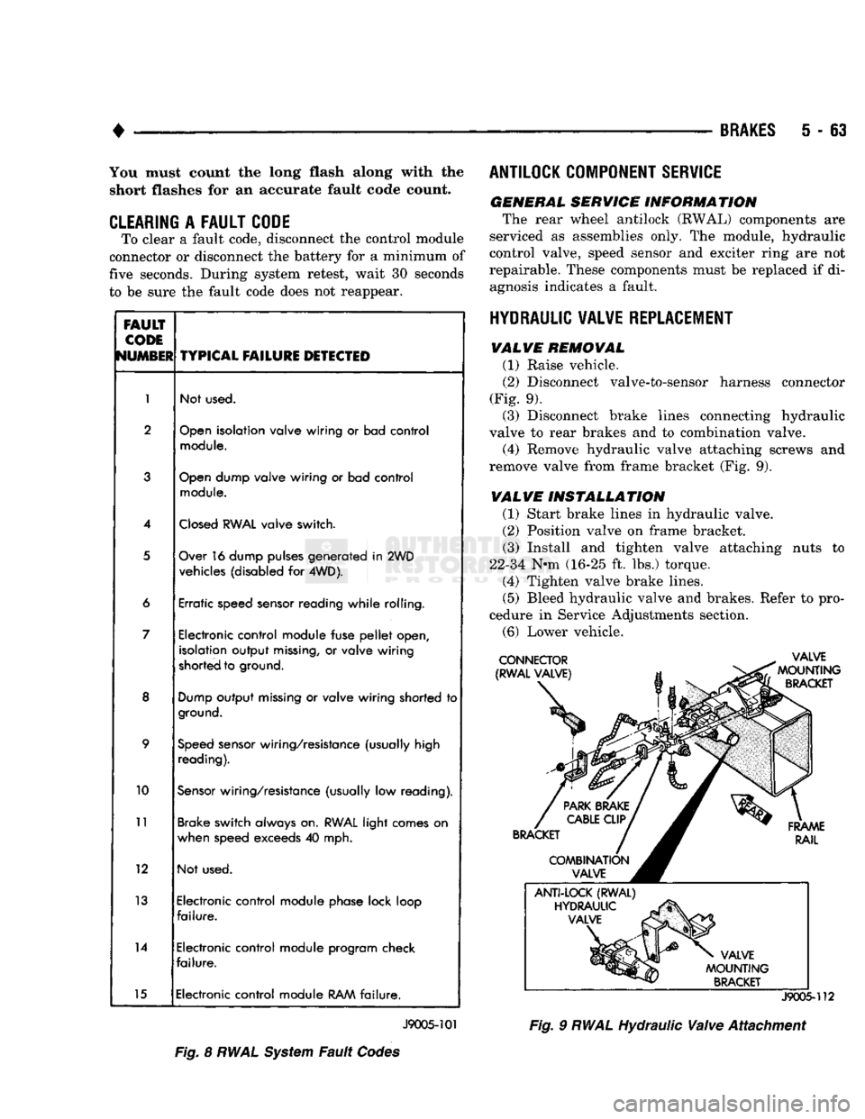
CLEARING
A
FAULT CODE
To clear a fault code, disconnect the control module
connector or disconnect the battery for a minimum of
five seconds. During system retest, wait 30 seconds
to be sure the fault code does not reappear.
FAULT
CODE
NUMBER
TYPICAL
FAILURE
DETECTED
1
Not used.
2
Open
isolation valve wiring
or
bad control
module.
3
Open
dump valve wiring
or
bad control
module.
4
Closed
RWAL
valve switch.
5
Over 16 dump pulses generated
in
2WD
vehicles (disabled
for
4WD).
6 Erratic speed sensor reading while rolling.
7 Electronic control module fuse
pellet
open,
isolation output
missing,
or
valve wiring
shorted to ground.
8
Dump
output
missing
or
valve wiring shorted
to
ground.
9
Speed
sensor wiring/resistance (usually high
reading).
10
Sensor
wiring/resistance (usually
low
reading).
11
Brake switch always on.
RWAL
light comes
on
when speed exceeds
40
mph.
12 Not used.
13 Electronic control module phase lock loop
failure.
14 Electronic control module program check
failure.
15 Electronic control module
RAM
failure.
J9005-101
Fig.
8
RWAL
System
Fault
Codes ANTILOCK COMPONENT SERVICE
GENERAL SERVICE INFORMATION
The rear wheel antilock (RWAL) components are
serviced as assemblies only. The module, hydraulic
control valve, speed sensor and exciter ring are not
repairable. These components must be replaced if di agnosis indicates a fault.
HYDRAULIC VALVE REPLACEMENT VALVE REMOVAL
(1) Raise vehicle.
(2)
Disconnect valve-to-sensor harness connector
(Fig. 9). (3) Disconnect brake lines connecting hydraulic
valve to rear brakes and to combination valve.
(4) Remove hydraulic valve attaching screws and
remove valve from frame bracket (Fig. 9).
VALVE INSTALLATION
(1) Start brake lines in hydraulic valve.
(2)
Position valve on frame bracket. (3) Install and tighten valve attaching nuts to
22-34 N-m (16-25 ft. lbs.) torque. (4) Tighten valve brake lines.
(5)
Bleed hydraulic valve and brakes. Refer to pro
cedure in Service Adjustments section.
(6)
Lower vehicle.
J9005-112
Fig.
9
RWAL
Hydraulic
Valve
Attachment
Page 295 of 1502
7 - 24
COOLING SYSTEM
• If the thermostat is being replaced, be sure that
the replacement is the specified thermostat for the vehicle model and engine type. Factory installed thermostat housings on 3.9L/5.2L/
5.9L engines are installed on a gasket with an anti-
stick coating. This will aid in gasket removal and
clean-up.
(1) Disconnect negative battery cable at battery.
(2) Drain cooling system until coolant level is be
low thermostat. Refer to Draining Cooling System in
this group. If not equipped with air conditioning, pro ceed to step number 4.
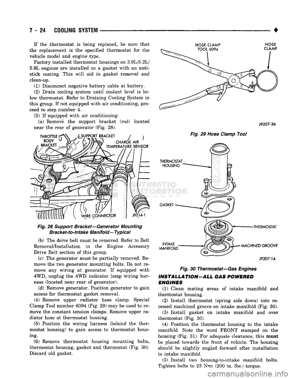
(3) If equipped with air conditioning: (a) Remove the support bracket (rod) located
near the rear of generator (Fig. 28).
Fig.
28
Support
Bracket—Generator
Mounting
Bracket-to-intake
Manifold—
Typical
(b) The drive belt must be removed. Refer to Belt
Removal/Installation in the Engine Accessory
Drive Belt section of this group.
(c) The generator must be partially removed. Re
move the two generator mounting bolts. Do not re
move any wiring at generator. If equipped with
4WD,
unplug the 4WD indicator lamp wiring har
ness (located near rear of generator).
(d) Remove generator. Position generator to gain
access for thermostat gasket removal.
(4) Remove upper radiator hose clamp. Special
Clamp Tool number 6094 (Fig. 29) may be used to re
move the constant tension clamps. Remove upper ra
diator hose at thermostat housing.
(5) Position the wiring harness (behind the ther
mostat housing) to gain access to thermostat hous ing.
(6) Remove thermostat housing mounting bolts,
thermostat housing, gasket and thermostat (Fig. 30). Discard old gasket.
HOSE CLAMP HOSE
J9207-36
Fig.
29
Hose
Clamp
Tool
•THERMOSTAT
MACHINED GROOVE
J9207-14
Fig.
30 Thermostat—Gas
Engines
INSTALLATION-ALL GAS
POWERED
ENGINES
(1) Clean mating areas of intake manifold and
thermostat housing. (2) Install thermostat (spring side down) into re
cessed machined groove on intake manifold (Fig. 30).
(3) Install gasket on intake manifold and over
thermostat (Fig. 30).
(4) Position the thermostat housing to the intake
manifold. Note the word FRONT stamped on the
housing (Fig. 31). For adequate clearance, this must
be placed towards the front of vehicle. The housing should be slightly angled forward after installation
to intake manifold.
(5) Install two housing-to-intake manifold bolts.
Tighten bolts to 23 N-m (200 in. lbs.) torque.
Page 306 of 1502
•
COOLING
SYSTEM
7 - 35
HOSE
CLAMP TOOL
6094
HOSE
CLAMP
J9207-36
Fig.
48
Hose
damp Tool
TRANSMISSION
OIL
COOLER—EXCEPT DIESEL
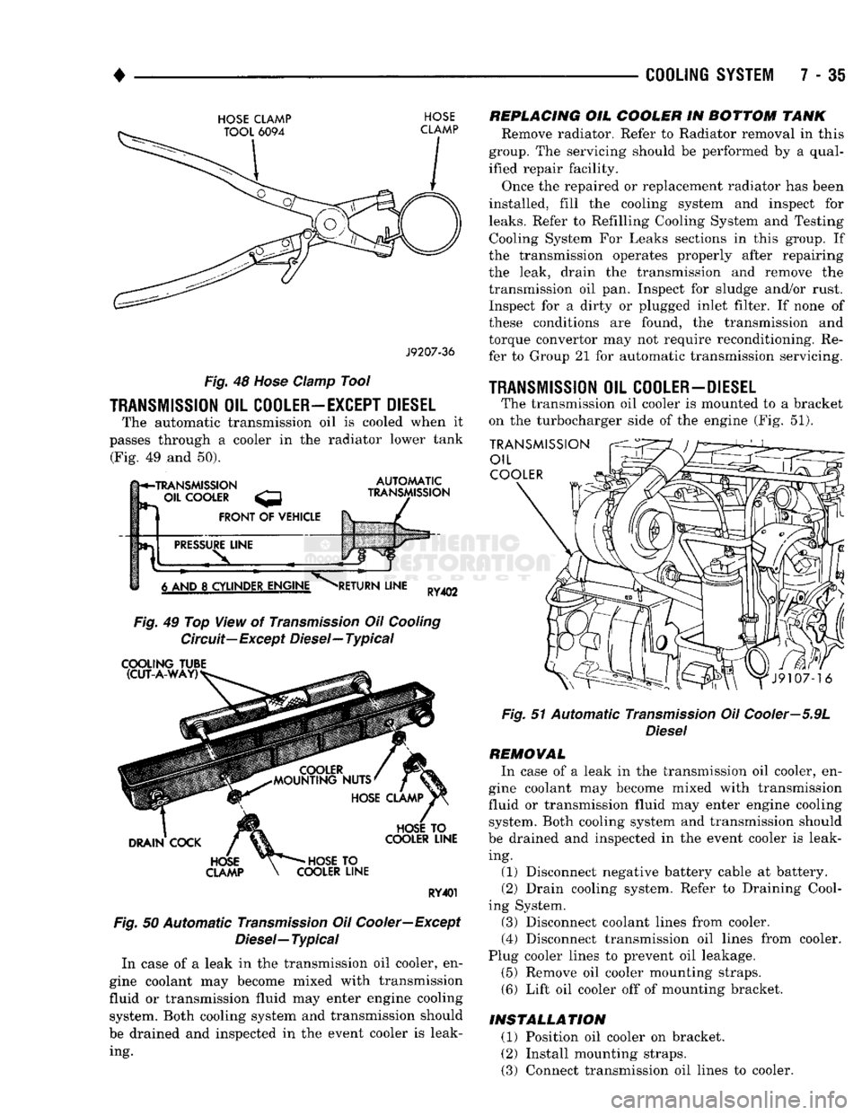
The automatic transmission oil is cooled when it
passes through a cooler in the radiator lower tank (Fig. 49 and 50).
h*-TRANSMISSION
- OIL
COOLER
FRONT
OF
VEHICLE
AUTOMATIC
TRANSMISSION
PRESSURE
LINE
6 AND
8
CYLINDER ENGINE
RETURN
LINE
RY402
Fig.
49 Top View of
Transmission
Oil
Cooling
Circuit—Except Diesel—Typical
COOLING
TUBE (CUT-A-WAY)
DRAIN
COCK
HOSE
CLAMP
HOSE
TO
COOLER
LINE
HOSE
TO
COOLER
LINE
RY401
Fig.
50 Automatic
Transmission
Oil Cooler—Except
Diesel—
Typical
In case of a leak in the transmission oil cooler, en
gine coolant may become mixed with transmission
fluid or transmission fluid may enter engine cooling system. Both cooling system and transmission should
be drained and inspected in the event cooler is leak ing.
REPLACING
OIL
COOLER
IN
BOTTOM
TANK
Remove radiator. Refer to Radiator removal in this
group. The servicing should be performed by a qual
ified repair facility.
Once the repaired or replacement radiator has been
installed, fill the cooling system and inspect for
leaks.
Refer to Refilling Cooling System and Testing Cooling System For Leaks sections in this group. If
the transmission operates properly after repairing
the leak, drain the transmission and remove the
transmission oil pan. Inspect for sludge and/or rust. Inspect for a dirty or plugged inlet filter. If none of
these conditions are found, the transmission and
torque convertor may not require reconditioning. Re
fer to Group 21 for automatic transmission servicing.
1RANSMISSI0N
OIL
COOLER-DIESEL
The transmission oil cooler is mounted to a bracket
on the turbocharger side of the engine (Fig. 51).
TRANSMISSION
OIL
COOLER
Fig.
51 Automatic
Transmission
Oil Cooler—5.9L
Diesel
REMOVAL
In case of a leak in the transmission oil cooler, en
gine coolant may become mixed with transmission
fluid or transmission fluid may enter engine cooling system. Both cooling system and transmission should
be drained and inspected in the event cooler is leak ing. (1) Disconnect negative battery cable at battery.
(2) Drain cooling system. Refer to Draining Cool
ing System. (3) Disconnect coolant lines from cooler.
(4) Disconnect transmission oil lines from cooler.
Plug cooler lines to prevent oil leakage. (5) Remove oil cooler mounting straps.
(6) Lift oil cooler off of mounting bracket.
INSTALLATION
(1) Position oil cooler on bracket.
(2) Install mounting straps.
(3) Connect transmission oil lines to cooler.
Page 333 of 1502
8A
- 12
ELECTRICAL
•
ENGINE
STARTER
RELAY
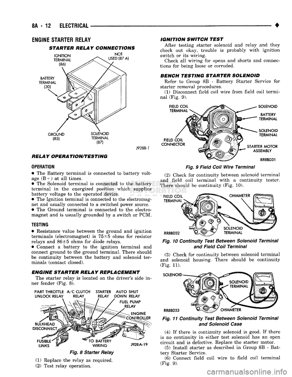
STARTER RELAY CONNECTIONS
GROUND SOLENOID (85) TERMINAL
(87) J928B-1
RELAY OPERATION/TESTING
OPERATION
• The Battery terminal is connected to battery volt
age (B +
)
at all times.
• The Solenoid terminal is connected to the battery
terminal in the energized position which supplies
battery voltage to the operated device. • The Ignition terminal is connected to the electromag
net and usually connected to a switched power source.
• The Ground terminal is connected to the electro
magnet and is usually grounded by a switch or PCM.
TESTING
• Resistance value between the ground and ignition
terminals (electromagnet) is
75
±5 ohms for resistor
relays and 86±5 ohms for diode relays.
• Connect a battery to the ignition terminal and
connect ground to the ground terminal. There should
be continuity between the battery and solenoid ter minals (contact closed).
ENGINE STARTER RELAY REPLACEMENT The starter relay is located on the driver's side in
ner fender (Fig. 8).
PART THROTTLE
A/C
CLUTCH STARTER AUTO SHUT
UNLOCK RELAY RELAY RELAY DOWN RELAY
Fig.
8
Starter
Relay
(1) Replace the relay as required.
(2) Test relay operation. IGNITION SWITCH TEST
After testing starter solenoid and relay and they
check out okay, trouble is probably with ignition
switch or its wiring. Check all wiring for opens and shorts and connec
tions for being loose or corroded.
BENCH TESTING STARTER SOLENOID Refer to Group 8B - Battery Starter Service for
starter removal procedures. (1) Disconnect field coil wire from field coil termi
nal (Fig. 9).
Fig.
9 Field
Coil
Wire
Terminal
(2) Check for continuity between solenoid terminal
and field coil terminal with a continuity tester.
There should be continuity (Fig. 10).
Fig.
10 Continuity Test Between
Solenoid
Terminal
and
Field
Coil
Terminal
(3) Check for continuity between solenoid terminal
and solenoid housing. There should be continuity
(Fig. 11).
SOLENOID
RR8BD33 Fig.
11 Continuity Test Between
Solenoid
Terminal
and Solenoid Case
(4) If there is continuity solenoid is good. If there
is no continuity in either test solenoid has an open
circuit and is defective. Replace the starter motor. (5) Install starter as described in Group 8B - Bat
tery Starter Service. (6) Connect field coil wire to field coil terminal
(Fig. 9).
Page 342 of 1502
• BATTERY/STARTER/GENERATOR
SERVICE
8B - 1
CONTENTS
page page
BATTERY
SERVICE
PROCEDURES
1 SPECIFICATIONS 9
GENERATOR
SERVICE
6 STARTER
SERVICE
PROCEDURES
4
BATTERY SERVICE PROCEDURES
GENERAL
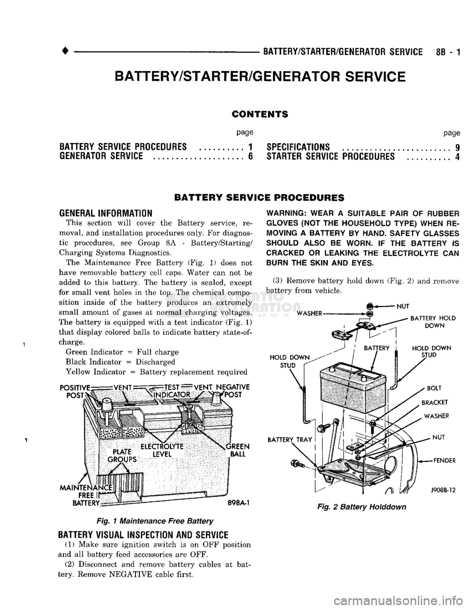
INFORMATION This section will cover the Battery service, re
moval, and installation procedures only. For diagnos
tic procedures, see Group 8A - Battery/Starting/ Charging Systems Diagnostics. The Maintenance Free Battery (Fig. 1) does not
have removable battery cell caps. Water can not be added to this battery. The battery is sealed, except
for small vent holes in the top. The chemical compo sition inside of the battery produces an extremely
small amount of gases at normal charging voltages.
The battery is equipped with a test indicator (Fig. 1)
that display colored balls to indicate battery
state-of-
charge. Green Indicator = Full charge
Black Indicator = Discharged
Yellow Indicator = Battery replacement required Fig. 1 Maintenance Free Battery
BATTERY
VISUAL INSPECTION AND
SERVICE
(1) Make sure ignition switch is on OFF position
and all battery feed accessories are OFF. (2) Disconnect and remove battery cables at bat
tery. Remove NEGATIVE cable first.
WARNING: WEAR
A
SUITABLE PAIR
OF
RUBBER
GLOVES
(NOT THE
HOUSEHOLD TYPE) WHEN
RE
MOVING
A
BATTERY
BY
HAND. SAFETY
GLASSES
SHOULD ALSO
BE
WORN.
IF THE
BATTERY
IS
CRACKED
OR
LEAKING
THE
ELECTROLYTE
CAN
BURN
THE
SKIN
AND
EYES.
(3) Remove battery hold down (Fig. 2) and remove
battery from vehicle. Fig. 2 Battery
Holddown
BATTERY/STARTER/GENERATOR
SERVICE
Page 347 of 1502
8B
- 6
BATTERY/STARTER/GENERATOR
SERVICE
•
GENERATOR SERVICE
CONTENTS
page
GENERATOR
REPLACEMENT-
DIESEL
ENGINE
8
GENERAL
INFORMATION
6
GENERAL
INFORMATION This section will cover generator removal
and in
stallation.
The
generator
is not
serviceable. Informa
tion covering on-vehicle testing
can be
found
in
Group
8A -
Battery/Starting/Charging/System Diag
nostics. The standard equipment generator
on the D and W
bodies
is the 75 amp
generator.
The
Ramcharger
is
equipped with
the 90 amp
generator. When
a
vehicle
is equipped with
a
heavy duty package
or
diesel
en
gine,
a 120 amp
generator
is
used.
GENERATOR
REPLACEMENT
-3.9L/5.2L/5.9L-LDC
GAS
ENGINE
Drive belts
on
these engines
are
equipped with
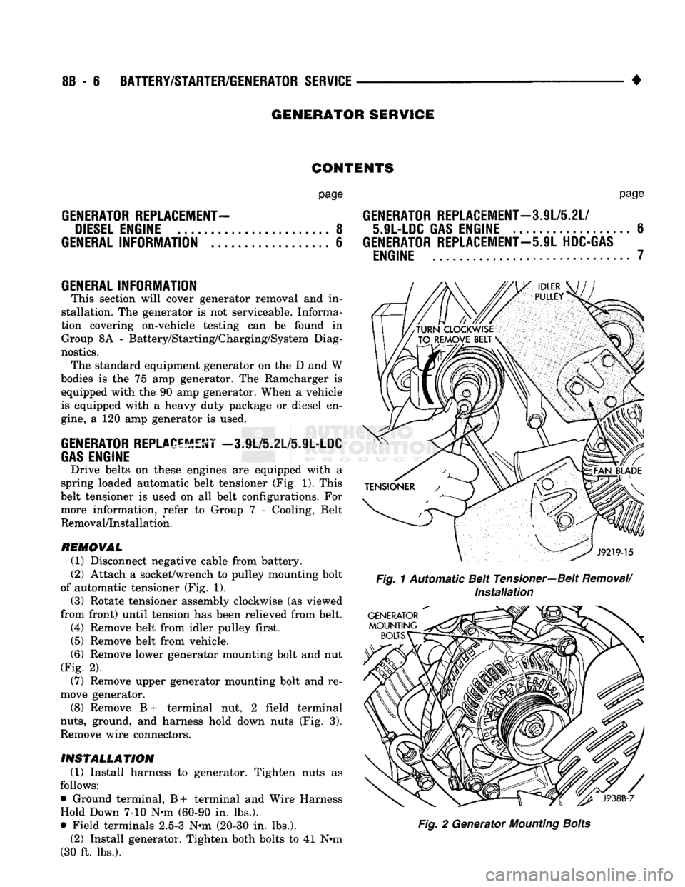
a
spring loaded automatic belt tensioner
(Fig. 1).
This
belt tensioner
is
used
on all
belt configurations.
For
more information, refer
to
Group
7 -
Cooling, Belt
Removal/Installation.
REMOVAL
(1) Disconnect negative cable from battery.
(2) Attach
a
socket/wrench
to
pulley mounting bolt
of automatic tensioner
(Fig. 1).
(3) Rotate tensioner assembly clockwise
(as
viewed
from front) until tension
has
been relieved from belt. (4) Remove belt from idler pulley first.
(5) Remove belt from vehicle.
(6)
Remove lower generator mounting bolt
and nut
(Fig.
2).
(7) Remove upper generator mounting bolt
and re
move generator.
(8) Remove
B+
terminal
nut, 2
field terminal
nuts,
ground,
and
harness hold down nuts
(Fig. 3).
Remove wire connectors.
INSTALLATION
(1) Install harness
to
generator. Tighten nuts
as
follows:
• Ground terminal,
B+
terminal
and
Wire Harness Hold Down
7-10 N*m
(60-90
in.
lbs.).
• Field terminals
2.5-3 N-m
(20-30
in.
lbs.). (2) Install generator. Tighten both bolts
to 41 N»m
(30
ft.
lbs.).
page
GENERATOR
REPLACEMENT—3.9L/5.2L/
5.9L-LDC
GAS
ENGINE
6
GENERATOR
REPLACEMENT—5.9L
HDC-GAS
ENGINE
7
Fig.
1 Automatic Belt Tensioner—Belt
Removal/
Installation
Fig.
2
Generator
Mounting
Bolts