1993 DODGE TRUCK bolt pattern
[x] Cancel search: bolt patternPage 89 of 1502
2
- 36
FRONT
SUSPENSION
AND
AXLE
• • Pinion gear mate shaft (align holes in shaft and
case) (2) Install and seat the lock pin in the differential
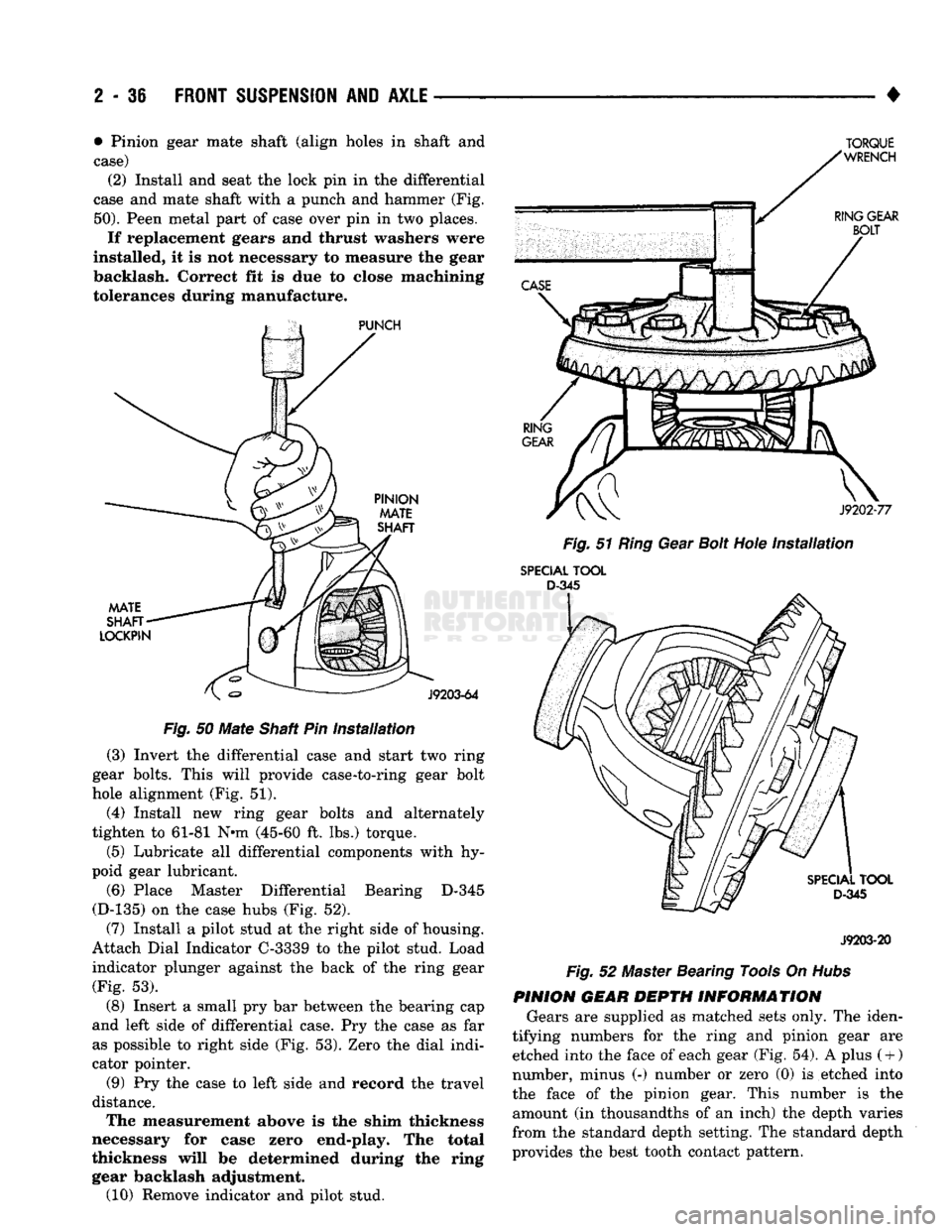
case and mate shaft with a punch and hammer (Fig.
50).
Peen metal part of case over pin in two places.
If replacement gears and thrust washers were
installed, it is not necessary to measure the gear
backlash. Correct fit is due to close machining
tolerances during manufacture.
Fig.
50
Mate
Shaft Pin
installation
(3) Invert the differential case and start two ring
gear bolts. This will provide case-to-ring gear bolt
hole alignment (Fig. 51).
(4) Install new ring gear bolts and alternately
tighten to 61-81 N*m (45-60 ft. lbs.) torque.
(5) Lubricate all differential components with hy
poid gear lubricant.
(6) Place Master Differential Bearing D-345
(D-135) on the case hubs (Fig. 52).
(7) Install a pilot stud at the right side of housing.
Attach Dial Indicator C-3339 to the pilot stud. Load
indicator plunger against the back of the ring gear (Fig. 53).
(8) Insert a small pry bar between the bearing cap
and left side of differential case. Pry the case as far as possible to right side (Fig. 53). Zero the dial indi
cator pointer.
(9) Pry the case to left side and record the travel
distance. The measurement above is the shim thickness
necessary for case zero end-play. The total
thickness will be determined during the ring gear backlash adjustment. (10) Remove indicator and pilot stud.
TORQUE
Fig.
51
Ring
Gear
Bolt
Hole
Installation
SPECIAL
TOOL
D-345
J9203-20
Fig.
52 Master Bearing Tools On
Hubs
PINION GEAR DEPTH INFORMATION Gears are supplied as matched sets only. The iden
tifying numbers for the ring and pinion gear are etched into the face of each gear (Fig. 54). A plus
(
+ )
number, minus (-) number or zero (0) is etched into
the face of the pinion gear. This number is the amount (in thousandths of an inch) the depth varies
from the standard depth setting. The standard depth
provides the best tooth contact pattern.
Page 98 of 1502
4
____________
(10) Install bearing
on hub
with Installer
D-156
and Handle C-4171
(Fig. 82).
(11) Install
new
axle shaft
oil
seal
in
differential
housing with Installer D-112-44. Apply lubricant
to
lip
of
seal. (12) Match each bearing
cup
with bearing (origi
nal).
Install
the
cups
on the
bearings.
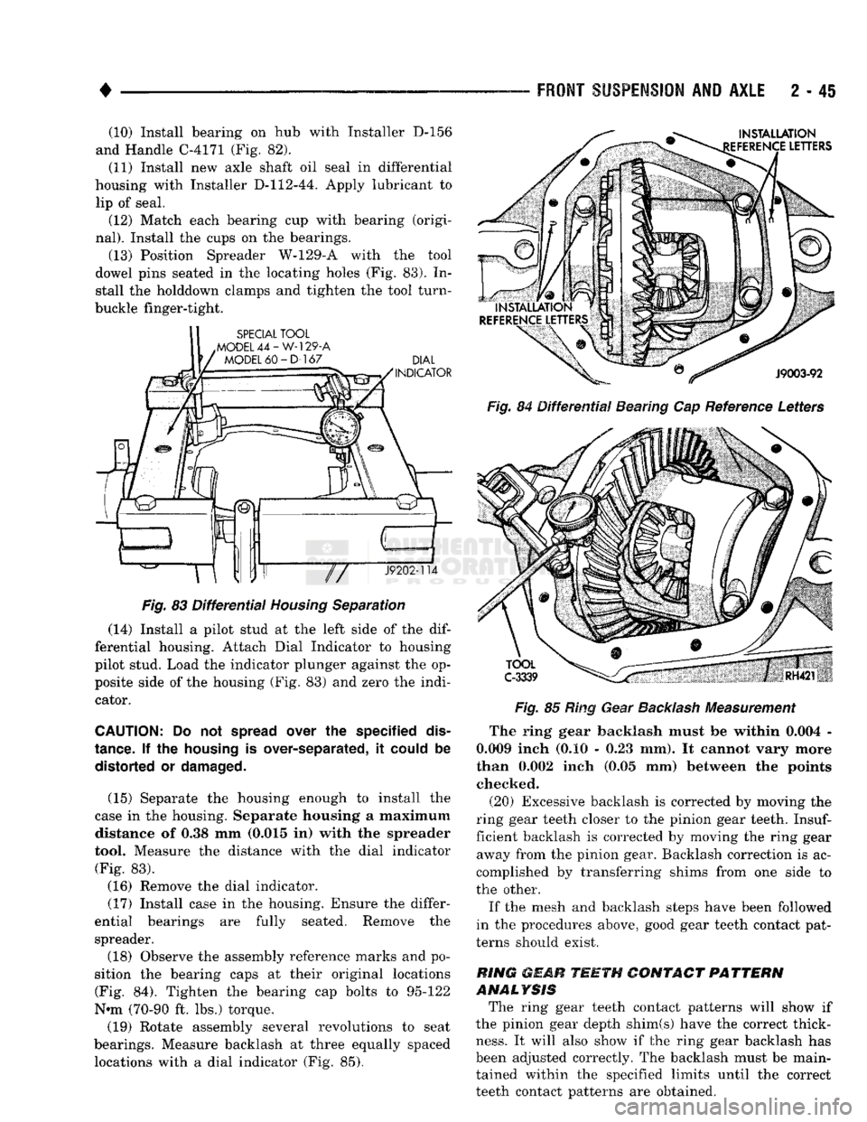
(13) Position Spreader W-129-A with
the
tool
dowel pins seated
in the
locating holes
(Fig. 83). In
stall
the
holddown clamps
and
tighten
the
tool turn-
buckle finger-tight.
Fig.
83
Differential
Housing
Separation
(14) Install
a
pilot stud
at the
left side
of the dif
ferential housing. Attach Dial Indicator
to
housing
pilot stud. Load
the
indicator plunger against
the op
posite side
of the
housing
(Fig. 83) and
zero
the
indi cator.
CAUTION:
Do not
spread
over
the
specified
dis
tance.
If the
housing
is
over-separated,
it
could
be
distorted
or
damaged.
(15) Separate
the
housing enough
to
install
the
case
in the
housing. Separate housing
a
maximum distance
of 0.38 mm
(0.015
in)
with
the
spreader
tool. Measure
the
distance with
the
dial indicator (Fig.
83).
(16) Remove
the
dial indicator.
(17) Install case
in the
housing. Ensure
the
differ
ential bearings
are
fully seated. Remove
the
spreader.
(18) Observe
the
assembly reference marks
and po
sition
the
bearing caps
at
their original locations (Fig.
84).
Tighten
the
bearing
cap
bolts
to
95-122
N-m (70-90
ft. lbs.)
torque.
(19) Rotate assembly several revolutions
to
seat
bearings. Measure backlash
at
three equally spaced locations with
a
dial indicator
(Fig. 85).
FRONT
SUSPENSION
AND
AXLE
2 - 45
Fig.
84
Differential
Bearing
Cap
Reference Letters
Fig.
85
Ring Gear
Backlash
Measurement
The ring gear backlash must
be
within 0.004
-
0.009 inch
(0.10 - 0.23 mm). It
cannot vary more
than 0.002 inch
(0.05 mm)
between
the
points checked.
(20) Excessive backlash
is
corrected
by
moving
the
ring gear teeth closer
to the
pinion gear teeth.
Insuf
ficient backlash
is
corrected
by
moving
the
ring gear away from
the
pinion gear. Backlash correction
is ac
complished
by
transferring shims from
one
side
to
the other.
If
the
mesh
and
backlash steps have been followed
in
the
procedures above, good gear teeth contact pat
terns should exist.
RING
mMR
TEETH
CONTACT
PATTERN
ANALYSIS The ring gear teeth contact patterns will show
if
the pinion gear depth shim(s) have
the
correct thick
ness.
It
will also show
if the
ring gear backlash
has
been adjusted correctly.
The
backlash must
be
main tained within
the
specified limits until
the
correct
teeth contact patterns
are
obtained.
Page 117 of 1502
2
- 64
FRONT
SUSPENSION
AND
AXLE
—
Fig.
47 Ring Gear Bolt Hole
installation
MASTER BEARING
RY652
Fig.
48 Master Bearing Tools On
Hubs
The measurement above is the shim thickness
necessary for case zero end-play. The total
thickness will be determined during the ring gear backlash adjustment. (10) Remove indicator and pilot stud.
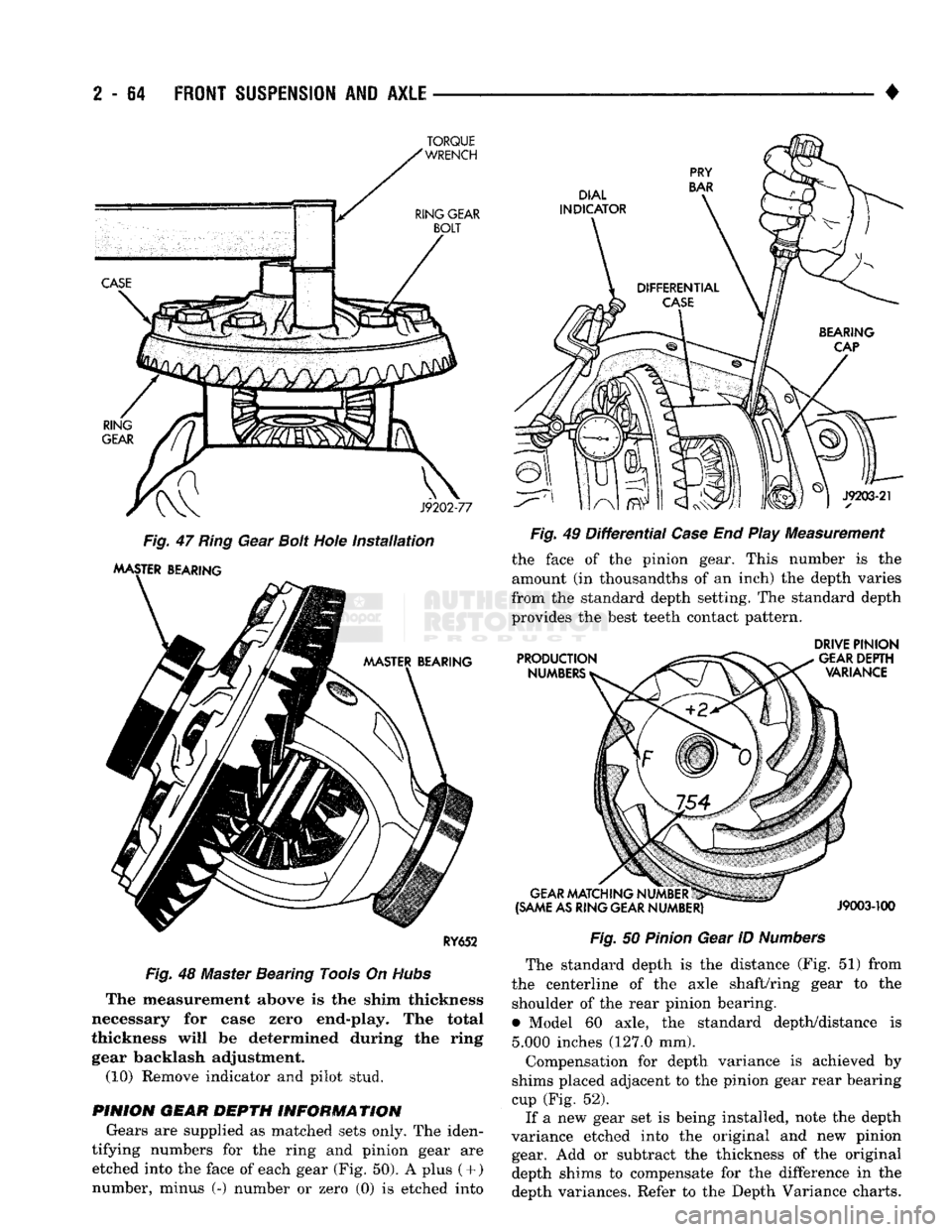
PINION GEAR DEPTH INFORMATION Gears are supplied as matched sets only. The iden
tifying numbers for the ring and pinion gear are etched into the face of each gear (Fig. 50). A plus
(
+ )
number, minus (-) number or zero (0) is etched into •
Fig.
49
Differential
Case
End Play Measurement the face of the pinion gear. This number is the
amount (in thousandths of an inch) the depth varies
from the standard depth setting. The standard depth
provides the best teeth contact pattern.
DRIVE
PINION
Fig.
50
Pinion
Gear ID
Numbers
The standard depth is the distance (Fig. 51) from
the centerline of the axle shaft/ring gear to the shoulder of the rear pinion bearing.
• Model 60 axle, the standard depth/distance is
5.000
inches (127.0 mm).
Compensation for depth variance is achieved by
shims placed adjacent to the pinion gear rear bearing
cup (Fig. 52). If a new gear set is being installed, note the depth
variance etched into the original and new pinion gear. Add or subtract the thickness of the original
depth shims to compensate for the difference in the
depth variances. Refer to the Depth Variance charts.
TORQUE
Page 126 of 1502
•
FRONT
SUSPENSION
AND
AXLE
2 - 73
SPECIAL TOOL
.MODEL
44-W-129-A
MODEL
60 - D-167
DIAL
INDICATOR
J9202-114
TOOL
C-3339
Fig.
80
Differential
Housing
Separation
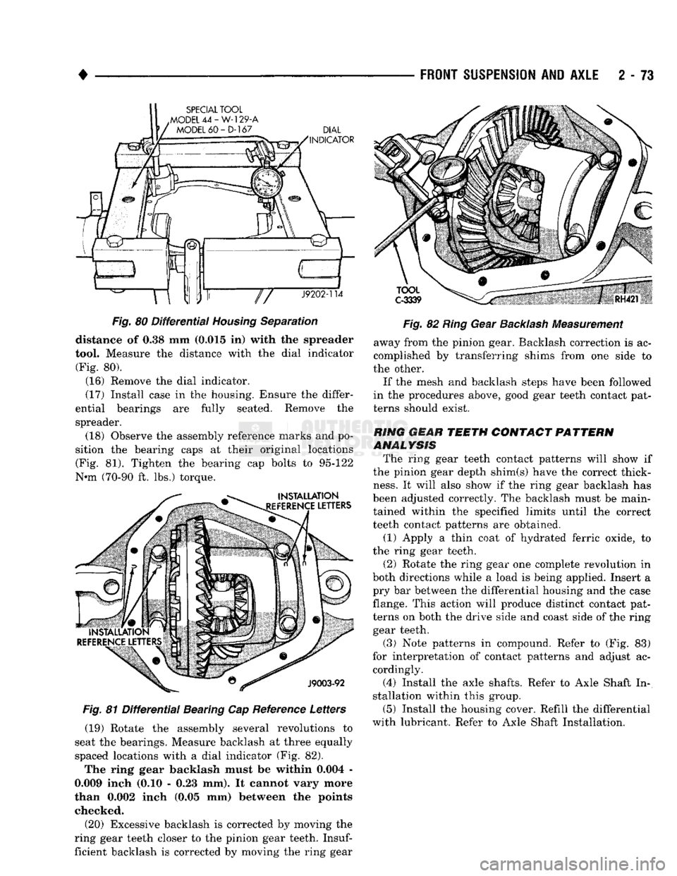
distance
of 0.38 mm
(0.015
in)
with
the
spreader
tool. Measure
the
distance with
the
dial indicator
(Fig.
80).
(16) Remove
the
dial indicator.
(17) Install case
in the
housing. Ensure
the
differ
ential bearings
are
fully seated. Remove
the
spreader.
(18) Observe
the
assembly reference marks
and po
sition
the
bearing caps
at
their original locations (Fig.
81).
Tighten
the
bearing
cap
bolts
to
95-122
Nnn (70-90
ft. lbs.)
torque.
Fig.
81
Differential
Bearing
Cap
Reference Letters (19) Rotate
the
assembly several revolutions
to
seat
the
bearings. Measure backlash
at
three equally
spaced locations with
a
dial indicator
(Fig. 82).
The ring gear backlash must
be
within 0.004
-
0.009 inch
(0.10 - 0.23 mm). It
cannot vary more
than 0.002 inch
(0.05 mm)
between
the
points checked.
(20) Excessive backlash
is
corrected
by
moving
the
ring gear teeth closer
to the
pinion gear teeth.
Insuf
ficient backlash
is
corrected
by
moving
the
ring gear
Fig.
82
Ring
Gear
Backlash
Measurement
away from
the
pinion gear. Backlash correction
is ac
complished
by
transferring shims from
one
side
to
the other.
If
the
mesh
and
backlash steps have been followed
in
the
procedures above, good gear teeth contact pat
terns should exist.
RING GEAR TEETH CONTACT PATTERN
ANALYSIS
The ring gear teeth contact patterns will show
if
the pinion gear depth shim(s) have
the
correct thick
ness.
It
will also show
if the
ring gear backlash
has
been adjusted correctly.
The
backlash must
be
main
tained within
the
specified limits until
the
correct
teeth contact patterns
are
obtained.
(1) Apply
a
thin coat
of
hydrated ferric oxide,
to
the ring gear teeth. (2) Rotate
the
ring gear
one
complete revolution
in
both directions while
a
load
is
being applied. Insert
a
pry
bar
between
the
differential housing
and the
case
flange. This action will produce distinct contact pat terns
on
both
the
drive side
and
coast side
of the
ring gear teeth.
(3) Note patterns
in
compound. Refer
to (Fig. 83)
for interpretation
of
contact patterns
and
adjust
ac
cordingly.
(4) Install
the
axle shafts. Refer
to
Axle Shaft
In
stallation within this group.
(5) Install
the
housing cover. Refill
the
differential
with lubricant. Refer
to
Axle Shaft Installation.
Page 139 of 1502
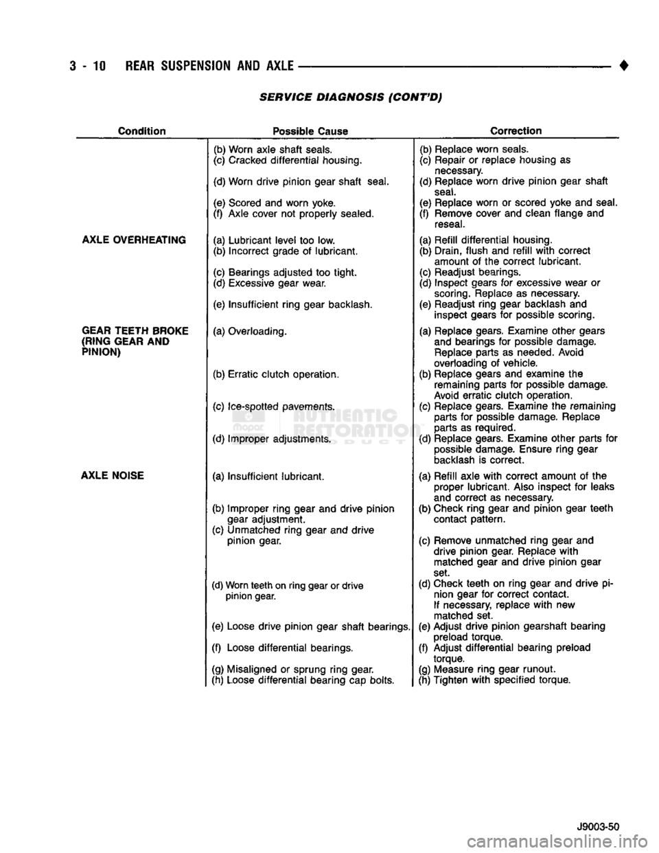
3-10
REAR SUSPENSION
AND
AXLE
SERVICE DIAGNOSIS (CONT'D)
Condition
Possible
Cause
Correction
AXLE OVERHEATING
GEAR TEETH BROKE
(RING GEAR
AND
PINION)
AXLE NOISE
(b) Worn axle
shaft
seals.
(c) Cracked
differential
housing.
(d) Worn
drive
pinion
gear
shaft
seal.
(e) Scored and worn yoke.
(f) Axle cover not
properly
sealed.
(a)
Lubricant
level
too low. (b)
Incorrect
grade of
lubricant.
(c) Bearings
adjusted
too
tight.
(d) Excessive gear wear.
(e)
Insufficient
ring
gear backlash,
(a) Overloading.
(b)
Erratic
clutch
operation.
(c) Ice-spotted pavements.
(d) Improper adjustments.
(a)
Insufficient
lubricant.
(b) Improper
ring
gear and
drive
pinion
gear
adjustment.
(c) Unmatched
ring
gear and
drive
pinion
gear.
(d) Worn
teeth
on
ring
gear or
drive
pinion
gear.
(e) Loose
drive
pinion
gear
shaft
bearings.
(f) Loose
differential
bearings.
(g) Misaligned or sprung
ring
gear.
(h) Loose
differential
bearing cap bolts. (b) Replace worn
seals.
(c) Repair or replace housing as
necessary.
(d) Replace worn
drive
pinion
gear
shaft
seal.
(e) Replace worn or scored yoke and seal.
(f) Remove cover and clean flange and reseal.
(a)
Refill
differential
housing. (b) Drain,
flush
and
refill
with
correct
amount of the
correct
lubricant.
(c) Readjust bearings.
(d) Inspect gears for excessive wear or scoring. Replace as necessary.
(e) Readjust
ring
gear backlash and inspect gears for possible scoring.
(a) Replace gears. Examine
other
gears and bearings for possible damage. Replace parts as needed. Avoid
overloading of vehicle.
(b) Replace gears and examine the remaining parts for possible damage.
Avoid
erratic
clutch
operation.
(c) Replace gears. Examine the remaining parts for possible damage. Replace
parts as required.
(d) Replace gears. Examine
other
parts for possible damage. Ensure
ring
gear
backlash is
correct.
(a)
Refill
axle
with
correct
amount of the proper
lubricant.
Also inspect for leaks
and
correct
as necessary.
(b) Check
ring
gear and
pinion
gear
teeth
contact
pattern.
(c) Remove unmatched
ring
gear and
drive
pinion
gear. Replace
with
matched gear and
drive
pinion
gear
set.
(d) Check
teeth
on
ring
gear and
drive
pi nion gear for
correct
contact.
If necessary, replace
with
new
matched set.
(e) Adjust
drive
pinion
gearshaft bearing preload
torque.
(f) Adjust
differential
bearing preload
torque.
(g) Measure
ring
gear
runout.
(h) Tighten
with
specified
torque.
J9003-50
Page 175 of 1502

3
- 48
REAR
SUSPENSION
AND
AXLE
•
SPECIAL
TOOL
.MODEL
44-W-129-A
MODEL
60-D-167 (18) Rotate the assembly several revolutions to
seat bearings. Measure backlash at three equally
spaced locations with a dial indicator (Fig. 58).
Fig.
56
Differential
Housing
Separation pilot stud. Load the indicator plunger against the op
posite side of the housing (Fig. 56) and zero the indi
cator.
CAUTION:
Do not
spread
over the specified
dis
tance.
If the
housing
is over-separated, it
could
be distorted or
damaged.
(14) Separate the housing enough to install the
case in the housing. Separate housing a maximum distance of 0.38 mm (0.015 in) with the spreader
tool. Measure the distance with the dial indicator.
(15) Remove the dial indicator.
(16) Install case in the housing. Ensure the differ
ential bearings are fully seated. Remove the spreader.
(17) Observe the assembly reference marks and po
sition the bearing caps at their original locations
(Fig. 57). Tighten the bearing cap bolts to 95-122
N*m (70-90 ft. lbs.) torque.
INSTALLATION
EFERENCE
LETTERS
TOOL
C-3339
8903-31
©
^
J9003-92
Fig.
57
Differential
Bearing Cap Reference Letters
Fig.
58
Ring
Gear
Backlash
Measurement
The ring gear backlash must be within 0.004 -
0.009 inch (0.10 - 0.23 mm). It cannot vary more
than 0.002 inch (0.05 mm) between the points checked. (19) Excessive backlash is corrected by moving the
ring gear teeth closer to the pinion gear teeth.
Insuf
ficient backlash is corrected by moving the ring gear away from the pinion gear. Backlash correction is ac
complished by transferring shims from one side to
the other.
If the mesh and backlash steps have been followed
in the procedures above, good gear teeth contact pat
terns should exist.
RING
GEAR
TEETH
CONTACT
PATTERN
ANALYSIS
The ring gear teeth contact patterns will show if
the pinion gear depth shim(s) have the correct thick
ness.
It will also show if the ring gear backlash has
been adjusted correctly. The backlash must be main
tained within the specified limits until the correct
teeth contact patterns are obtained.
(1) Apply a thin coat of hydrated ferric oxide, to
the drive and coast side of ring gear teeth. (2) Rotate the ring gear one complete revolution in
both directions while a load is being applied. Insert a pry bar between the differential housing and the case
flange. This action will produce distinct contact pat
terns on both the drive side and coast side of the ring gear teeth.
(3) Note patterns in compound. Refer to (Fig. 59)
for interpretation of contact patterns and adjust ac cordingly.
(4) Install the axle shafts. Refer to Axle Shaft In
stallation within this group. (5) Install the housing cover. Refill the differential
with lubricant. Refer to Axle Shaft Installation.
Page 239 of 1502
5
- 52
BRAKES
•
BRAKE
DRUM
REMOVAL
(1) Raise and support vehicle.
(2) Remove wheel and tire assembly.
(3) Remove axle shaft nuts, washers and cones.
Strike axle shaft in center with copper or dead blow
hammer to loosen retaining cones.
(4) Remove axle shaft.
(5) Remove outer hub nut.
(6)
Straighten and remove lock washer.
(7) Remove inner nut and bearing.
(8) Remove drum. If drum is difficult to remove,
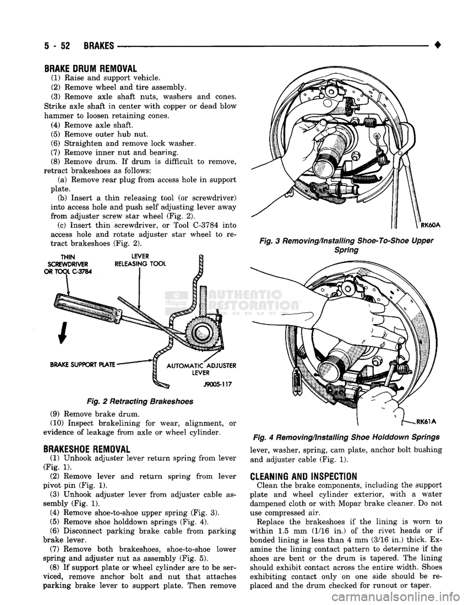
retract brakeshoes as follows: (a) Remove rear plug from access hole in support
plate. (b) Insert a thin releasing tool (or screwdriver)
into access hole and push self adjusting lever away
from adjuster screw star wheel (Fig. 2). (c) Insert thin screwdriver, or Tool C-3784 into
access hole and rotate adjuster star wheel to re
tract brakeshoes (Fig. 2).
Fig.
2 Retracting
Brakeshoes
(9) Remove brake drum.
(10) Inspect brakelining for wear, alignment, or
evidence of leakage from axle or wheel cylinder.
BRAKESHOE
REMOVAL
(1) Unhook adjuster lever return spring from lever
(Fig. 1). (2) Remove lever and return spring from lever
pivot pin (Fig. 1). (3) Unhook adjuster lever from adjuster cable as
sembly (Fig. 1). (4) Remove shoe-to-shoe upper spring (Fig. 3).
(5)
Remove shoe holddown springs (Fig. 4).
(6)
Disconnect parking brake cable from parking
brake lever. (7) Remove both brakeshoes, shoe-to-shoe lower
spring and adjuster nut as assembly (Fig. 5). (8) If support plate or wheel cylinder are to be ser
viced, remove anchor bolt and nut that attaches
parking brake lever to support plate. Then remove
RK60A
Fig.
3 Removing/Installing
Shoe-To-Shoe
Upper
Spring
Fig.
4 Removing/Installing
Shoe
Holddown
Springs
lever, washer, spring, cam plate, anchor bolt bushing and adjuster cable (Fig. 1).
CLEANING AND INSPECTION
Clean the brake components, including the support
plate and wheel cylinder exterior, with a water dampened cloth or with Mopar brake cleaner. Do not
use compressed air. Replace the brakeshoes if the lining is worn to
within 1.5 mm (1/16 in.) of the rivet heads or if
bonded lining is less than 4 mm (3/16 in.) thick. Ex amine the lining contact pattern to determine if the
shoes are bent or the drum is tapered. The lining
should exhibit contact across the entire width. Shoes
exhibiting contact only on one side should be re
placed and the drum checked for runout or taper.
Page 256 of 1502
•
CLUTCH
6 - 3 Check condition of the clutch before installation. A
warped cover or diaphragm spring will cause grab and incomplete release or engagement.
Be careful when handling the cover and disc. Im
pact can distort the cover, diaphragm spring, release
fingers and the hub of the clutch disc.
Use an alignment tool when positioning the disc on
the flywheel. The tool prevents accidental misalign ment which could result in cover distortion and disc
damage.
A frequent cause of clutch cover distortion (and
consequent misalignment) is improper bolt tighten
ing. To avoid warping the cover, tighten the bolts al
ternately (in a diagonal pattern) and evenly (2-3
threads at a time) to specified torque.
Clutch
Housing
Misalignment And Runout Clutch housing alignment is important to proper
operation. The housing bore maintains alignment be
tween the crankshaft and transmission input shaft.
Misalignment can cause noise, incomplete clutch
release and chatter. It can also result in premature
wear of the pilot bearing, cover release fingers and
clutch disc. In severe cases, misalignment can also cause premature wear of the transmission input
shaft and bearing.
Housing face misalignment is generally caused by
incorrect seating on the engine or transmission, loose
housing bolts, missing alignment dowels or housing damage. Infrequently, misalignment may also be
caused by housing mounting surfaces that are not
parallel. If housing misalignment is suspected, housing bore
and face runout can be checked with a dial indicator
as described in the following two procedures:
MEASURING
CLUTCH HOUSING BORE
RUNOUT
(1) Remove the clutch housing and strut.
(2) Remove the clutch cover and disc.
(3) Replace one of the flywheel bolts with a 7/16-20
threaded rod that is 10 in. (25.4 cm) long (Fig. 1).
The rod will be used to mount the dial indicator.
(4) Remove the release fork from the clutch hous
ing. (5) Reinstall the clutch housing. Tighten the hous
ing bolts nearest the alignment dowels first. (6) Mount the dial indicator on the threaded rod
and position the indicator plunger on the surface of
the clutch housing bore (Fig. 2).
(7) Rotate the crankshaft until the indicator
plunger is at the top center of the housing bore. Zero the indicator at this point.
(8) Rotate the crankshaft and record the indicator
readings at eight points (45° apart) around the bore (Fig. 3). Repeat the measurement at least twice for
accuracy. (9) Subtract each reading from the one 180° oppo
site to determine magnitude and direction of runout.
Refer to Figure 3 and following example.
Bore runout example: 0.000 - (-0.007) = 0.007 in. + 0.002 - (-0.010) = 0.012 in.
+ 0.004 - (-0.005) = 0.009 in.
-0.001 -
(
+ 0.001) = -0.002 in. (= 0.002 inch)
In the above example, the largest difference is
0.012 in. and is called the total indicator reading
(TIR).
This means that the housing bore is offset
from the crankshaft centerline by 0.006 in. (which is 1/2 of 0.012 in.).
On gas engines, the acceptable maximum TIR for
housing bore runout is 0.010 inch. If measured TIR is more than 0.010 in. (as in the example), bore runout
will have to be corrected with offset dowels. Offset dowels are available in 0.007, 0.014 and 0.021 in.
sizes for this purpose (Fig. 4). Refer to Correcting
Housing Bore Runout for dowel installation.
On diesel engines, the acceptable maximum
TIR for housing bore runout is 0.015 inch. How
ever, unlike gas engines, offset dowels are not available to correct runout on diesel engines. If
bore runout exceeds the stated maximum on a diesel engine, it may be necessary to replace ei
ther the clutch housing, or transmission adapter
plate.
CORRECTING CLUTCH HOUSING BORE
RUNOUT
(GAS
ENGINE
ONLY)
On gas engine vehicles, clutch housing bore runout
is corrected with offset dowels. However, if bore
runout exceeds 0.015 in. TIR on a diesel equipped model, the clutch housing, or transmission adapter
plate may have to be replaced. Offset dowels are not available for diesel models.
The dial indicator reads positive when the plunger
moves inward (toward indicator) and negative when it moves outward (away from indicator). As a result,
the lowest or most negative reading determines the
direction of housing bore offset (runout).
In the sample readings shown in Figure 3 and in
step (7) above, the bore is offset toward the 0.010
inch reading. To correct this, remove the housing and
original dowels. Then install the new offset dowels in
the direction needed to center the bore with the crankshaft centerline.
In the example, TIR was 0.012 inch. The dowels
needed for correction would have an offset of 0.007
in. (Fig. 4).
Install the dowels with the slotted side facing out
so they can be turned with a screwdriver. Then in
stall the housing, remount the dial indicator and
check bore runout again. Rotate the dowels until the
TIR is less than 0.010 in. if necessary.
If a TIR of 0.053 in. or greater is encountered, it
may be necessary to replace the clutch housing.