1993 DODGE TRUCK four wheel drive
[x] Cancel search: four wheel drivePage 54 of 1502
•
FRONT SUSPENSION
AND
AXLE
2 - 1
CONTENTS
page
FRONT SUSPENSION—2WD VEHICLES
......
7
FRONT SUSPENSION—4WD VEHICLES
14
FRONT WHEEL
ALIGNMENT
...............
3
GENERAL INFORMATION
1
page
MODEL
44
FRONT AXLE
17
MODEL
80
FRONT AXLE
49
TORQUE SPECIFICATIONS
75
GENERAL
INFORMATION
FRONT SUSPENSION—2WD VEHICLES
All two-wheel drive (2WD)
Ram
Truck
and
Ram
charger vehicles
are
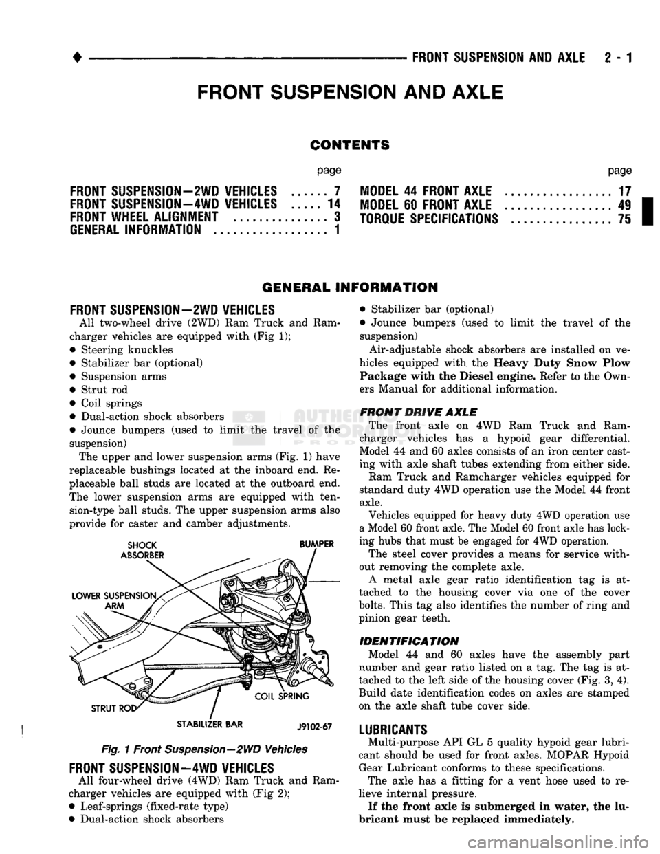
equipped with (Fig
1);
• Steering knuckles
• Stabilizer
bar
(optional) • Suspension arms
• Strut
rod
• Coil springs
• Dual-action shock absorbers
• Jounce bumpers (used
to
limit
the
travel
of the
suspension) The upper and lower suspension arms (Fig.
1)
have
replaceable bushings located
at the
inboard end.
Re
placeable ball studs
are
located
at
the
outboard end.
The lower suspension arms
are
equipped with ten sion-type ball studs. The upper suspension arms also
provide
for
caster
and
camber adjustments.
STABILIZER
BAR
J9102-67
Fig. 1 Front Suspension—2WD Vehicles
FRONT SUSPENSION—4WD VEHICLES
All four-wheel drive (4WD) Ram Truck
and
Ram
charger vehicles
are
equipped with (Fig
2);
• Leaf-springs (fixed-rate type)
• Dual-action shock absorbers • Stabilizer
bar
(optional)
• Jounce bumpers (used
to
limit
the
travel
of the
suspension)
Air-adjustable shock absorbers
are
installed
on
ve
hicles equipped with
the
Heavy Duty Snow Plow Package with
the
Diesel engine. Refer
to
the Own
ers Manual
for
additional information.
FRONT DRIVE AXLE The front axle
on 4WD Ram
Truck
and
Ram
charger vehicles
has a
hypoid gear differential.
Model
44
and
60
axles consists
of
an iron center cast
ing with axle shaft tubes extending from either side.
Ram Truck
and
Ramcharger vehicles equipped
for
standard duty 4WD operation use
the
Model
44
front
axle.
Vehicles equipped
for
heavy duty 4WD operation
use
a Model 60 front axle. The Model 60 front axle has lock
ing hubs that must
be
engaged
for
4WD operation.
The steel cover provides
a
means
for
service with
out removing
the
complete axle. A metal axle gear ratio identification
tag is at
tached
to the
housing cover
via one of the
cover
bolts.
This
tag
also identifies
the
number
of
ring and
pinion gear teeth.
IDENTIFICATION Model
44 and 60
axles have
the
assembly part
number
and
gear ratio listed
on a
tag. The
tag
is at
tached
to
the
left side
of
the housing cover (Fig.
3,
4).
Build date identification codes
on
axles
are
stamped
on
the
axle shaft tube cover side.
LUBRICANTS
Multi-purpose API
GL
5
quality hypoid gear lubri
cant should
be
used
for
front axles. MOPAR Hypoid Gear Lubricant conforms
to
these specifications. The axle
has a
fitting
for a
vent hose used
to re
lieve internal pressure. If the front axle
is
submerged
in
water,
the
lu
bricant must
be
replaced immediately.
FRONT
SUSPENSION
AND
AXLE
Page 81 of 1502
2 - 28
FRONT
SUSPENSION
AND
AXLE
DISCONNECT
AXLE/SHIFT
MOTOR
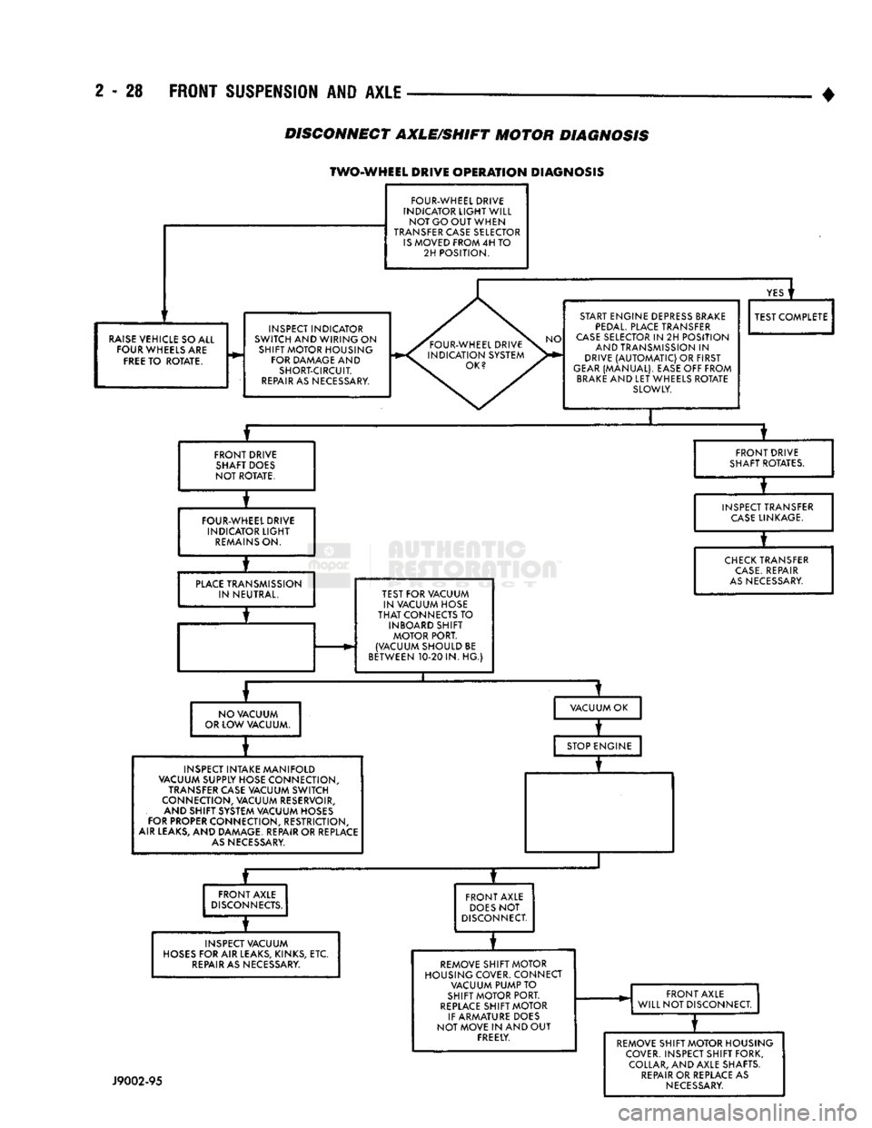
DIAGNOSIS
TWO-WHEEL DRIVE
OPERATION
DIAGNOSIS
FOUR-WHEEL DRIVE
INDICATOR
LIGHT
WILL NOT GO OUT WHEN
TRANSFER CASE SELECTOR
IS
MOVED FROM 4H TO 2H POSITION.
RAISE
VEHICLE SO ALL FOUR WHEELS ARE
FREE
TO ROTATE. INSPECT INDICATOR
SWITCH AND WIRING ON SHIFT MOTOR HOUSING FOR DAMAGE AND SHORT-CIRCUIT.
REPAIR
AS NECESSARY.
YES
i
START ENGINE DEPRESS BRAKE
PEDAL.
PLACE TRANSFER
CASE
SELECTOR IN 2H POSITION AND TRANSMISSION IN
DRIVE
(AUTOMATIC)
OR FIRST
GEAR
(MANUAL). EASE OFF FROM
BRAKE
AND LET WHEELS ROTATE SLOWLY. TEST COMPLETE
FRONT DRIVE SHAFT DOES
NOT ROTATE. FRONT DRIVE
SHAFT ROTATES.
FOUR-WHEEL DRIVE INDICATOR
LIGHT
REMAINS
ON. INSPECT TRANSFER
CASE
LINKAGE.
PLACE
TRANSMISSION IN NEUTRAL. TEST FOR VACUUM
IN VACUUM HOSE
THAT
CONNECTS TO INBOARD SHIFT MOTOR PORT.
(VACUUM SHOULD BE
BETWEEN 10-20 IN. HG.)
CHECK
TRANSFER
CASE.
REPAIR
AS
NECESSARY.
NO VACUUM
OR LOW VACUUM. VACUUM OK
INSPECT INTAKE MANIFOLD
VACUUM SUPPLY HOSE CONNECTION,
TRANSFER CASE VACUUM SWITCH
CONNECTION, VACUUM RESERVOIR, AND SHIFT SYSTEM VACUUM HOSES
FOR PROPER CONNECTION, RESTRICTION,
AIR LEAKS, AND DAMAGE. REPAIR OR REPLACE
AS
NECESSARY. STOP ENGINE
—r~
FRONT AXLE
DISCONNECTS.
INSPECT VACUUM
HOSES
FOR AIR LEAKS, KINKS, ETC.
REPAIR
AS NECESSARY. FRONT AXLE
DOES
NOT
DISCONNECT.
REMOVE SHIFT MOTOR
HOUSING COVER. CONNECT VACUUM PUMP TO
SHIFT MOTOR PORT.
REPLACE
SHIFT MOTOR
IF ARMATURE DOES
NOT MOVE IN AND OUT FREELY. FRONT AXLE
WILL NOT DISCONNECT.
J9002-95
REMOVE SHIFT MOTOR HOUSING
COVER. INSPECT SHIFT FORK, COLLAR, AND AXLE SHAFTS.
REPAIR
OR REPLACE AS
NECESSARY
Page 82 of 1502
FRONT
SUSPENSION AND
AXLE
2 - 29
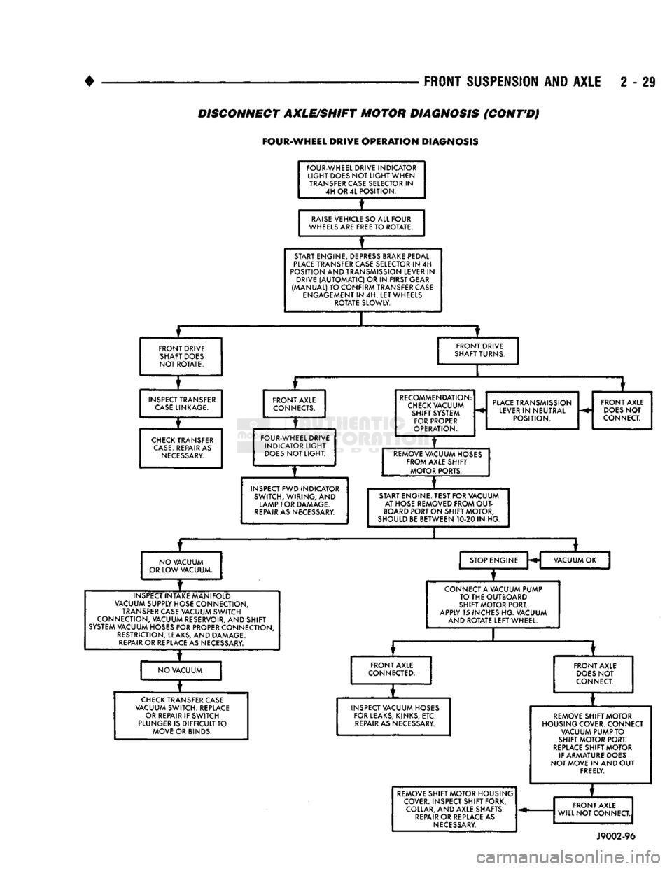
DISCONNECT AXLE/SHIFT MOTOR DIAGNOSIS
(CONT'D)
FOUR-WHEEL
DRIVE
OPERATION
DIAGNOSIS
FOUR-WHEEL DRIVE INDICATOR
LIGHT
DOES NOT
LIGHT
WHEN TRANSFER CASE SELECTOR IN 4H OR 4L POSITION.
RAISE
VEHICLE SO ALL FOUR
WHEELS ARE FREE TO ROTATE.
START ENGINE, DEPRESS BRAKE PEDAL.
PLACE
TRANSFER CASE SELECTOR IN 4H
POSITION AND TRANSMISSION LEVER IN DRIVE
(AUTOMATIC)
OR IN FIRST GEAR
(MANUAL) TO CONFIRM TRANSFER CASE ENGAGEMENT IN 4H. LET WHEELS ROTATE SLOWLY.
FRONT DRIVE SHAFT DOES
NOT ROTATE. FRONT DRIVE
SHAFT TURNS.
INSPECT TRANSFER
CASE
LINKAGE.
CHECK
TRANSFER
CASE.
REPAIR AS
NECESSARY.
FRONT AXLE
CONNECTS.
FOUR-WHEEL DRIVE INDICATOR
LIGHT
DOES
NOT LIGHT.
INSPECT FWD INDICATOR SWITCH, WIRING, AND
LAMP FOR DAMAGE.
REPAIR
AS NECESSARY. RECOMMENDATION:
CHECK
VACUUM SHIFT SYSTEM FOR PROPER
OPERATION.
PLACE
TRANSMISSION
LEVER IN NEUTRAL POSITION. FRONT AXLE
DOES
NOT
CONNECT.
REMOVE VACUUM HOSES FROM AXLE SHIFT MOTOR PORTS.
START ENGINE. TEST FOR VACUUM AT HOSE REMOVED FROM
OUT
BOARD
PORT ON SHIFT MOTOR,
SHOULD BE BETWEEN 10-20 IN HG.
NO VACUUM
OR LOW VACUUM. STOP ENGINE
H VACUUM OK
INSPECT INTAKE MANIFOLD
VACUUM SUPPLY HOSE CONNECTION, TRANSFER CASE VACUUM SWITCH
CONNECTION, VACUUM RESERVOIR, AND SHIFT
SYSTEM VACUUM HOSES FOR PROPER CONNECTION, RESTRICTION, LEAKS, AND DAMAGE.
REPAIR
OR REPLACE AS NECESSARY. CONNECT A VACUUM PUMP
TO THE OUTBOARD
SHIFT MOTOR PORT.
APPLY 15 INCHES HG. VACUUM AND ROTATE LEFT WHEEL.
NO VACUUM FRONT AXLE
CONNECTED.
CHECK
TRANSFER CASE
VACUUM SWITCH. REPLACE OR REPAIR IF SWITCH
PLUNGER IS DIFFICULT TO MOVE OR BINDS. FRONT AXLE
DOES
NOT
CONNECT.
INSPECT VACUUM HOSES FOR LEAKS, KINKS, ETC.
REPAIR
AS NECESSARY. REMOVE SHIFT MOTOR
HOUSING COVER. CONNECT VACUUM PUMP TO
SHIFT MOTOR PORT.
REPLACE
SHIFT MOTOR
IF ARMATURE DOES
NOT MOVE IN AND OUT FREELY. REMOVE SHIFT MOTOR HOUSING
COVER. INSPECT SHIFT FORK, COLLAR, AND AXLE SHAFTS.
REPAIR
OR REPLACE AS
NECESSARY.
*
REMOVE SHIFT MOTOR HOUSING
COVER. INSPECT SHIFT FORK, COLLAR, AND AXLE SHAFTS.
REPAIR
OR REPLACE AS
NECESSARY.
FRONT AXLE
WILL NOT CONNECT.
REMOVE SHIFT MOTOR HOUSING
COVER. INSPECT SHIFT FORK, COLLAR, AND AXLE SHAFTS.
REPAIR
OR REPLACE AS
NECESSARY.
FRONT AXLE
WILL NOT CONNECT.
REMOVE SHIFT MOTOR HOUSING
COVER. INSPECT SHIFT FORK, COLLAR, AND AXLE SHAFTS.
REPAIR
OR REPLACE AS
NECESSARY.
J9002-96
Page 205 of 1502
LET.
TORQUE
LET. POUNDS
NEWTON
METRES
145 IN. 16
125 IN. 14
100 IN. 11
170 IN. 19
SCREW
RIGHT
BRAKE
TUBE
RIGHT
BRAKE
TUBE
BRAKE HOSE BRAKE
VALVE
TUBE
TO
FRONT
BRAKE HOSE
VALVE
VIEW
IN
DIRECTION
OF
ARROW
B
ASSEMBLY
8905-55
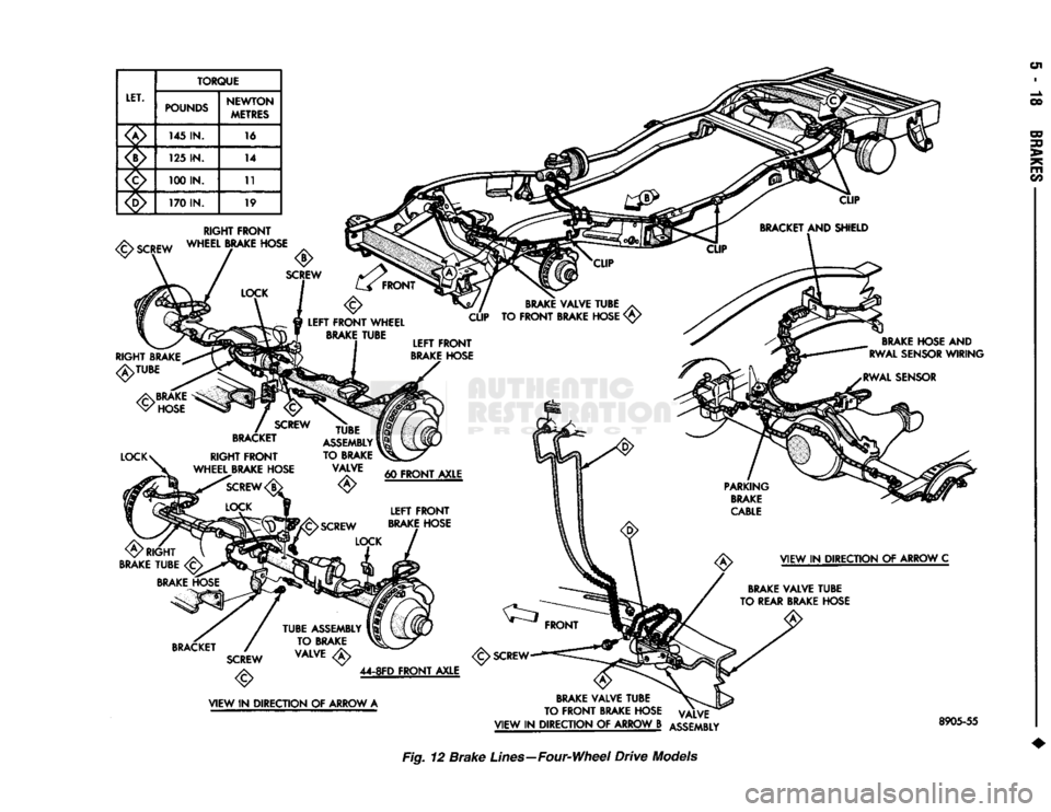
Fig. 12 Brake Lines—Four-Wheel Drive Models
Page 393 of 1502
8E
- 12
INSTRUMENT PANEL
AND
GAUGES
•
CLUSTER AND GAUGE
SERVICE
PROCEDURES
INDEX
page
Cluster Bezel
12
Cluster
Mask
and
Lens
12
Fuel Gauge
13
Instrument
Cluster Assembly
12
Lamp Bulb Replacement—Message Center
..... 15
CLUSTER
BEZEL
REMOVAL
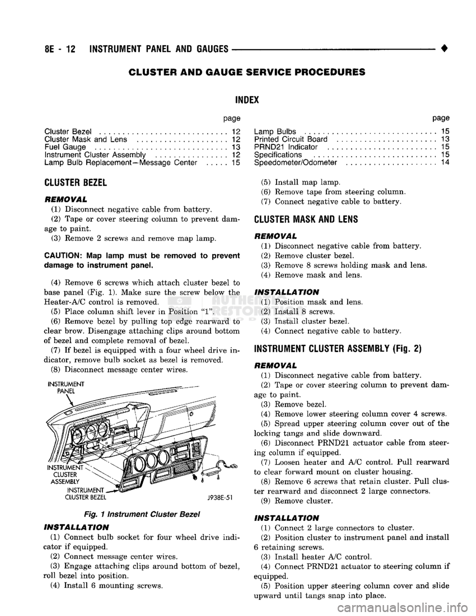
(1) Disconnect negative cable from battery.
(2) Tape
or
cover steering column
to
prevent dam
age
to
paint.
(3) Remove
2
screws and remove map lamp.
CAUTION:
Map
lamp must
be
removed
to
prevent
damage
to
instrument panel.
(4) Remove
6
screws which attach cluster bezel
to
base panel (Fig.
1).
Make sure
the
screw below
the
Heater-A/C control
is
removed.
(5)
Place column shift lever
in
Position
"1".
(6) Remove bezel
by
pulling
top
edge rearward
to
clear brow. Disengage attaching clips around bottom
of bezel
and
complete removal
of
bezel.
(7)
If
bezel
is
equipped with
a
four wheel drive
in
dicator, remove bulb socket
as
bezel
is
removed.
(8) Disconnect message center wires.
INSTRUMENT
CLUSTER BEZEL
J938E-51
Fig.
1 instrument
Cluster
Bezel
INSTALLATION
(1) Connect bulb socket
for
four wheel drive indi
cator
if
equipped.
(2)
Connect message center wires.
(3) Engage attaching clips around bottom
of
bezel,
roll bezel into position.
(4) Install
6
mounting screws. page
Lamp Bulbs
. . 15
Printed
Circuit
Board
13
PRND21
Indicator
. 15
Specifications
15
Speedometer/Odometer
14
(5)
Install map lamp.
(6) Remove tape from steering column.
(7) Connect negative cable
to
battery.
CLUSTER
MASK AND LENS REMOVAL
(1) Disconnect negative cable from battery.
(2) Remove cluster bezel.
(3) Remove
8
screws holding mask
and
lens.
(4) Remove mask
and
lens.
INSTALLATION
(1) Position mask
and
lens.
(2) Install
8
screws.
(3) Install cluster bezel.
(4) Connect negative cable
to
battery.
INSTRUMENT CLUSTER ASSEMBLY
(Fig.
2)
REMOVAL
(1) Disconnect negative cable from battery.
(2) Tape
or
cover steering column
to
prevent dam
age
to
paint.
(3) Remove bezel.
(4) Remove lower steering column cover
4
screws.
(5)
Spread upper steering column cover
out of
the
locking tangs
and
slide downward. (6) Disconnect PRND21 actuator cable from steer
ing column
if
equipped.
(7) Loosen heater
and
A/C control. Pull rearward
to clear forward mount
on
cluster housing.
(8) Remove
6
screws that retain cluster. Pull clus
ter rearward
and
disconnect
2
large connectors.
(9) Remove cluster.
INSTALLATION
(1) Connect
2
large connectors
to
cluster.
(2) Position cluster
to
instrument panel and install
6 retaining screws.
(3) Install heater A/C control.
(4) Connect PRND21 actuator
to
steering column
if
equipped.
(5)
Position upper steering column cover
and
slide
upward until tangs snap into place.
Page 396 of 1502
•
INSTRUMENT PANEL
AND
GAUGES
8E - 15
PRND21 INDICATOR
REMOVAL
(1) Remove bezel. Refer to Cluster Bezel Removal.
(2)
Remove cluster mask and lens. Refer to Cluster
Mask and Lens Removal. (3) Remove cluster assembly. Refer to Instrument
Cluster Removal. (4) Remove screws attaching PRND21 mechanism
to cluster housing.
(5)
Remove PRND21 mechanism.
INSTALLATION (1) Position PRND21 mechanism to cluster hous
ing. (2) Install mounting screws.
(3)
Install cluster assembly. (4) Install mask-lens.
(5)
Install bezel.
LAMP BULBS
CLUSTER ILLUMINATION LAMPS TURN SIGNAL INDICATOR LAMPS
LOW OIL PRESSURE INDICATOR LAMP
HIGH BEAM INDICATOR LAMP CHECK ENGINE LAMP
SEAT BELT WARNING LAMP
REMOVAL (1) Disconnect negative cable from battery.
(2) Remove instrument cluster. See cluster re
moval.
(3)
Twist lamp socket assembly and remove from
printed circuit board. (4) Remove bulb from socket.
INSTALLATION (1) Install bulb into socket.
(2) Install socket assembly into printed circuit
board.
(3)
Position cluster into place in panel. See cluster
installation. (4) Connect battery negative cable.
LAMP BULB REPLACEMENT—MESSAGE CENTER
REMOVAL (1) Disconnect battery negative cable.
(2) Remove instrument cluster bezel assembly. Re
fer to Instrument Cluster removal.
(3)
Twist lamp socket assembly and remove from
printed circuit board. (4) Remove bulb from socket.
INSTALLATION (1) Install bulb into socket assembly. (2) Install lamp socket assembly into printed cir
cuit board.
(3)
Install Instrument Cluster bezel assembly to
instrument panel. Refer to Instrument Cluster instal
lation.
(4) Connect negative cable from battery.
FOUR WHEEL DRIVE INDICATOR LAMP (1) Pull bulb and socket assembly from rear of
housing. (2) Remove bulb from socket.
(3)
Reverse removal procedures to install.
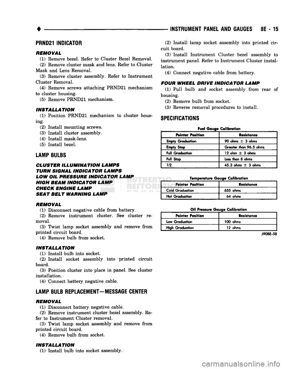
SPECIFICATIONS
Fuel
Gauge Calibration
Mntar Position Resistance
Empty Graduation 90
ohms
± 3
ohms
Empty Stop
Greater
than
96.5 ohms
Full
Graduation 12 ohm
± 3
ohms
Full
Stop
Less
than
8
ohms
1/2
45.3 ohms
± 3
ohms
Temperature
Gauge
Calibration
Pointer
Position Resistance
Cold Graduation 655 ohms
Hot Graduation 64 ohms
Oil Pressure Gauge Calibration
Pointer
Position Resistance
Low Graduation 100 ohms
High Graduation 12 ohms
J908E-58
Page 397 of 1502
8E - 16 INSTRUMENT PANEL AND GAUGES
• SWITCH AND
PANEL
COMPONENT
SERVICE
INDEX
page
Ash
Tray
20
Cigar
Lighter
........................ 20
Four
Wheel Drive
Indicator
19
Fuse
Block
and
Flashers
................... 19
Glove
Box 21
Heater A/C Control
17
page
Heater Control
16
Hood
Release
19
Illumination
Bulb Replacement
22
Message
Center Module
................... 18
Steering Column Lowering
and
Raising
16
Switches
17
DISCONNECT NEGATIVE CABLE FEOM
BATTERY IN ENGINE COMPAETMENT BE FORE SERVICING INSTRUMENT PANEL.
STEERING COLUMN LOWERING AND RAISING When servicing the instrument panel and the Low
ering and Raising of the steering column is required,
the following is the procedure for doing so: This procedure is not for removing and replac
ing the steering column. Refer to Group - 19 Steering of this manual for the removal and re
placement procedures.
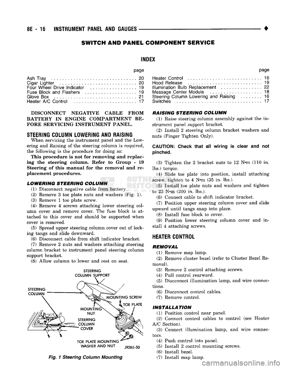
LOWERING STEERING COLUMN
(1) Disconnect negative cable from battery.
(2)
Remove 3 toe plate nuts and washers (Fig. 1).
(3) Remove 1 toe plate screw.
(4) Remove 4 screws attaching lower steering col
umn cover and remove cover. The fuse block is at
tached to this cover and should be supported when cover is removed.
(5) Spread upper steering column cover out of lock
ing tangs and slide downward.
(6)
Disconnect cable from shift indicator bracket.
(7)
Remove 2 nuts and washers attaching steering
column bracket to instrument panel steering column support bracket.
(8)
Allow column to lower and rest on seat.
STEERING
COLUMN SUPPORT
WASHER
AND NUT
Fig.
1 Steering
Column
Mounting
RAISING STEERING COLUMN
(1) Raise steering column assembly against the in
strument panel support bracket. (2) Install 2 steering column bracket washers and
nuts (Finger Tighten Only).
CAUTION:
Check that
all
wiring
is
clear
and not
pinched.
(3) Tighten the 2 bracket nuts to 12 Nnn-(110 in.
lbs.) torque. (4) Slide toe plate into position, install attaching
screw, tighten to 4 N®m (35 in. lbs.).
(5) Install toe plate nuts and washers and tighten
to 23 N*m (200 in. lbs.).
(6)
Connect cable to shift indicator bracket.
(7)
Position upper steering column cover and slide
upward until tangs snap into place.
(8) Install fuse block to cover.
(9)
Position lower steering column cover and in
stall 4 attaching screws.
HEATER CONTROL
REMOVAL
(1) Remove map lamp.
(2) Remove cluster bezel (refer to Cluster Bezel Re
moval). (3) Remove 2 control attaching screws. (4) Pull control rearward.
(5) Disconnect illumination lamp, and wire connec
tions.
(6)
Disconnect control cables.
(7)
Remove control.
INSTALLATION
(1) Position control near panel.
(2) Connect control cables to control (see Heater
A/C Section). (3) Connect illumination lamp, and wire connec
tors.
(4) Push control into panel.
(5) Install 2 control mounting screws.
(6)
Install bezel.
(7)
Install map lamp.
Page 400 of 1502
•
INSTRUMENT PANEL
AND
GAUGES
8E - 19
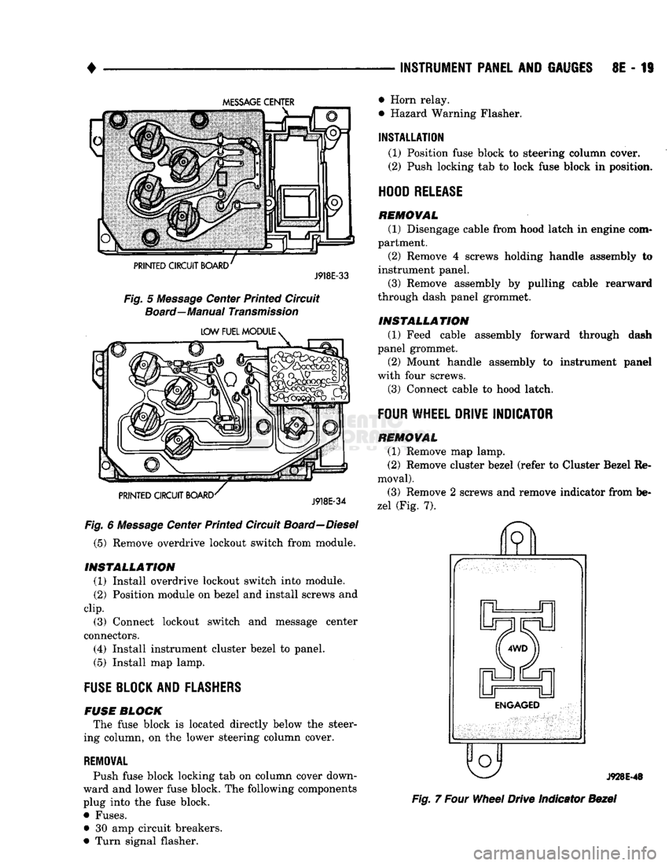
MESSAGE
CENTER
PRINTED CIRCUIT BOARD
J918E-33
Fig.
5
Message
Center Printed Circuit
Board—Manual
Transmission
LOW FUEL MODULE
>
PRINTED CIRCUIT BOARD
J918E-34
Fig.
6
Message
Center Printed Circuit
Board—Diesel
(5) Remove overdrive lockout switch from module.
INSTALLATION
(1) Install overdrive lockout switch into module.
(2) Position module on bezel and install screws and
clip.
(3) Connect lockout switch and message center
connectors.
(4) Install instrument cluster bezel to panel.
(5) Install map lamp.
FUSE
BLOCK AND
FLASHERS
FUSE
BLOCK
The fuse block is located directly below the steer
ing column, on the lower steering column cover.
REMOVAL
Push fuse block locking tab on column cover down
ward and lower fuse block. The following components
plug into the fuse block.
• Fuses. • 30 amp circuit breakers.
• Turn signal flasher. • Horn relay.
• Hazard Warning Flasher.
INSTALLATION
(1) Position fuse block to steering column cover. (2) Push locking tab to lock fuse block in position.
HOOD
RELEASE
REMOVAL
(1) Disengage cable from hood latch in engine com
partment. (2) Remove 4 screws holding handle assembly to
instrument panel.
(3) Remove assembly by pulling cable rearward
through dash panel grommet.
INSTALLATION
(1) Feed cable assembly forward through dash
panel grommet.
(2) Mount handle assembly to instrument panel
with four screws.
(3) Connect cable to hood latch.
FOUR
WHEEL
DRIVE
INDICATOR
REMOVAL
(1) Remove map lamp.
(2) Remove cluster bezel (refer to Cluster Bezel Re
moval).
(3) Remove 2 screws and remove indicator from be
zel (Fig. 7).
o
J928E-48
Fig.
7
Four
Wheel
Drive Indicator
Bezel