8K
- 10
WINDSHIELD WIPER
AND
WASHER SYSTEMS
• (2) Mount multifunction switch
to
column
and (4)
Install tilt lever (tilt column only),
torque retaining screws
to 2 N»m (17 in.
lbs.).
(5)
Install battery cable. (3) Install steering column covers. Torque retain-
(6)
Check
all
functions
of
switch
for
proper opera-
ing screws
to 2 N»m (17 in.
lbs.). tion.
WINDSHIELD
WASHERS
GENERAL INFORMATION
All models
are
equipped with electric operated
windshield washer pumps. The electric pump assembly
is
mounted directly
to
the reservoir.
A
permanently lubricated sealed motor is coupled
to a
rotor type pump. Fluid, gravity
fed
from
the
reservoir,
is
forced
by the
pump through rubber hoses
to the
nozzles which direct
the
streams
to
the
windshield. These vehicles
are
equipped with special plastic
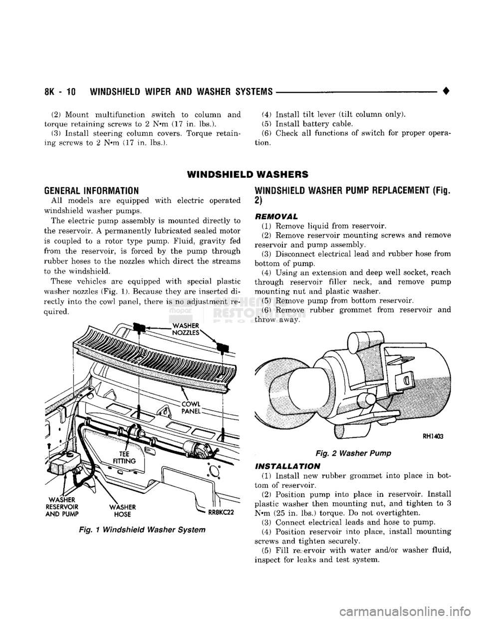
washer nozzles
(Fig. 1).
Because they
are
inserted
di
rectly into
the
cowl panel, there
is no
adjustment
re
quired.
Fig.
1
Windshield
Washer
System
WINDSHIELD WASHER PUMP REPLACEMENT
(Fig.
2)
REMOVAL (1) Remove liquid from reservoir.
(2) Remove reservoir mounting screws
and
remove
reservoir
and
pump assembly. (3) Disconnect electrical lead
and
rubber hose from
bottom
of
pump. (4) Using
an
extension
and
deep well socket, reach
through reservoir filler neck,
and
remove pump
mounting
nut and
plastic washer.
(5)
Remove pump from bottom reservoir.
(6) Remove rubber grommet from reservoir
and
throw away.
Fig.
2
Washer
Pump
INSTALLATION (1) Install
new
rubber grommet into place
in
bot
tom
of
reservoir. (2) Position pump into place
in
reservoir. Install
plastic washer then mounting
nut, and
tighten
to 3
N»m
(25 in. lbs.)
torque.
Do not
overtighten.
(3) Connect electrical leads
and
hose
to
pump.
(4) Position reservoir into place, install mounting
screws
and
tighten securely. (5) Fill reservoir with water and/or washer fluid,
inspect
for
leaks
and
test system.
•
WINDSHIELD WIPER
AND
WASHER SYSTEMS
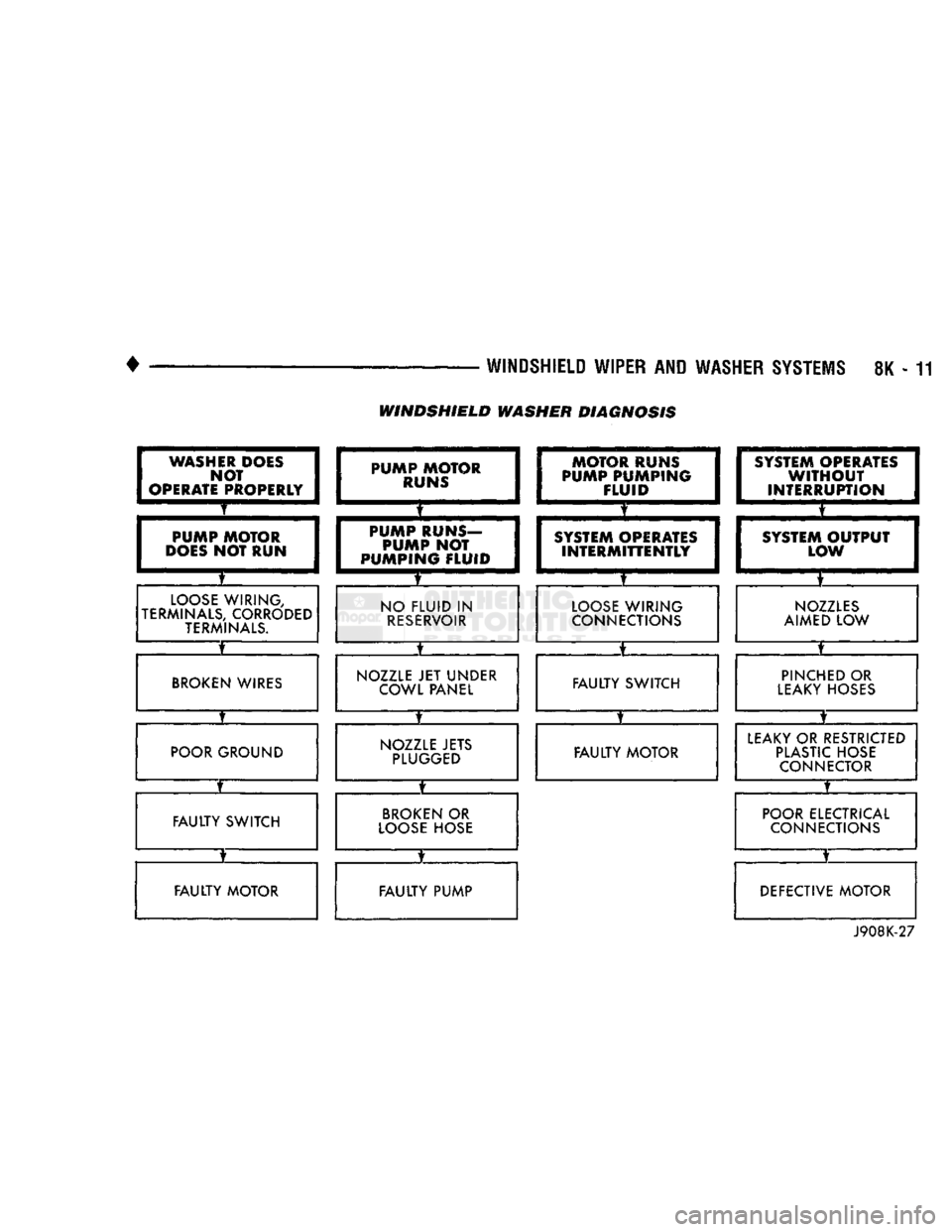
8K - 11 WINDSHIELD WASHER DIAGNOSIS
WASHER DOES NOT
OPERATE PROPERLY
T
PUMP MOTOR
DOES
NOT RUN
LOOSE WIRING,
TERMINALS, CORRODED TERMINALS
X
BROKEN WIRES
POOR GROUND
FAULTY
SWITCH
FAULTY
MOTOR PUMP MOTOR
RUNS
T •
PUMP RUNS-
PUMP
NOT
PUMPING
FLUID
NO
FLUID
IN
RESERVOIR
NOZZLE
JET
UNDER COWL PANEL
NOZZLE JETS PLUGGED
BROKEN
OR
LOOSE HOSE
FAULTY
PUMP MOTOR RUNS
PUMP PUMPING
FLUID
SYSTEM OPERATES
INTERMITTENTLY
LOOSE WIRING
CONNECTIONS
X
FAULTY
SWITCH
t
FAULTY
MOTOR SYSTEM OPERATES
WITHOUT
INTERRUPTION IATES
I
T I
ION
j
SYSTEM
OUTPUT
LOW
NOZZLES
AIMED
LOW
PINCHED
OR
LEAKY HOSES
X
LEAKY
OR
RESTRICTED PLASTIC HOSE CONNECTOR
X
POOR ELECTRICAL CONNECTIONS
DEFECTIVE MOTOR
J908K-27