1993 DODGE TRUCK 4WD
[x] Cancel search: 4WDPage 21 of 1502
0 - 2
LUBRICATION
AND
MAINTENANCE
• Commercial service
When a vehicle is continuously subjected to severe
driving conditions, lubricate:
• Body components
• All the driveline coupling joints
• Steering linkage More often than normal driving conditions
DUSTY
AREAS
With this type of severe driving condition, special
care should be given to the:
• Engine air cleaner filter
• PCV filter
• Crankcase ventilation system
• Brake booster control valve air filter. Verify that the filters and the associated compo
nents are clean. Also verify that they are functioning
effectively. This will minimize the amount of abra sive particles that enter the engine.
OFF-ROAD
(4WD)
OPERATION
After off-road (4WD) operation, inspect the under
side of the vehicle. Inspect the:
• Tires
• Body structure
• Steering components
• Suspension components • Exhaust system
• Threaded fasteners
HARSH
SURFACE ENVIRONMENTS
After extended operation in harsh environments,
the brake drums, brake linings, and rear wheel bear ings should be inspected and cleaned. This will pre
vent wear and erratic brake action.
ROUTINE MAINTENANCE
The following routine maintenance is recommended
on a monthly basis: TIRES—Inspect the tires for unusual wear/damage.
Determine if the inflation pressure is adequate for
the vehicle load. BATTERY—Inspect and clean the terminals.
Tighten the terminals if necessary. FLUIDS—Determine if the component fluid levels
are acceptable. Add fluid, if necessary. LIGHTS/ELECTRICAL—Test all the electrical sys
tems in the vehicle for proper operation. It is also recommended that the engine oil and the
washer fluid level be determined at each fuel fill-up.
VEHICLE
NOISE CONTROL
Vehicles with a GVWR of 4 535 kg (10,000 lbs), or
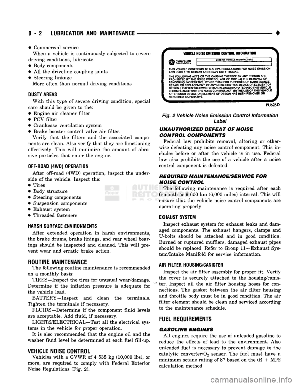
more, are required to comply with Federal Exterior Noise Regulations (Fig. 2).
VEHICLE
NOISE
EMISSION
CONTROL INFORMATION
DATE
OF
VEHICLE
MANUFACTURE
THIS
VEHICLE CONFORMS
TO
U.S. EPA REGULATIONS FOR NOISE EMISSION
APPLICABLE
TO
MEDIUM
AND HEAVY
DUTY
TRUCKS. THE
FOLLOWING
ACTS OR THE CAUSING THEREOF BY ANY PERSON ARE PROHIBITED BY THE NOISE CONTROL ACT
OF 1972. (A) THE
REMOVAL
OR
RENDERING
INOPERATIVE, OTHER
THAN
FOR
PURPOSES
OF
MAINTENANCE,
REPAIR.
OR REPLACEMENT, OF ANY NOISE CONTROL DEVICE OR ELEMENT OF
DESIGN
(LISTED
IN
THE
OWNERS
MANUAL)
INCORPORATED
INTO
THIS
VEHICLE
IN COMPLIANCE
WITH
THE NOISE CONTROL
ACT:
(B) THE
USE
OF
THIS
VEHICLE
AFTER SUCH DEVICE
OR
ELEMENT
OF
DESIGN HAS BEEN REMOVED
OR
RENDERED
INOPERATIVE.
PU626D
Fig.
2 Vehicle
Noise
Emission
Control Information
Label
UNAUTHORIZED
DEFEAT
OF
NOISE
CONTROL COMPONENTS
Federal law prohibits removal, altering or other
wise defeating any noise control component. This in
cludes before or after the vehicle is in use. Federal
law also prohibits the use of a vehicle after a noise
control component is defeated.
REQUIRED MAINTENANCE/SERVICE
FOR
NOISE
CONTROL
The following maintenance is required after each
6-month or 9 600 km (6,000 miles) interval. This will
ensure that the vehicle noise control components are
operating properly.
EXHAUST SYSTEM
Inspect exhaust system for exhaust leaks and dam
aged components. The exhaust hangers, clamps and
U-bolts should be attached and in good condition.
Burned or ruptured mufflers, damaged exhaust pipes should be replaced. Refer to Group 11—Exhaust Sys
tem/Intake Manifold for service information.
AIR
FILTER
HOUSING/CANISTER
Inspect the air filter assembly for proper fit. Verify
the cover is securely attached to the housing/canis
ter. Inspect all the air filter housing hoses for con nections. The gasket between the air filter housing and throttle body must be in good condition. The air
filter element should be clean and serviced according
to the maintenance schedule.
FUEL
REQUIREMENTS
GASOLINE
ENGINES
All engines require the use of unleaded gasoline to
reduce the effects of lead to the environment. Also unleaded fuel is necessary to prevent damage to the
catalytic converter/02 sensor. The fuel must have a
minimum octane rating of 87 based on the (R + M)/2
calculation method.
Page 28 of 1502
•
LUBRICATION AND MAINTENANCE
0 - 9 FLUID CAPACITIES
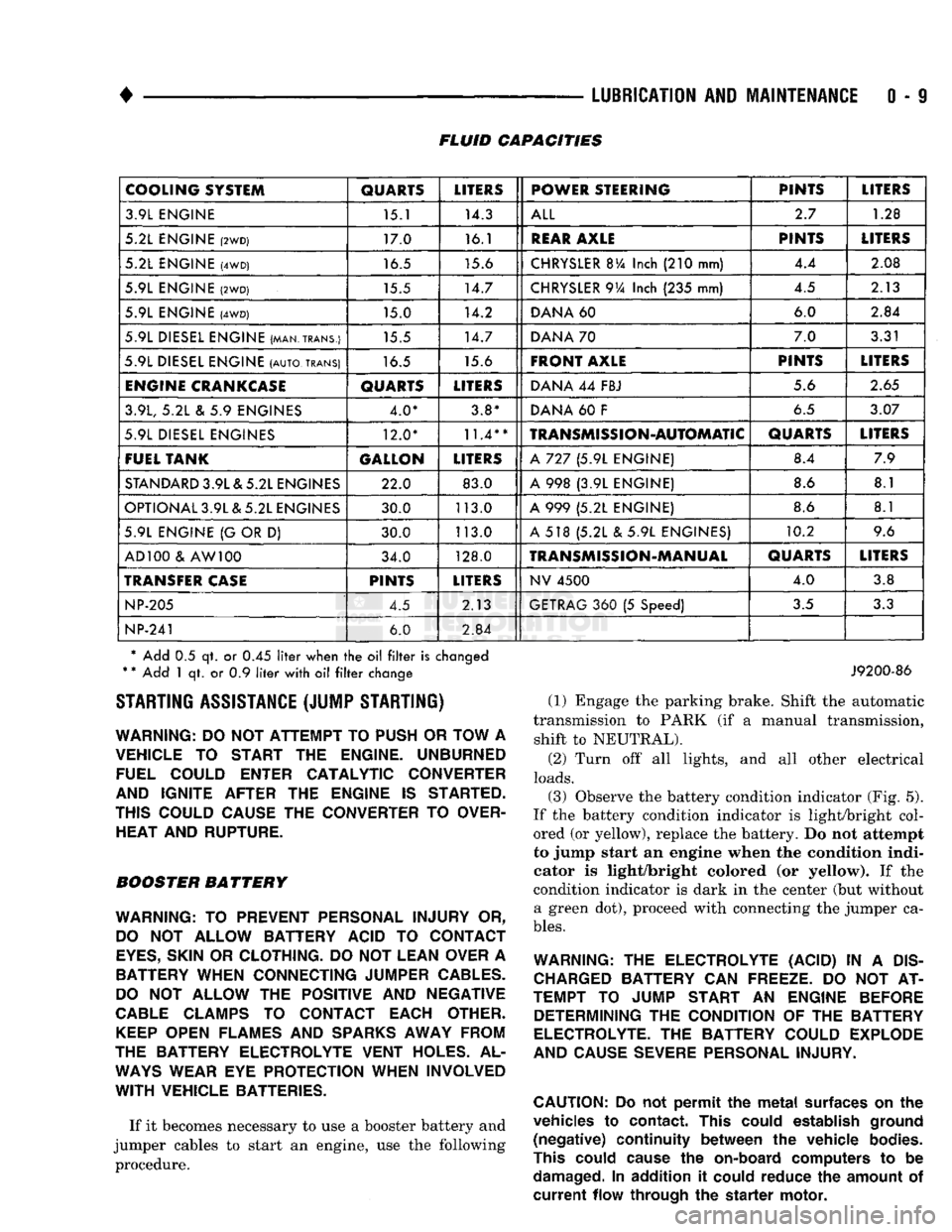
COOLING SYSTEM
QUARTS
LITERS
POWER STEERING PINTS
LITERS
3.9L ENGINE 15.1 14.3
ALL
2.7
1.28
5.2L ENGINE
(2WD)
17.0 16.1
REAR
AXLE
PINTS
LITERS
5.2L ENGINE
(4WD)
16.5 15.6
CHRYSLER
BVa
Inch
(210
mm) 4.4
2.08
5.9L ENGINE
(2WD)
15.5 14.7
CHRYSLER
9Va
Inch
(235
mm) 4.5
2.13
5.9L ENGINE
(4WD)
15.0 14.2
DANA
60 6.0
2.84
5.9L DIESEL ENGINE (MAN.TRANS.) 15.5 14.7
DANA
70 7.0
3.31
5.9L DIESEL ENGINE
(AUTO,
TRANS)
16.5 15.6
FRONT AXLE
PINTS
LITERS
ENGINE
CRANKCASE
QUARTS
LITERS
DANA
44
FBJ 5.6
2.65
3.9L,
5.2L & 5.9
ENGINES 4.0* 3.8*
DANA
60 F
6.5
3.07
5.9L DIESEL ENGINES 12.0*
11.4**
TRANSMISSION-AUTOMATIC
QUARTS
LITERS
FUEL TANK GALLON
LITERS
A
727 (5.9L
ENGINE) 8.4
7.9
STANDARD
3.9L & 5.2L ENGINES 22.0 83.0
A
998 (3.9L
ENGINE) 8.6
8.1
OPTIONAL 3.9L & 5.2L ENGINES 30.0 113.0
A
999 (5.2L
ENGINE) 8.6
8.1
5.9L ENGINE
{G
OR
D)
30.0 113.0
A
518 (5.2L & 5.9L
ENGINES) 10.2
9.6
AD 100
&
AW 100 34.0 128.0
TRANSMISSION-MANUAL
QUARTS
LITERS
TRANSFER
CASE
PINTS
LITERS
NV
4500
4.0
3.8
NP-205
4.5 2.13
GETRAG
360 (5
Speed)
3.5
3.3
NP-241
6.0
2.84
* Add
0.5 qt. or 0.45
liter
when
the oil filter
is
changed
*
*
Add
1 qt. or 0.9
liter
with
oil filter
change STARTING ASSISTANCE (JUMP STARTING)
WARNING:
DO NOT
ATTEMPT
TO
PUSH
OR
TOW
A
VEHICLE
TO
START
THE
ENGINE. UNBURNED FUEL COULD ENTER CATALYTIC CONVERTER
AND IGNITE AFTER
THE
ENGINE
IS
STARTED.
THIS COULD CAUSE
THE
CONVERTER
TO
OVER HEAT AND RUPTURE.
BOOSTER BATTERY
WARNING:
TO
PREVENT PERSONAL INJURY
OR,
DO
NOT
ALLOW BATTERY ACID
TO
CONTACT
EYES,
SKIN
OR
CLOTHING.
DO NOT
LEAN OVER
A
BATTERY WHEN CONNECTING JUMPER
CABLES.
DO
NOT
ALLOW
THE
POSITIVE
AND
NEGATIVE
CABLE
CLAMPS
TO
CONTACT EACH OTHER.
KEEP
OPEN FLAMES
AND
SPARKS
AWAY FROM
THE BATTERY ELECTROLYTE VENT HOLES.
AL
WAYS
WEAR
EYE
PROTECTION WHEN INVOLVED
WITH
VEHICLE BATTERIES.
If it becomes necessary to use a booster battery and
jumper cables to start an engine, use the following procedure.
J9200-86
(1) Engage the parking brake. Shift the automatic
transmission to PARK (if a manual transmission, shift to NEUTRAL).
(2) Turn off all lights, and all other electrical
loads.
(3)
Observe the battery condition indicator (Fig. 5).
If the battery condition indicator is light/bright col
ored (or yellow), replace the battery. Do not attempt
to jump start an engine when the condition indi
cator is light/bright colored (or yellow). If the
condition indicator is dark in the center (but without a green dot), proceed with connecting the jumper ca
bles.
WARNING:
THE
ELECTROLYTE (ACID)
IN A
DIS
CHARGED
BATTERY
CAN
FREEZE.
DO NOT AT
TEMPT
TO
JUMP START
AN
ENGINE BEFORE DETERMINING
THE
CONDITION
OF THE
BATTERY
ELECTROLYTE.
THE
BATTERY COULD EXPLODE
AND CAUSE SEVERE PERSONAL INJURY.
CAUTION:
Do not
permit
the
metal
surfaces
on the
vehicles
to
contact.
This
could
establish
ground
(negative)
continuity
between
the
vehicle
bodies.
This
could
cause
the
on-board
computers
to be
damaged.
In
addition
it
could
reduce
the
amount
of
current
flow
through
the
starter
motor.
Page 30 of 1502

LUBRICATION
AND
MAINTENANCE
0-11
J
DRIVE-ON
HOIST
I
FRAME
CONTACT
HOIST
TWIN
POST
CHASSIS
HOIST
FLOOR
JACK
RROOD30
Fig.
8 Correct Vehicle Lifting
Locations
An axle tube
A body side sill
A steering linkage component
A drive shaft
The engine or transmission oil pan
The fuel tank
• A front suspension arm Use the correct frame rail lifting locations only
(Fig. 8).
HOIST A vehicle can be lifted with:
• A single-post, frame-contact hoist
• A twin-post, chassis hoist
• A ramp-type, drive-on hoist
When a frame-contact type hoist is used, verify
that the lifting pads are positioned properly (Fig. 8).
WARNING:
WHEN
A
SERVICE
PROCEDURE
RE
QUIRES
THE
REMOVAL
OF
THE
REAR
AXLE,
FUEL
TANK,
OR
SPARE
TIRE,
EITHER:
• PLACE ADDITIONAL WEIGHT ON THE REAR
END OF THE VEHICLE
« ATTACH THE VEHICLE TO THE HOIST
« PLACE JACK STANDS UNDER THE VEHICLE
FOR SUPPORT TO PREVENT TIPPING WHEN
THE CENTER OF BALANCE CHANGES
4WD VEHICLES A standard hoist can be used to lift a 4WD vehicle.
The hoist should be inspected for adequate clearance. The lift arms, pads or ramps should be adjusted to
ensure that there is adequate clearance (Fig. 9).
ADJUSTMENT
PAD
ii 7
MAINTAIN
CLEARANCE
HOIST
ARM
RK44
Fig.
9 Lifting 4WD Vehicle
With
Single-Post
Hoist—
Typical
When a twin-post hoist is used, a 4 x 4 x 12-inch
wood spacer also could be required. Place the wood spacer under the front axle (opposite the differential
housing). This will maintain balance and level lift ing.
CAUTION:
The
block
that
is
used must
be
secured in
a
safe manner. This
will
ensure
that
it
will
not un
balance
the
vehicle.
VEHICLE
TOWING
RECOMMENDATIONS
When it is necessary to tow a Ram Truck, the rec
ommended method is either:
• the sling-type, rear-end raised towing method; or
• the wheel-lift towing method with a tow dolly lo
cated under the front wheels. A vehicle with flat-bed hauling equipment can also
be used to transport a disabled vehicle.
SLING-TYPE
FLAT
BED
RR0OD29
Fig.
10 Tow Vehicles
With
Approved
Equipment
Page 41 of 1502
0
- 22
LUBRICATION
AND
MAINTENANCE
DRIVETRAIN
INDEX
page
Axles
25
Clutch
and
Brake Pedal
Bushings
............ 22
Clutch Master Cylinder
22
Drive Shafts
26
page
Front Axle U-Joint
and
Pivot Bearings
......... 26
Transfer
Case
(4WD
Vehicles)
. . ........ 24
Transmissions
. 22
CLUTCH
AND
BRAKE PEDAL
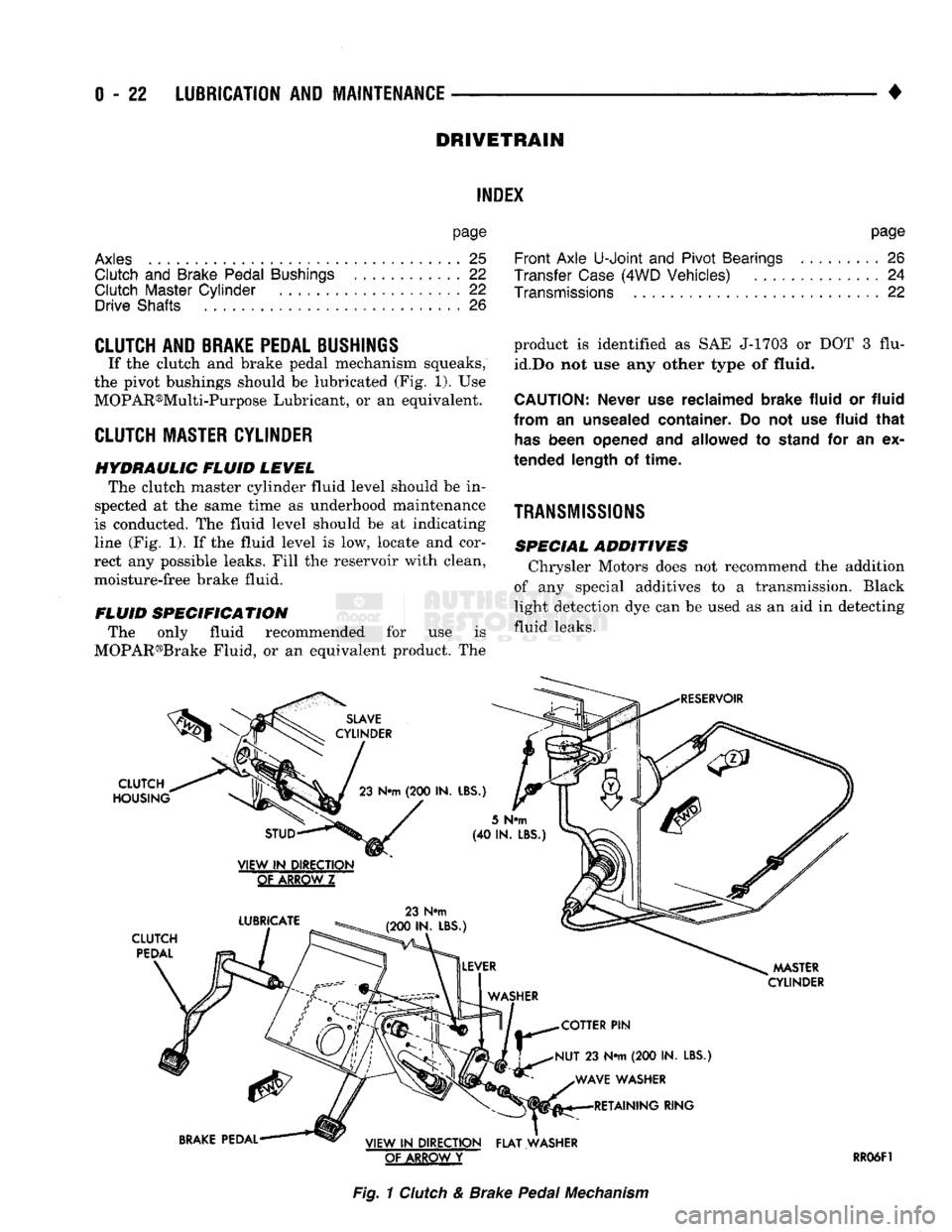
If the clutch and brake pedal mechanism squeaks,
the pivot bushings should be lubricated (Fig. 1). Use
MOPAR®Multi-Purpose Lubricant, or an equivalent.
CLUTCH
MASTER CYLINDER
HYDRAULIC FLUID LEVEL The clutch master cylinder fluid level should be in
spected at the same time as underhood maintenance
is conducted. The fluid level should be at indicating
line (Fig. 1). If the fluid level is low, locate and cor
rect any possible leaks. Fill the reservoir with clean,
moisture-free brake fluid.
FLUID SPECIFICATION The only fluid recommended for use is
MOPAR®Brake Fluid, or an equivalent product. The
SLAVE
CYLINDER
CLUTCH
HOUSING
23
N«m
(200 IN.
LBS.)
product is identified as SAE J-1703 or DOT 3 flu
id.Do not use any other type of
fluid.
CAUTION:
Never
use
reclaimed brake fluid
or
fluid
from
an
unsealed container.
Do not use
fluid that
has
been opened
and
allowed
to
stand
for an ex
tended length
of
time.
TRANSMISSIONS
SPECIAL ADDITIVES Chrysler Motors does not recommend the addition
of any special additives to a transmission. Black
light detection dye can be used as an aid in detecting
fluid leaks.
RESERVOIR
STUD
VIEW
IN
DIRECTION
GtAKBQWZ
LUBRICATE
CLUTCH
PEDAL
23 N#m
(200 IN. LBS.)
5
N«m
(40 IN.
LBS
MASTER
CYLINDER
COTTER
PIN
NUT
23 N*m (200 IN.
LBS.) WAVE WASHER RETAINING RING
BRAKE
PEDAL VIEW
IN
DIRECTION FLAT WASHER
OF ARROW
Y
RR06F1
Fig.
1
Clutch
& Brake
Pedal
Mechanism
Page 42 of 1502
•
LUBRICATION
AND
MAINTENANCE
0 - 23 GEAR SHIFTER BOOTS
Inspect the shifter boots periodically for stone and
heat damage. Replace, if necessary.
SEVERE DRIVING CONDITIONS The interval between the transmission drain and
refill maintenance should be decreased to:
• NV4500 manual transmission—every 29 000 km (18,000 miles)
• Automatic transmission—every 19 000 km (12,000
miles)
A severe driving condition includes:
• Extended operation with heavy cargo loads
• Driving in deep mud or snow
• Off-road operation (4WD)
• Trailer towing
• Operation as a commercial vehicle
• Snow plowing
MANUAL TRANSMISSIONS
INSPECTION/LUBE
OIL
LEVEL
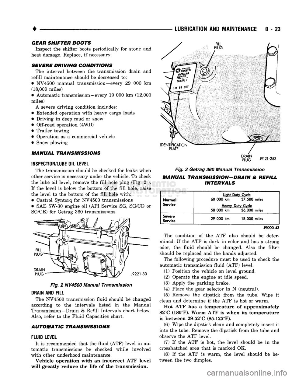
The transmission should be checked for leaks when
other service is necessary under the vehicle. To check
the lube oil level, remove the fill hole plug (Fig. 2 ). If the level is below the bottom of the fill hole, raise
the level to the bottom of the fill hole with:
• Castrol Syntorq for NV4500 transmissions
• SAE 5W-30 engine oil (API Service SG, SG/CD or
SG/CE) for Getrag 360 transmissions.
Fig.
2 NV4500 Manual
Transmission
DRAIN
AND
FILL
The NV4500 transmission fluid should be changed
according to the intervals listed in the Manual
Transmission—Drain & Refill Intervals chart below.
Also,
refer to the Fluid Capacities chart.
AUTOMATIC TRANSMISSIONS
FLUID
LEWEL
It is recommended that the fluid (ATF) level in au
tomatic transmissions be checked while involved
with other underhood maintenance.
Vehicle operation with an incorrect ATF level
will greatly reduce the life of the transmission.
Fig.
3 Getrag 360 Manual
Transmission
MANUAL TRANSMISSION-DRAIN & REFILL INTERVALS
Normal
Service
Light
Duty
Cycle
60 000
km
37,500
miles
Heavy
Duty
Cycle
58 000
km
36,000
miles
Severe
Service
29 000
km
18,000
miles
J9000-43
The condition of the ATF also should be deter
mined. If the ATF is dark in color and has a strong odor, the fluid should be changed. Also the filter should be replaced and the bands adjusted.
The following procedure must be used to check the
automatic transmission fluid (ATF) level.
(1) Position the vehicle on level ground.
(2) Operate the engine at idle speed.
(3) Apply the parking brake.
(4) Place the gear selector in N (neutral).
(5) Remove the dipstick from the tube. Wipe it
clean and determine if the ATF is hot or warm.
Hot ATF has a temperature of approximately
82°C (180°F). Warm ATF is when its temperature
is between 29-52°C (85-125°F). (6) Wipe the dipstick clean and completely insert it
into the tube. Remove the dipstick from the tube and
observe the ATF level.
(7) If the ATF is hot, the level should be in the
crosshatched area that is marked OK.
(8) If the ATF is warm, the level should be be
tween the two dimples.
Page 43 of 1502
0
- 24
LUBRICATION
AND
MAINTENANCE
•
CAUTION:
Do not
overfill
the
transmission.
(9) Adjust
the
level
of the ATF
accordingly.
It
is
important
to use the
correct fluid
in an
automatic transmission. MOPAR®ATF PLUS
(ATF Type
7176)
should
be
used. Dexron®
II
ATF
can be
used
if the
recommended fluid
is not
available,
(10) Insert
the
dipstick into
the
tube.
DRAIN, FILTER CHANGE, BAND ADJUSTMENT AND REFILL
The chart below lists
the
intervals
at
which
the
transmission should
be
serviced. Also, refer
to the
Fluid Capacities chart
for
fill capacity.
AUTOMATIC TRANSMISSION SERVICE
IN-
TERVALS
Normal
Usage
Light
Duty
Cycle
60 000
km
37,500
miles
Heavy
Duty
Cycle
38
000 km 24,000
miles
Severe
Usage
19 000 km 12,000
miles
J9100-19
It
is
very important
to use the
correct fluid
in
an automatic transmission. MOPAR®ATF PLUS
(ATF Type
7176)
should
be
used.
An
equivalent
Dexron®
II ATF
could
be
used only
if the
recom
mended fluid
is not
available.
The torque converter does
not
have
a
drain plug.
No attempt should
be
made
to
drain
the
converter.
Refer
to
Group
21
—Transmissions
for
transmission
drain
and
refill procedures.
TRANSFER
CASE
(4WD
VEHICLES)
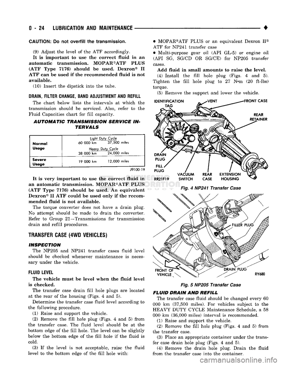
INSPECTION The NP205
and
NP241 transfer cases fluid level
should
be
checked whenever maintenance
is
neces
sary under
the
vehicle.
FLUID
LEVEL
The vehicle must
be
level when
the
fluid level
is checked.
The transfer case drain fill hole plugs
are
located
at
the
rear
of the
housing (Figs.
4 and 5).
Determine
the
transfer case fluid level according
to
the following procedure.
(1) Raise
and
support
the
vehicle.
(2) Remove
the
fill hole plug (Figs.
4 and 5)
from
the transfer case.
The
fluid level should
be at the
bottom edge
of the
fill hole.
The
level
can be
slightly
below
the
bottom edge
of the
fill hole
if the
fluid
is
cold.
(3)
If the
level
is not
acceptable, raise
the
fluid
level
to the
bottom edge
of the
fill hole with: • MOPAR®ATF PLUS
or an
equivalent Dexron
II®
ATF
for
NP241 transfer case
• Multi-purpose gear
oil (API GL-5) or
engine
oil
(API
SG,
SG/CD
OR
SG/CE)
for
NP205 transfer
cases.
Add fluid
in
small amounts
to
raise
the
level. (4) Install
the
fill hole plug (Figs.
4 and 5).
Tighten
the
fill hole plug
to 27 N-m (20
ft-lbs) torque.
(5) Remove
the
support
and
lower
the
vehicle.
Fig.
4
HP241 Transfer
Case
Fig.
5
NP205 Transfer
Case
FLUID DRAIN
AND
REFILL The transfer case fluid should
be
changed every
60
000
km
(37,500 miles).
For
vehicles subject
to the
HEAVY DUTY CYCLE Maintenance Schedule,
a 58
000
km
(36,000 miles) interval
is
recommended.
(1) Raise
and
support
the
vehicle.
(2) Remove
the
fill hole plug (Figs.
4 and 5)
from
the transfer case. (3) Place
an
appropriate container under
the
trans
fer case drain hole plug (Figs.
4 and 5).
(4) Remove
the
drain hole plug. Drain
the
fluid
from
the
transfer case into
the
container.
Page 44 of 1502
•
LUBRICATION
AND
MAINTENANCE
0 - 25
CAUTION:
Do not
over-tighten
the
drain
and fill
hole
plugs.
Over-tightening
can strip the
hole
threads
and/or crack
the
aluminum housing.
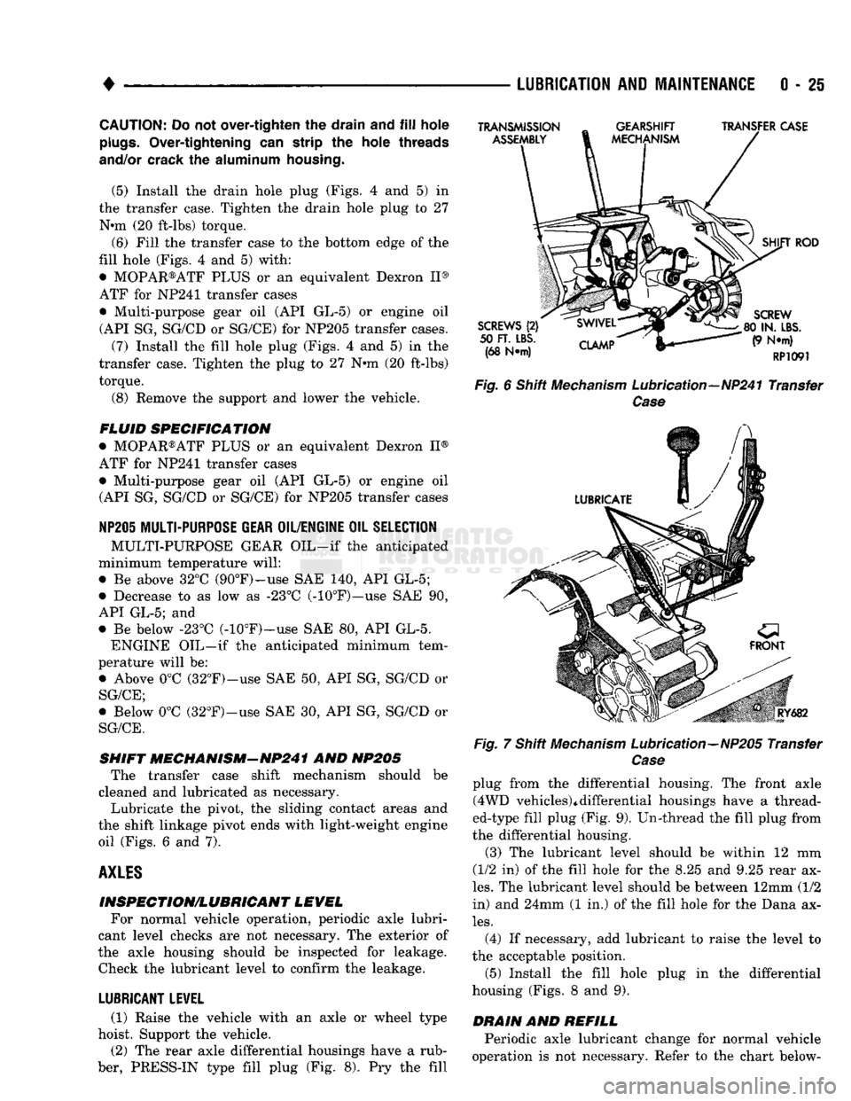
(5) Install the drain hole plug (Figs. 4 and 5) in
the transfer case. Tighten the drain hole plug to 27 N*m (20 ft-lbs) torque. (6) Fill the transfer case to the bottom edge of the
fill hole (Figs. 4 and 5) with: • MOPAR®ATF PLUS or an equivalent Dexron II®
ATF for NP241 transfer cases
• Multi-purpose gear oil (API GL-5) or engine oil (API SG, SG/CD or SG/CE) for NP205 transfer cases. (7) Install the fill hole plug (Figs. 4 and 5) in the
transfer case. Tighten the plug to 27 N«m (20 ft-lbs) torque.
(8) Remove the support and lower the vehicle.
FLUID SPECIFICATION
• MOPAR®ATF PLUS or an equivalent Dexron II®
ATF for NP241 transfer cases • Multi-purpose gear oil (API GL-5) or engine oil (API SG, SG/CD or SG/CE) for NP205 transfer cases
NP20I
MULTI-PURPOSE GEAR OIL/ENGINE
OIL
SELECTION
MULTI-PURPOSE GEAR OIL-if the anticipated
minimum temperature will: • Be above 32°C (90°F)-use SAE 140, API GL-5;
• Decrease to as low as -23°C (-10°F)-use SAE 90,
API GL-5; and • Be below -23°C (-10°F)-use SAE 80, API GL-5. ENGINE OIL—if the anticipated minimum tem
perature will be: ® Above 0°C (32°F)-use SAE 50, API SG, SG/CD or
SG/CE;
• Below 0°C (32°F)-use SAE 30, API SG, SG/CD or SG/CE.
SHIFT MECHANISM-NP241 AND NP205 The transfer case shift mechanism should be
cleaned and lubricated as necessary.
Lubricate the pivot, the sliding contact areas and
the shift linkage pivot ends with light-weight engine oil (Figs. 6 and 7).
AXLES
INSPECTION/LUBRICANT LEVEL For normal vehicle operation, periodic axle lubri
cant level checks are not necessary. The exterior of
the axle housing should be inspected for leakage. Check the lubricant level to confirm the leakage.
LUBRICANT LEVEL
(1) Raise the vehicle with an axle or wheel type
hoist. Support the vehicle.
(2) The rear axle differential housings have a rub
ber, PRESS-IN type fill plug (Fig. 8). Pry the fill
TRANSMISSION
ASSEMBLY
GEARSHIFT
MECHANISM TRANSFER CASE
SCREWS
(2)
50
FT. LBS.
(68 N*m)
CLAMP
SHIFT
ROD
SCREW
80 IN.
LBS.
(9 N*m)
RP1091
Fig.
6 Shift
Mechanism
Lubrication—NP241 Transfer
Case
Fig.
RY682
7 Shift
Mechanism
Lubrication—NP205 Transfer
Case
plug from the differential housing. The front axle (4WD vehicles)*differential housings have a thread
ed-type fill plug (Fig. 9). Un-thread the fill plug from
the differential housing.
(3) The lubricant level should be within 12 mm
(1/2 in) of the fill hole for the 8.25 and 9.25 rear ax
les.
The lubricant level should be between 12mm (1/2
in) and 24mm (1 in.) of the fill hole for the Dana ax
les.
(4) If necessary, add lubricant to raise the level to
the acceptable position.
(5) Install the fill hole plug in the differential
housing (Figs. 8 and 9).
DRAIN
AND
REFILL
Periodic axle lubricant change for normal vehicle
operation is not necessary. Refer to the chart below-
Page 46 of 1502
•
LUBRICATION
AND
MAINTENANCE
0 - 27 (3) Continue lubricating until it appears at the
pressure relief hole in the expansion plug located at the slip-yoke end.
(4) Cover the pressure relief hole with a finger.
Continue to force lubricant into the fitting until it
appears at the slip-yoke seal.
U-JOINT
INSPECTION
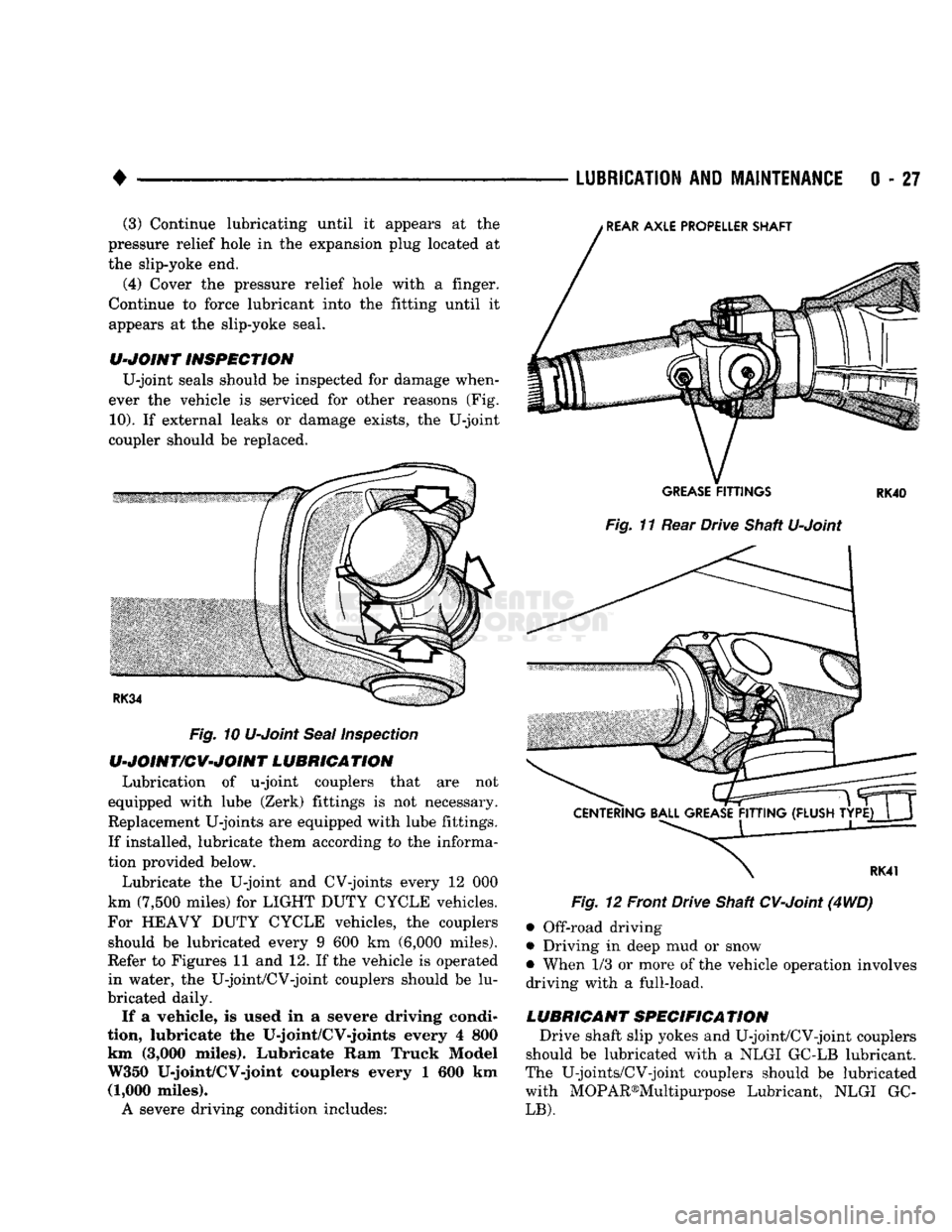
U-joint seals should be inspected for damage when
ever the vehicle is serviced for other reasons (Fig.
10).
If external leaks or damage exists, the U-joint
coupler should be replaced.
Fig.
10 U-Joint
Seal
Inspection
U-JOINT/CV-JOINT
LUBRICATION
Lubrication of u-joint couplers that are not
equipped with lube (Zerk) fittings is not necessary.
Replacement U-joints are equipped with lube fittings.
If installed, lubricate them according to the informa tion provided below.
Lubricate the U-joint and CV-joints every 12 000
km (7,500 miles) for LIGHT DUTY CYCLE vehicles.
For HEAVY DUTY CYCLE vehicles, the couplers should be lubricated every 9 600 km (6,000 miles).
Refer to Figures 11 and 12. If the vehicle is operated
in water, the U-joint/CV-joint couplers should be lu
bricated daily. If a vehicle, is used in a severe driving condi
tion,
lubricate the U-joint/CV-joints every 4 800
km (3,000 miles). Lubricate Ram Truck Model W350 U-joint/CV-joint couplers every 1 600 km
(1,000 miles). A severe driving condition includes:
GREASE
FITTINGS
RK40
Fig.
11 Rear Drive Shaft U-Joint
Fig.
12 Front Drive Shaft
CV-Joint
(4WD)
• Off-road driving
• Driving in deep mud or snow
• When 1/3 or more of the vehicle operation involves
driving with a full-load.
LUBRICANT
SPECIFICATION
Drive shaft slip yokes and U-joint/CV-joint couplers
should be lubricated with a NLGI GC-LB lubricant.
The U-joints/CV-joint couplers should be lubricated with MOPAR®Multipurpose Lubricant, NLGI GC-
LB).