1993 DODGE TRUCK fuel tank capacity
[x] Cancel search: fuel tank capacityPage 652 of 1502
5.2L
ENGINE
9 - 47
S.2L ENGINE
SERVICE
PROCEDURES
INDEX
page
Camshaft
. , . 61
Crankshaft
68
Crankshaft Main Bearings
69
Crankshaft Rear
Oil
Seals
...... ........
70
Cylinder Block ...........................
71
Cylinder Head Cover
. . . . 51
Cylinder Heads
52
Distributor
62
Engine
Assembly
. 50
Engine
Front Mounts
47
Engine
Rear Mount ...............
48
Front Crankshaft
Oil
Seal Replacement
. . 61
GENERAL
INFORMATION
The 5.2 Liter (318 CID) eight-cylinder engine is a
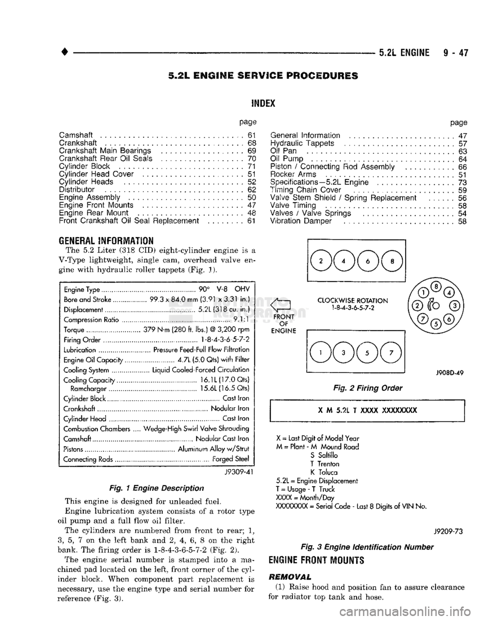
V-Type lightweight, single cam, overhead valve en gine with hydraulic roller tappets (Fig. J).
Engine
Type ....
90° V-8 OHV
Bore
and Stroke .....
99.3
x
84.0 mm
(3.91
x
3.31
in.)
Displacement................
5.2L(318cu.
in.)
Compression
Ratio ....... .
9.1:1
Torque .. 379 N-m (280
ft.
lbs.)
@
3,200
rpm
Firing Order .... 1-8-4-3-6-5-7-2
Lubrication
.......
Pressure
Feed-Full Flow
Filtration
Engine
Oil
Capacity......
4.7L
(5.0 Qts)
with Filter
Cooling System ...... Liquid Cooled-Forced
Circulation
Cooling Capacity..........
16.1L(17.0Qts)
Ramcharger
15.6L
(16.5 Qts)
Cylinder Block
,
Cast
Iron
Crankshaft Nodular Iron
Cylinder Head ..............
Cast
Iron
Combustion Chambers
..
Wedge-High
Swirl Valve Shrouding
Camshaft Nodular Cast Iron
Pistons
Aluminum Alloy
w/Strut
Connecting
Rods...........
Forged
Steel
J9309-41
Fig. 1
Engine
Description
This engine is designed for unleaded fuel.
Engine lubrication system consists of a rotor type
oil pump and a full flow oil filter.
The cylinders are numbered from front to rear; 1?
3,
5, 7 on the left bank and 2, 4, 6, 8 on the right
bank. The firing order is 1-8-4-3-6-5-7-2 (Fig. 2).
The engine serial number is stamped into a ma
chined pad located on the left, front corner of the cyl
inder block. When component part replacement is
necessary, use the engine type and serial number for
reference (Fig. 3).
page
General
Information
.......................
47
Hydraulic Tappets
57
Oil
Pan . 63
Oil Pump
. 64
Piston
/
Connecting
Rod
Assembly
66
Rocker
Arms
51
Specifications—5.2L Engine
73
Timing Chain Cover ................
59
Valve Stem Shield
/
Spring Replacement
56
Valve Timing
. 58
Valves
/
Valve Springs
54
Vibration
Damper
. . 58
J908D-49
Fig.
2 Firing Order
X
M 5.2L T
XXXX
XXXXXXXX
X
~
Last Digit of
Model
Year
M
=
Plant
- M
Mound
Road
S
Saltillo
T
Trenton
K
Toluca
5.2L
=
Engine Displacement
T
=
Usage
-
T Truck
XXXX
=
Month/Day
XXXXXXXX
=
Serial Code
-
Last
8
Digits
of
VIN
No.
J9209-73
Fig.
3
Engine
Identification
Number
ENGINE
FRONT
MOUNTS
REMOVAL
(1) Raise hood and position fan to assure clearance
for radiator top tank and hose.
Page 682 of 1502
5.9L
ENGINE SERVICE PROCEDURES
INDEX
page
Camshaft
91
Crankshaft
98
Crankshaft Main Bearings
99
Crankshaft Rear
Oil
Seals
100
Cylinder
Block
101
Cylinder
Head Cover
81
Cylinder
Heads
82
Distributor
92
Engine Assembly
80
Engine
Front
Mounts
77
Engine Rear Mount
78
Front
Crankshaft
Oil
Seal Replacement
91
page
General
Information
77
Hydraulic
Tappets
87
Oil
Pan 93
Oil Pump
. 94
Piston
/
Connecting
Rod
Assembly
96
Rocker Arms
81
Specifications—5.9L
Engine
103
Timing
Chain Cover
89
Valve Stem Shield
/
Spring Replacement
86
Valve
Timing
. 88
Valves
/
Valve Springs
84
Vibration
Damper
88
GENERAL
INFORMATION
The 5.9 Liter (360 CID) eight-cylinder engine is a
V-Type lightweight, single cam, overhead valve en
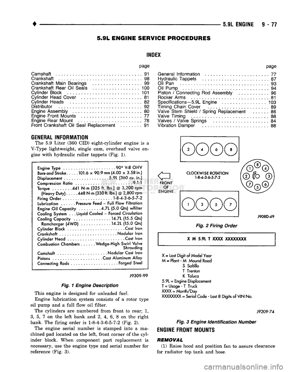
gine with hydraulic roller tappets (Fig. 1).
Engine Type .90° V-8 OHV
Bore and Stroke 101.6 x 90.9
mm
(4.00 x 3.58 in.)
Displacement 5.9L (360 cu. in.)
Compression Ratio 9.1:1
Torque 441 N-m (325 ft. lbs.) @ 3,200 rpm (Heavy Duty). 448 N-m (330 ft. lbs.)
@
2,800 rpm
Firing Order
1-8-4-3-6-5-7-2
Lubrication ...... Pressure Feed - Full Flow Filtration
Engine Oil Capacity .4.7L (5.0 Qts) w/filter
Cooling System . .
.
Liquid Cooled - Forced Circulation Cooling Capacity ..... . . 14.7L (15.5 Qts)
Ramcharger (4WD) 14.2L (15.0 Qts)
Cylinder Block Cast Iron Crankshaft
-
Nodular Iron
Cylinder Head • . Cast Iron Combustion Chambers Wedge-High Swirl Valve
Shrouding
Camshaft Nodular Cast Iron Pistons Cast Aluminum Alloy
Connecting Rods Forged Steel
J9309-99
Fig. 1
Engine
Description
This engine is designed for unleaded fuel.
Engine lubrication system consists of a rotor type
oil pump and a full flow oil filter.
The cylinders are numbered from front to rear; 1,
3,
5, 7 on the left bank and 2, 4, 6, 8 on the right
bank. The firing order is
1-8-4-3-6-5-7-2
(Fig. 2).
The engine serial number is stamped into a ma
chined pad located on the left, front corner of the cyl
inder block. When component part replacement is
necessary, use the engine type and serial number for
reference (Fig. 3).
o
FRONT OF
ENGINE CLOCKWISE ROTATION
1-8-4-3-6-5-7-2
J908D-49
Fig. 2 Firing Order
X
M 5.9L T
XXXX
XXXXXXXX
X
= Last Digit of Model Year
M = Plant - M Mound Road S Saltillo
T Trenton K Toluca
5.9L = Engine Displacement
T
= Usage -
T
Truck
XXXX
= Month/Day
XXXXXXXX
= Serial Code - Last 8 Digits of
VIN
No.
J9209-74
Fig.
3
Engine
identification
Number
ENGINE
FRONT MOUNTS
REMOVAL (1) Raise hood and position fan to assure clearance
for radiator top tank and hose.
Page 712 of 1502
•
5.9L
(DIESEL)
ENGINE
9 -
107
5.9L
(DIESEL)
ENGINE
SERVICE
PROCEDURES
INDEX
page
Camshaft
127
Crankshaft
138
Cylinder
Block
129
Cylinder
Head
113
Engine
Assembly
. 109
Engine
Front
Mounts
(Insulators
/
Brackets)
... 107
Engine
Rear Support
108
Gear
Housing
/
Cover
122
General
Information
107
Oil Cooler Element
/
Gasket
. 149
Oil
Filter
148
page
Oil
Filter
Bypass
Valve
. 148
Oil Pan
/
Suction Tube
146
Oil Pressure Regulator Valve
/
Spring
148
Oil Pump
146
Piston
/
Connecting
Rod
Assembly
134
Rocker
Levers
/
Push
Rods
112
Specifications—5.9L Diesel Engines
151
Tappet
125
Timing
Pin
123
Valve Clearance
Adjustment
...............
121
Valves
and
Valve Springs
116
GENERAL INFORMATION The
5.9
Liter
(359 CID)
six-cylinder diesel engine
is
an
In-line valve-in head type
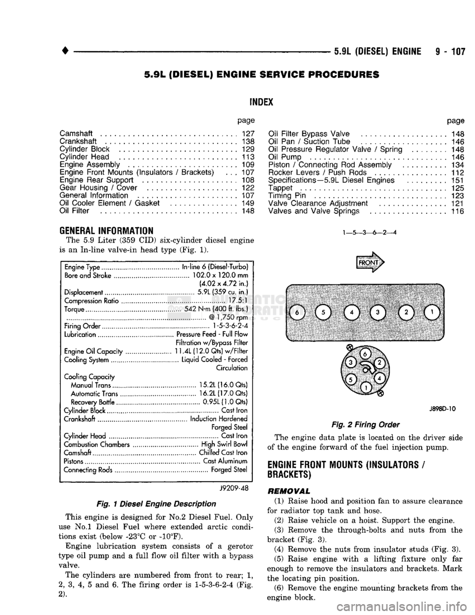
(Fig. 1).
Fig.
1
Diesel
Engine
Description
This engine
is
designed
for No.2
Diesel Fuel. Only
use
No.l
Diesel Fuel where extended arctic condi
tions exist (below -23°C
or -10°F).
Engine lubrication system consists
of a
gerotor
type
oil
pump
and a
full flow
oil
filter with
a
bypass valve.
The cylinders
are
numbered from front
to
rear;
1,
2,
3, 4, 5 and 6. The
firing order
is
1-5-3-6-2-4
(Fig.
2).
J898D-10
Fig.
2
Firing Order
The engine data plate
is
located
on the
driver side
of
the
engine forward
of the
fuel injection pump.
ENGINE FRONT MOUNTS (INSULATORS
/
BRACKETS)
REMOVAL (1) Raise hood
and
position
fan to
assure clearance
for radiator
top
tank
and
hose.
(2) Raise vehicle
on a
hoist. Support
the
engine.
(3) Remove
the
through-bolts
and
nuts from
the
bracket
(Fig. 3).
(4) Remove
the
nuts from insulator studs
(Fig. 3).
(5) Raise engine with
a
lifting fixture only
far
enough
to
remove
the
insulators
and
brackets. Mark
the locating
pin
position.
(6) Remove
the
engine mounting brackets from
the
engine block.
Engine Type
In-line
6
(Diesel-Turbo)
Bore and Stroke 102.0 x 120.0 mm
(4.02x4.72 in.)
Displacement 5.9L (359 cu.
in.)
Compression Ratio 17.5:1
Torque 542 N-m (400 ft. lbs.)
@
1,750 rpm
Firing Order
1-5-3-6-2-4
Lubrication Pressure Feed - Full Flow
Filtration w/Bypass Filter
Engine Oil Capacity
11.4L
(12.0 Qts) w/Filter
Cooling System Liquid Cooled
-
Forced
Circulation
Cooling Capacity
Manual Trans 15.2L (16.0 Qts)
Automatic Trans 16.2L (17.0 Qts)
Recovery Bottle 0.95L(1.0Qts)
Cylinder Block.... Cast Iron
Crankshaft Induction Hardened
Forged Steel
Cylinder Head Cast Iron
Combustion Chambers High Swirl Bowl
Camshaft.... Chilled Cast Iron
Pistons Cast Aluminum
Connecting Rods Forged Steel
J9209-48
Page 822 of 1502
•
FUEL SYSTEM
14 • 3
FUEL
DELIVERY SYSTEM-EXCEPT DIESEL
INDEX
page
Fuel Filter—3.9L/5.2L Gas Engine
............
10
Fuel
Filter—5.9L
Gas Engine
11
Fuel Pressure Leak Down Test—3.9L/5.2L Engine
. 8
Fuel Pressure Leak Down Test—5.9L Engine
.... 9
Fuel Pump Capacity
Test—All
Gas
Engines
..... 8
Fuel Pump
Control
........................
5
Fuel Pump Module—3.9L/5.2L Engines
3
GENERAL INFORMATION
Two different types
of
fuel delivery/fuel return sys
tems
are
used.
The
system used with
the
3.9L/5.2L
engine will route excess fuel pressure back
to the
fuel tank through
a
fuel return line.
The
system used
with
the 5.9L
engine will
not
have
a
separate fuel
re
turn line. This system will
be
referred
to as a re-
turnless type.
The
fuel pump module used with
the
5.9L engine will contain
a
combination fuel pressure
regulator
and
fuel filter. Refer
to the
following Fuel
Pump Module
for
additional information
or,
refer
to
the Multi-Port Fuel Injection sections
of
this Fuel System group. A separate frame mounted fuel filter will
not be
used with
any 5.9L gas
powered engine.
FUEL
PUMP
M0DULE-3.9L/5.2L
ENGINES
The fuel pump module
on
vehicles equipped with
3.9L/5.2L engines
is
installed
in the top of the
fuel
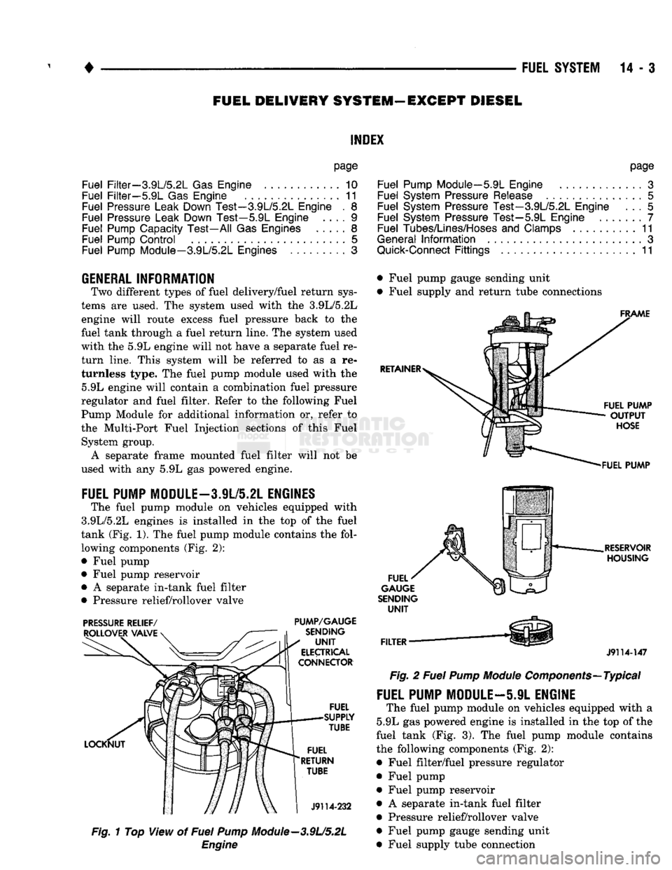
tank (Fig.
1). The
fuel pump module contains
the
fol lowing components (Fig.
2):
• Fuel pump
• Fuel pump reservoir
•
A
separate in-tank fuel filter
• Pressure relief/rollover valve
PRESSURE
RELIEF/
PUMP/GAUGE
Fig.
1
Top View
of
Fuel
Pump
Module—3.9U5.2L
Engine
page
Fuel Pump Module—5.9L Engine
.............
3
Fuel System Pressure Release
...............
5
Fuel System Pressure Test—3.9L/5.2L Engine
... 5
Fuel System Pressure Test—5.9L Engine
7
Fuel Tubes/Lines/Hoses
and
Clamps
..........
11
General
Information
3
Quick-Connect
Fittings
11
• Fuel pump gauge sending unit
• Fuel supply
and
return tube connections
J9114-147
Fig.
2
Fuel
Pump
Module
Components—Typical
FUEL PUMP MODULE—5.9L ENGINE
The fuel pump module
on
vehicles equipped with
a
5.9L
gas
powered engine
is
installed
in the top of
the
fuel tank
(Fig. 3). The
fuel pump module contains
the following components (Fig.
2):
• Fuel filter/fuel pressure regulator
• Fuel pump • Fuel pump reservoir
•
A
separate in-tank fuel filter
• Pressure relief/rollover valve
• Fuel pump gauge sending unit
• Fuel supply tube connection
Page 826 of 1502
•
FUEL
SYSTEM
14 - 7
Fig.
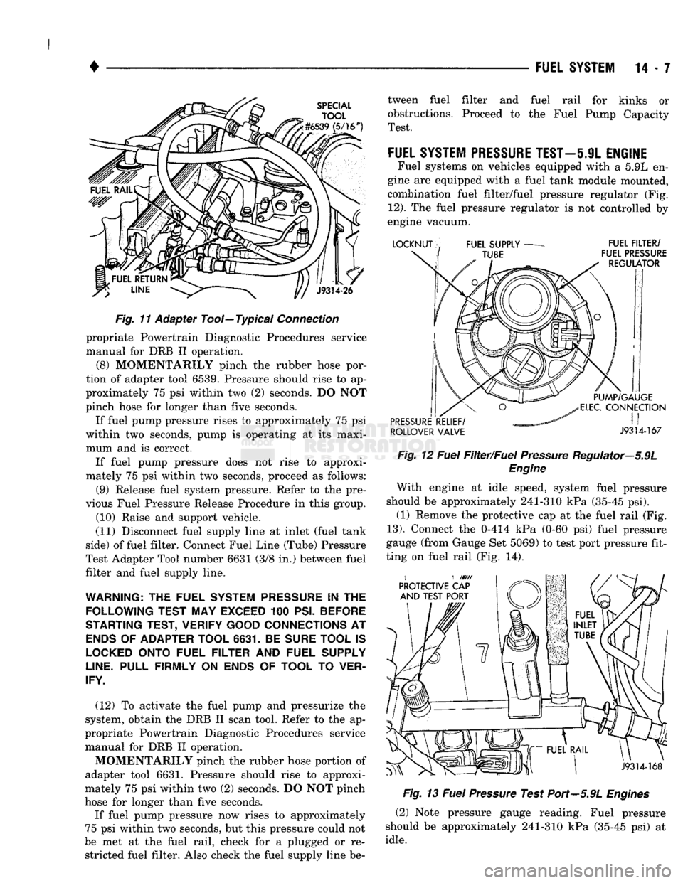
1"f
Adapter Tool—Typical
Connection
propriate Powertrain Diagnostic Procedures service
manual for DRB II operation.
(8) MOMENTARILY pinch the rubber hose por
tion of adapter tool 6539. Pressure should rise to ap
proximately 75 psi within two (2) seconds. DO NOT
pinch hose for longer than five seconds.
If fuel pump pressure rises to approximately 75 psi
within two seconds, pump is operating at its maxi mum and is correct. If fuel pump pressure does not rise to approxi
mately 75 psi within two seconds, proceed as follows:
(9) Release fuel system pressure. Refer to the pre
vious Fuel Pressure Release Procedure in this group. (10) Raise and support vehicle.
(11) Disconnect fuel supply line at inlet (fuel tank
side) of fuel filter. Connect Fuel Line (Tube) Pressure
Test Adapter Tool number 6631 (3/8 in.) between fuel
filter and fuel supply line.
WARNING:
THE
FUEL SYSTEM
PRESSURE
IN THE
FOLLOWING TEST MAY EXCEED
100
PSI. BEFORE
STARTING TEST, VERIFY GOOD CONNECTIONS
AT
ENDS
OF
ADAPTER TOOL 6631.
BE
SURE TOOL
IS
LOCKED
ONTO FUEL FILTER
AND
FUEL SUPPLY
LINE.
PULL FIRMLY
ON
ENDS
OF
TOOL
TO
VER
IFY.
(12) To activate the fuel pump and pressurize the
system, obtain the DRB II scan tool. Refer to the ap
propriate Powertrain Diagnostic Procedures service manual for DRB II operation.
MOMENTARILY pinch the rubber hose portion of
adapter tool 6631. Pressure should rise to approxi
mately 75 psi within two (2) seconds. DO NOT pinch
hose for longer than five seconds.
If fuel pump pressure now rises to approximately
75 psi within two seconds, but this pressure could not
be met at the fuel rail, check for a plugged or re stricted fuel filter. Also check the fuel supply line be tween fuel filter and fuel rail for kinks or
obstructions. Proceed to the Fuel Pump Capacity
Test.
FUEL
SYSTEM PRESSURE
TEST—5.9L
ENGINE
Fuel systems on vehicles equipped with a 5.9L en
gine are equipped with a fuel tank module mounted,
combination fuel filter/fuel pressure regulator (Fig.
12).
The fuel pressure regulator is not controlled by
engine vacuum.
ROLLOVER VALVE J9314-167 Fig.
12
Fuel
Filter/Fuel
Pressure
Regulator—5.9L
Engine
With engine at idle speed, system fuel pressure
should be approximately 241-310 kPa (35-45 psi). (1) Remove the protective cap at the fuel rail (Fig.
13).
Connect the 0-414 kPa (0-60 psi) fuel pressure
gauge (from Gauge Set 5069) to test port pressure fit
ting on fuel rail (Fig. 14).
Fig.
13
Fuel
Pressure
Test Port—5.9L
Engines
(2) Note pressure gauge reading. Fuel pressure
should be approximately 241-310 kPa (35-45 psi) at
idle.
Page 827 of 1502
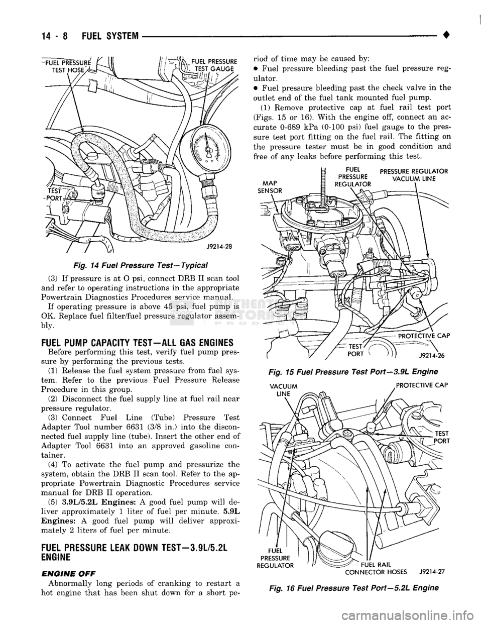
Fig.
14
Fuel
Pressure
Test—Typical
(3) If pressure is at O psi, connect DRB II scan tool
and refer to operating instructions in the appropriate
Powertrain Diagnostics Procedures service manual. If operating pressure is above 45 psi, fuel pump is
OK. Replace fuel filter/fuel pressure regulator assem-
bly.
FUEL
PUMP CAPACITY TEST-ALL GAS ENGINES
Before performing this test, verify fuel pump pres
sure by performing the previous tests. (1) Release the fuel system pressure from fuel sys
tem. Refer to the previous Fuel Pressure Release
Procedure in this group. (2) Disconnect the fuel supply line at fuel rail near
pressure regulator. (3) Connect Fuel Line (Tube) Pressure Test
Adapter Tool number 6631 (3/8 in.) into the discon nected fuel supply line (tube). Insert the other end of
Adapter Tool 6631 into an approved gasoline con
tainer.
(4)
To activate the fuel pump and pressurize the
system, obtain the DRB II scan tool. Refer to the ap
propriate Powertrain Diagnostic Procedures service manual for DRB II operation. (5) 3.9L/5.2L Engines: A good fuel pump will de
liver approximately 1 liter of fuel per minute. 5.9L
Engines: A good fuel pump will deliver approxi
mately 2 liters of fuel per minute.
FUEL
PRESSURE
LEAK DOWN
TEST-3
JL/5.2L
ENGINE
ENGINE
OFF Abnormally long periods of cranking to restart a
hot engine that has been shut down for a short pe riod of time may be caused by:
• Fuel pressure bleeding past the fuel pressure reg
ulator.
• Fuel pressure bleeding past the check valve in the
outlet end of the fuel tank mounted fuel pump. (1) Remove protective cap at fuel rail test port
(Figs.
15 or 16). With the engine off, connect an ac
curate 0-689 kPa (0-100 psi) fuel gauge to the pres
sure test port fitting on the fuel rail. The fitting on
the pressure tester must be in good condition and
free of any leaks before performing this test.
PRESSURE
REGULATOR
CONNECTOR
HOSES
J9214-27
Fig.
16
Fuel
Pressure
Test Port—5.2L
Engine
Page 912 of 1502
•
FUEL SYSTEM
14-93 There is a drain at the bottom of the separator fil
ter (Fig. 13). Place a drain pan under the drain tube. With the engine not running, hold the drain open
until all water and contaminants have been removed and clean fuel exits the drain. Dispose of mixture in
drain pan according to applicable regulations.
If excess water gathers in separator/filter in a short
time,
the fuel tank must be removed, drained and cleaned.
HIGH
PRESSURE FUEL LINE RESTRICTIONS
High pressure fuel line leaks can cause starting
problems, poor engine performance and engine miss under load. Restricted high pressure lines can cause starting problems, poor engine performance, engine
miss under load and black smoke from exhaust.
WARNING:
USE
EXTREME
CAUTION
WHEN
IN
SPECTING
FOR HIGH
PRESSURE
FUEL
LEAKS.
IN
SPECT
FOR HIGH
PRESSURE
FUEL
LEAKS
WITH
A
SHEET
OF
CARDBOARD.
HIGH
FUEL
INJECTION
PRESSURE
CAN
CAUSE
PERSONAL
INJURY
IF
CONTACT
IS
MADE
WITH
THE
SKIN.
Start the engine. Move the cardboard over the high
pressure fuel lines and check for fuel spray onto the cardboard. If a high pressure line connection is leak
ing, bleed the system and tighten the connection. Re
fer to the 5.9L Diesel Service Procedures section for air bleeding procedures. Replace damaged, restricted
or leaking high pressure fuel lines with the correct replacement line.
CAUTION:
The
high pressure
fuel
lines must
be
clamped securely
in
place
in the
holders.
The
lines cannot contact each other
or
other components.
Do
not
attempt
to
weld high pressure
fuel
lines
or to
repair lines
that
are
damaged. Only
use the
recom
mended lines when replacement
of
high pressure
fuel
line
is
necessary.
KSB
SOLENOID
The KSB solenoid will click when it is energized
and de-energized. If the solenoid does not click when 12 volts is sup
plied to it, replace the solenoid.
MECHANICAL
LIFT
PUMP
An improperly operating lift pump can cause low
engine power. Inspect the fuel supply line to the
pump for restrictions, kinks or leaks. Fuel leaking
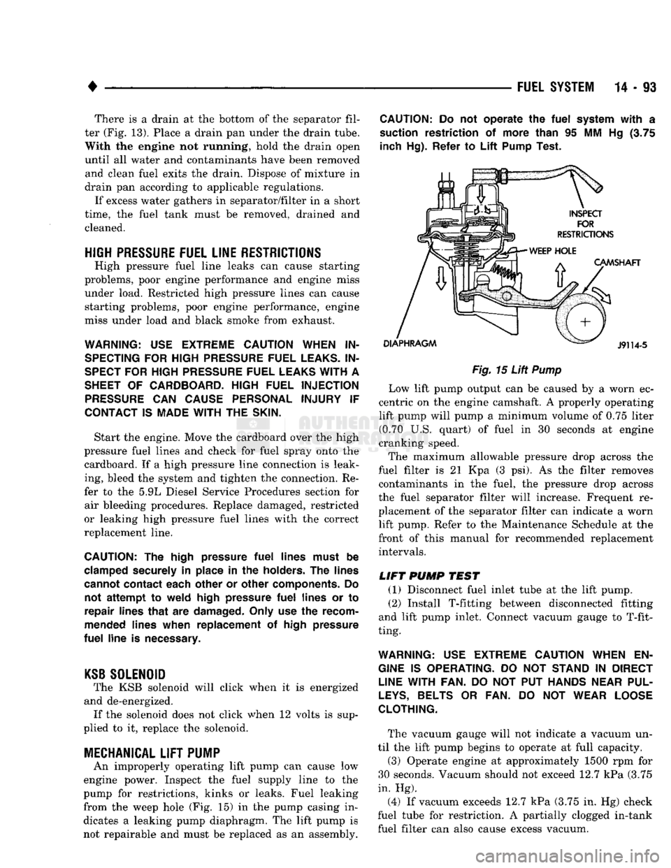
from the weep hole (Fig. 15) in the pump casing in
dicates a leaking pump diaphragm. The lift pump is not repairable and must be replaced as an assembly.
CAUTION:
Do not
operate
the
fuel
system
with
a
suction restriction
of
more than
95 MM Hg (3.75
inch Hg). Refer
to
Lift
Pump Test.
Fig.
15
Lift
Pump
Low lift pump output can be caused by a worn ec
centric on the engine camshaft. A properly operating lift pump will pump a minimum volume of 0.75 liter (0.70 U.S. quart) of fuel in 30 seconds at engine
cranking speed.
The maximum allowable pressure drop across the
fuel filter is 21 Kpa (3 psi). As the filter removes contaminants in the fuel, the pressure drop across
the fuel separator filter will increase. Frequent re
placement of the separator filter can indicate a worn lift pump. Refer to the Maintenance Schedule at the
front of this manual for recommended replacement intervals.
LIFT
PUMP
TEST
(1) Disconnect fuel inlet tube at the lift pump. (2) Install T-fitting between disconnected fitting
and lift pump inlet. Connect vacuum gauge to T-fit
ting.
WARNING:
USE
EXTREME
CAUTION
WHEN
EN
GINE
IS
OPERATING.
DO NOT
STAND
IN
DIRECT
LINE
WITH FAN.
DO NOT PUT
HANDS
NEAR
PUL
LEYS,
BELTS
OR FAN. DO NOT
WEAR
LOOSE
CLOTHING.
The vacuum gauge will not indicate a vacuum un
til the lift pump begins to operate at full capacity.
(3) Operate engine at approximately 1500 rpm for
30 seconds. Vacuum should not exceed 12.7 kPa (3.75
in. Hg).
(4) If vacuum exceeds 12.7 kPa (3.75 in. Hg) check
fuel tube for restriction. A partially clogged in-tank fuel filter can also cause excess vacuum.