1993 DODGE TRUCK remote control
[x] Cancel search: remote controlPage 410 of 1502
•
AUDIO
SYSTEMS
8F - 7
SERVICE
PROCEDURES
RADIO
REPLACEMENT
REMOVAL
(1) Disconnect negative cable from battery.
CAUTION:
Map
lamp
must
be
removed
to
prevent
damage
to instrument panel.
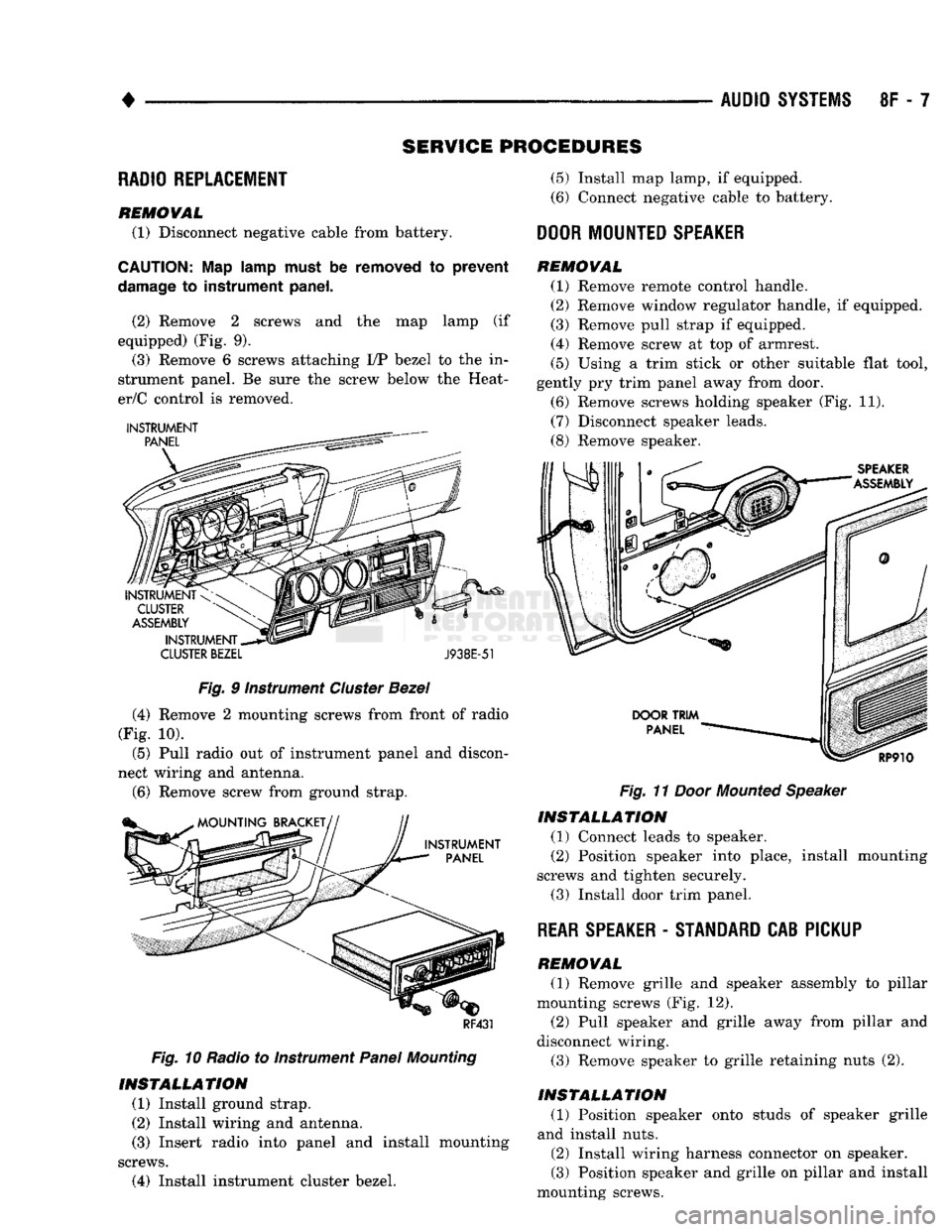
(2) Remove 2 screws and the map lamp (if
equipped) (Fig. 9). (3) Remove 6 screws attaching I/P bezel to the in
strument panel. Be sure the screw below the Heat-
er/C control is removed.
CLUSTER
BEZEL
J938E-51
Fig.
9 Instrument
Cluster
Bezel
(4) Remove 2 mounting screws from front of radio
(Fig. 10).
(5) Pull radio out of instrument panel and discon
nect wiring and antenna.
(6)
Remove screw from ground strap.
RF431
Fig.
10 Radio to Instrument
Panel
Mounting
INSTALLATION
(1) Install ground strap.
(2) Install wiring and antenna. (3) Insert radio into panel and install mounting
screws.
(4) Install instrument cluster bezel.
(5)
Install map lamp, if equipped.
(6) Connect negative cable to battery.
DOOR
MOUNTED
SPEAKER
REMOVAL
(1) Remove remote control handle.
(2) Remove window regulator handle, if equipped.
(3) Remove pull strap if equipped.
(4) Remove screw at top of armrest.
(5)
Using a trim stick or other suitable flat tool,
gently pry trim panel away from door.
(6) Remove screws holding speaker (Fig. 11).
(7) Disconnect speaker leads.
(8) Remove speaker.
Fig.
11
Door
Mounted
Speaker
INSTALLATION
(1) Connect leads to speaker.
(2) Position speaker into place, install mounting
screws and tighten securely.
(3) Install door trim panel.
REAR
SPEAKER
-
STANDARD
CAB PICKUP
REMOVAL
(1) Remove grille and speaker assembly to pillar
mounting screws (Fig. 12). (2) Pull speaker and grille away from pillar and
disconnect wiring.
(3) Remove speaker to grille retaining nuts (2).
INSTALLATION
(1) Position speaker onto studs of speaker grille
and install nuts.
(2) Install wiring harness connector on speaker.
(3) Position speaker and grille on pillar and install
mounting screws.
Page 461 of 1502
8P
- 2 POWER DOOR LOCKS
• SERVICE PROCEDURES
DOOR LOCK MOTOR REPLACEMENT
REMOVAL
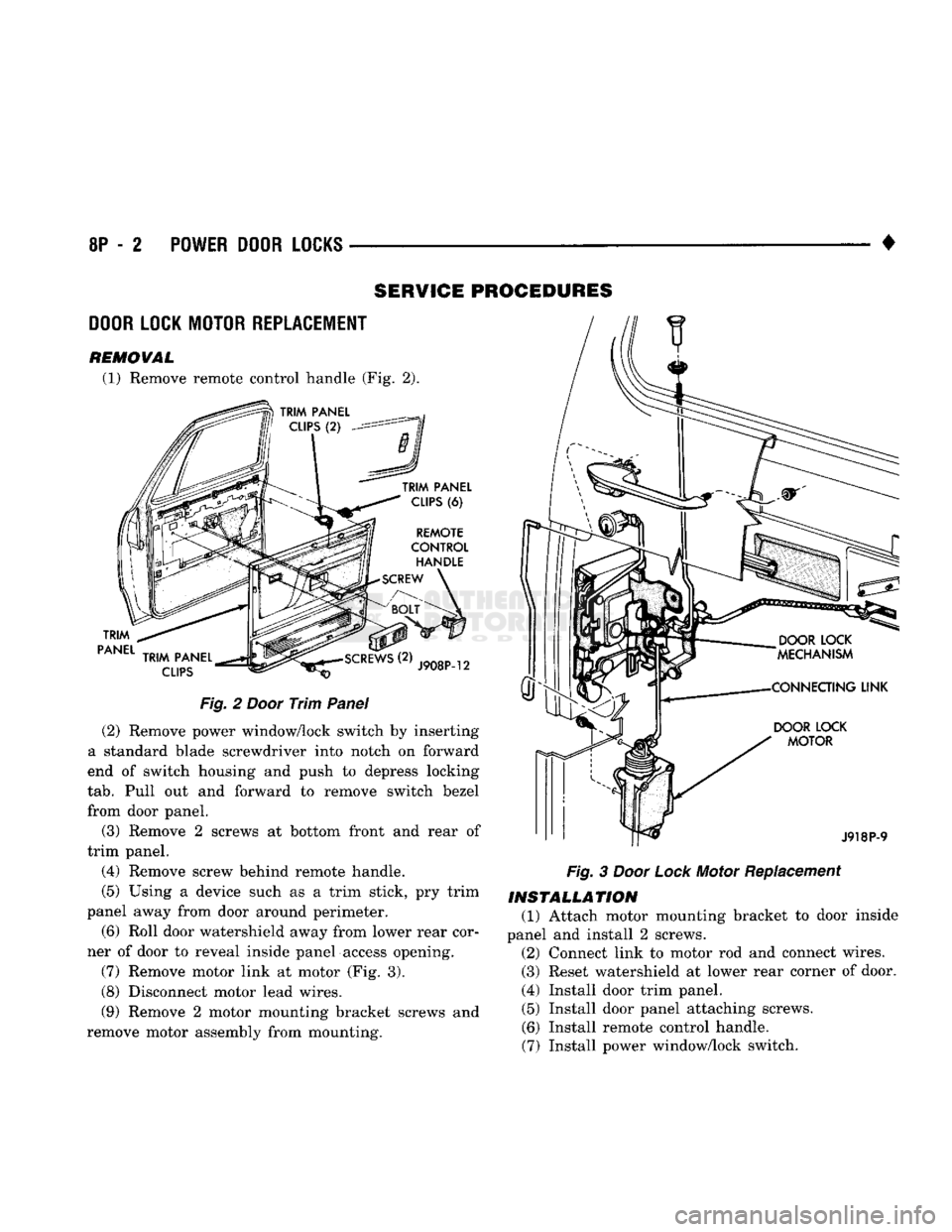
(1) Remove remote control handle (Fig. 2).
TRIM
PANEL
TRIM
PANEL
CLIPS
(6)
REMOTE
CONTROL
HANDLE
SCREW
TRIM
PANEL
CLIPS
J908P-12
Fig.
2
Door
Trim
Panel
(2) Remove power window/lock switch by inserting
a standard blade screwdriver into notch on forward
end of switch housing and push to depress locking
tab.
Pull out and forward to remove switch bezel
from door panel.
(3) Remove 2 screws at bottom front and rear of
trim panel.
(4) Remove screw behind remote handle.
(5) Using a device such as a trim stick, pry trim
panel away from door around perimeter.
(6) Roll door watershield away from lower rear cor
ner of door to reveal inside panel access opening.
(7) Remove motor link at motor (Fig. 3).
(8) Disconnect motor lead wires.
(9) Remove 2 motor mounting bracket screws and
remove motor assembly from mounting.
DOOR
LOCK
MOTOR
J918P-9
Fig.
3
Door
Lock
Motor Replacement
INSTALLATION
(1) Attach motor mounting bracket to door inside
panel and install 2 screws. (2) Connect link to motor rod and connect wires.
(3) Reset watershield at lower rear corner of door.
(4) Install door trim panel. (5) Install door panel attaching screws.
(6) Install remote control handle.
(7) Install power window/lock switch.
Page 464 of 1502
•
POWER
WINDOWS
8S - 3
FROM PIN
SIDE
OF
SWITCH
MASTER
WINDOW
LIFT
SWITCH
SWITCH
POSITION CONTINUITY
BETWEEN
OFF
PINS
1 & 2
PINS
2 & 3
PINS
2 &4
PINS
2 & 6
DRIVER'S
MP
PINS
3 & 5
PINS
2 & 6
PASSENGER'S
PINS
1 & 5
PINS
2 &4
DRIVER'S
PINS
5 & 6
PINS
2 & 3
TOWN
PASSENGER'S
PINS
1 & 2
PINS
4 & 5 898S-11
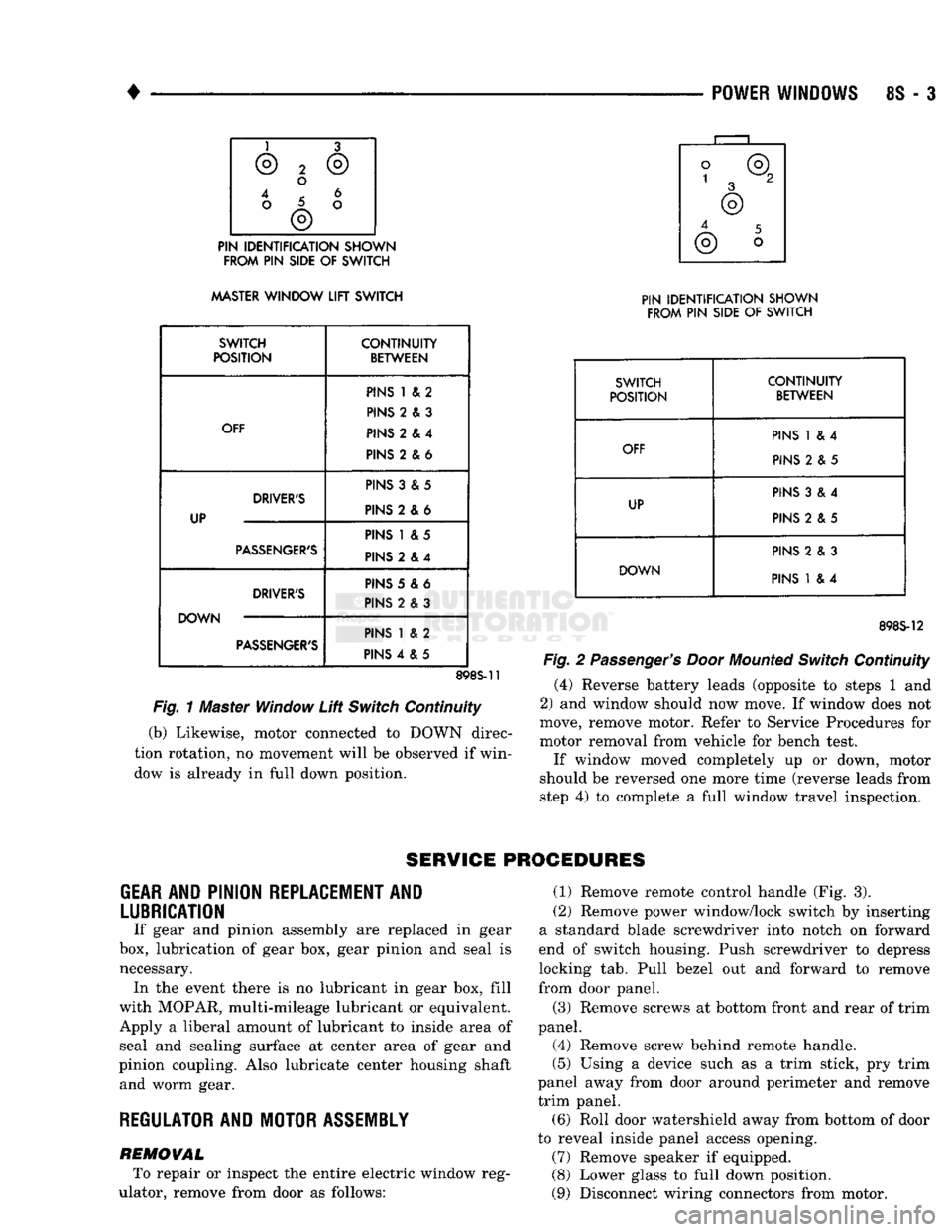
Fig.
1 Master Window
Lift
Switch
Continuity
(b) Likewise, motor connected to DOWN direc
tion rotation, no movement will be observed if win
dow is already in full down position.
PIN IDENTIFICATION SHOWN
FROM
PIN
SIDE
OF
SWITCH
SWITCH CONTINUITY
POSITION
BETWEEN
PINS
1 & 4
OFF
PINS
2 & 5
PINS
3 & 4
UP
PINS
2 & 5
PINS
2 & 3
DOWN
PINS
1 & 4
898S-12
Fig.
2
Passenger's Door
Mounted
Switch
Continuity
(4) Reverse battery leads (opposite to steps 1 and
2) and window should now move. If window does not
move, remove motor. Refer to Service Procedures for
motor removal from vehicle for bench test.
If window moved completely up or down, motor
should be reversed one more time (reverse leads from
step 4) to complete a full window travel inspection.
SERVICE
PROCEDURES
GEAR
AND PINION
REPLACEMENT
AND
LUBRICATION
If gear and pinion assembly are replaced in gear
box, lubrication of gear box, gear pinion and seal is necessary. In the event there is no lubricant in gear box, fill
with MOPAR, multi-mileage lubricant or equivalent. Apply a liberal amount of lubricant to inside area of seal and sealing surface at center area of gear and
pinion coupling. Also lubricate center housing shaft and worm gear.
REGULATOR
AND
MOTOR
ASSEMBLY
REMOVAL To repair or inspect the entire electric window reg
ulator, remove from door as follows: (1) Remove remote control handle (Fig. 3).
(2) Remove power window/lock switch by inserting
a standard blade screwdriver into notch on forward
end of switch housing. Push screwdriver to depress
locking tab. Pull bezel out and forward to remove
from door panel.
(3) Remove screws at bottom front and rear of trim
panel.
(4) Remove screw behind remote handle.
(5)
Using a device such as a trim stick, pry trim
panel away from door around perimeter and remove
trim panel. (6) Roll door watershield away from bottom of door
to reveal inside panel access opening. (7) Remove speaker if equipped.
(8) Lower glass to full down position.
(9) Disconnect wiring connectors from motor.
Page 468 of 1502
POWER
MIRRORS
CONTENTS
page
SERVICE PROCEDURES
2
GENERAL
INFORMATION
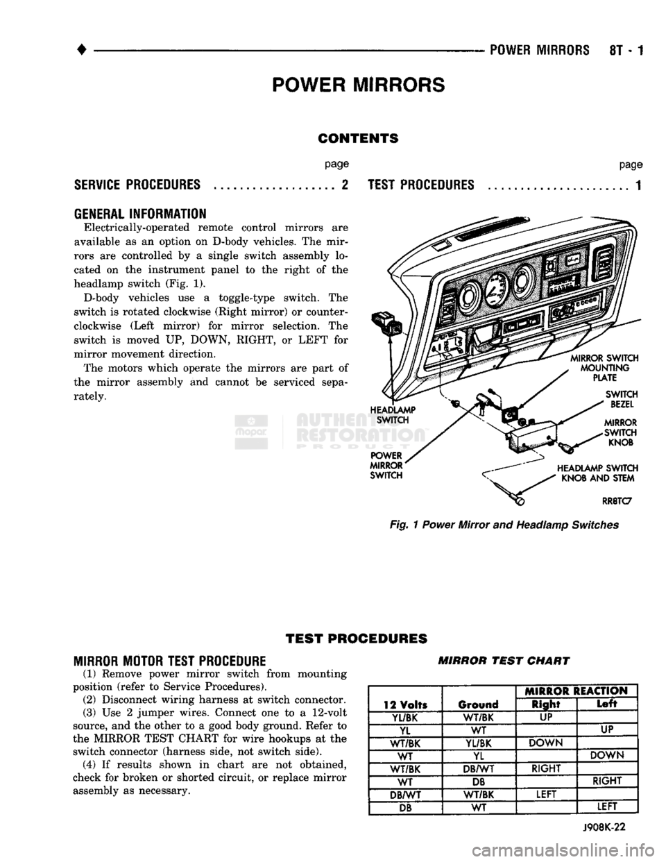
Electrically-operated remote control mirrors are
available as an option on D-body vehicles. The mir
rors are controlled by a single switch assembly lo
cated on the instrument panel to the right of the
headlamp switch (Fig. 1). D-body vehicles use a toggle-type switch. The
switch is rotated clockwise (Right mirror) or counter
clockwise (Left mirror) for mirror selection. The
switch is moved UP, DOWN, RIGHT, or LEFT for
mirror movement direction. The motors which operate the mirrors are part of
the mirror assembly and cannot be serviced sepa
rately.
page
TEST PROCEDURES
...................... 1 Fig. 1 Power Mirror and Headlamp Switches
TEST
PROCEDURES
MIRROR MOTOR TEST PROCEDURE
(1) Remove power mirror switch from mounting
position (refer to Service Procedures). (2) Disconnect wiring harness at switch connector.
(3) Use 2 jumper wires. Connect one to a
12-volt
source, and the other to a good body ground. Refer to
the MIRROR TEST CHART for wire hookups at the switch connector (harness side, not switch side), (4) If results shown in chart are not obtained,
check for broken or shorted circuit, or replace mirror assembly as necessary. MIRROR
TEST
CHART
12 Volts Ground MIRROR REACTION
12 Volts Ground Right
Left
Yl/BK
1
WT/BK UP
YL WT UP
WT/BK
YL/BK
DOWN
WT YL DOWN
WT/BK DB/WT RIGHT
WT
DB
RIGHT
DB/WT WT/BK LEFT
DB
WT LEFT
J908K-22
Page 469 of 1502
8T - 2
POWER MIRRORS
•
MIRROR
SWITCH TEST PROCEDURE
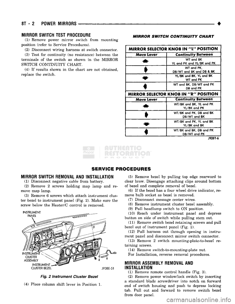
(1) Remove power mirror switch from mounting
position (refer to Service Procedures). (2) Disconnect wiring harness at switch connector.
(3) Test for continuity (no resistance) between the
terminals of the switch as shown in the MIRROR SWITCH CONTINUITY CHART. (4) If results shown in the chart are not obtained,
replace the switch.
MIRROR
SWITCH
CONTINUITY
CHART
MIRROR SELECTOR KNOB
IN
"L"
POSITION Move
Lever Continuity Between
WT
and BK
YL
and
PK
and
YL/BK
and PK
WT
and
PK,
DB/WT
and
BK
and
DB
&
BK
YL/BK
and
BK, YL
and
BK WT and PK
WT
and
BK, DB/WT
and PK
DB
and
PK
MIRROR SELECTOR KNOB
IN "R"
POSITION Move
Lever Continuity Between
WT/BK
and
BK,
YL and PK
YL/BK
and PK
•
WT/BK
and
PK, DB
and
BK
DB/WT
and
BK
WT/BK
and
PK, YL
and
BK
YL/BK
and
BK
«
WT/BK
and
BK, DB
and PK
DB/WT
and PK
J928T-6
SERVICE PROCEDURES
MIRROR
SWITCH REMOVAL AND INSTALLATION
(1) Disconnect negative cable from battery.
(2) Remove 2 screws holding map lamp and re
move map lamp. (3) Remove 6 screws which attach instrument clus
ter bezel to instrument panel (Fig. 2). Make sure the screw below the Heater/C control is removed.
INSTRUMENT
CLUSTER
BEZEL
J938E-51
Fig.
2 Instrument
Cluster
Bezel
(4) Place column shift lever in Position 1. (5) Remove bezel by pulling top edge rearward to
clear brow. Disengage attaching clips around bottom
of bezel and complete removal of bezel.
(6) If the bezel has a four wheel drive indicator, re
move bulb socket as bezel is removed. (7) Disconnect message center wires.
(8) Remove instrument cluster bezel assembly.
(9) Pull headlamp switch to ON position.
(10) Reach under instrument panel and depress
button on side of switch while pulling stem out.
(11) Remove switch bezel retaining screws and pull
bezel out of instrument panel (Fig. 1). (12) Pull harness out through opening in instru
ment panel and disconnect mirror switch connector.
(13) Remove 2 switch mounting-plate-to-bezel re
taining screws.
(14) Remove switch-to-mounting-plate nut.
For Installation, reverse removal procedures.
MIRROR
ASSEMBLY
REMOVAL
AND
INSTALLATION
(1) Remove remote control handle (Fig. 3).
(2) Remove power window/lock switch by inserting
a standard blade screwdriver into notch on forward
end of switch housing and push to depress locking
tab.
Pull out and forward to remove switch bezel
from door panel.
Page 1001 of 1502
19-40
STEERING
•
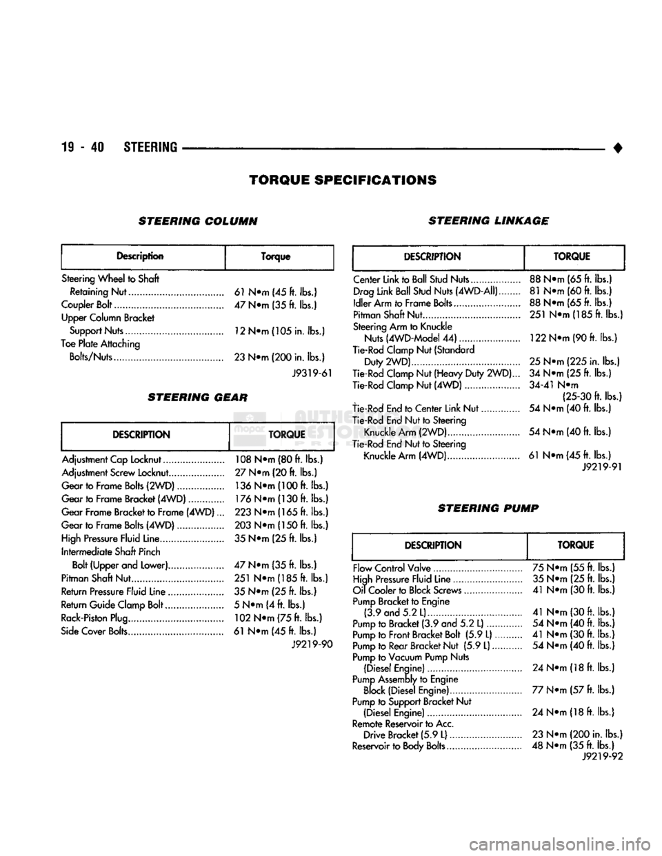
TORQUE
SPECIFICATIONS
STEERING COLUMN STEERING LINKAGE
Description Torque
Steering Wheel to Shaft Retaining Nut 61 N»m (45 ft. lbs.)
Coupler Bolt 47 N»m (35 ft. lbs.) Upper Column Bracket
Support Nuts 12N*m(105in. lbs.)
Toe Plate Attaching
Bolts/Nuts 23 N«m (200 in. lbs.)
J9319-61
STEERING
GEAR
DESCRIPTION
TORQUE
Adjustment Cap Locknut 108 N»m (80 ft. lbs.)
Adjustment Screw Locknut.... 27 N®m (20 ft. lbs.)
Gear to Frame Bolts (2WD) 136
N®m
(100 ft. lbs.)
Gear to Frame Bracket (4WD) 176
N®m
(130 ft. lbs.)
Gear Frame Bracket to Frame (4WD)... 223 N*m (165 ft. lbs.)
Gear to Frame Bolts (4WD) 203 N*m (150 ft. lbs.)
High Pressure Fluid Line. 35 N*m (25 ft. lbs.)
Intermediate Shaft Pinch Bolt (Upper and Lower) 47 N»m (35 ft. lbs.)
Pitman Shaft Nut 251 N»m (185 ft. lbs.)
Return Pressure Fluid Line 35 N*m (25 ft. lbs.)
Return Guide Clamp Bolt 5 N*m (4 ft. lbs.)
Rack-Piston Plug 102
N®m
(75 ft. lbs.)
Side Cover Bolts 61 N*m (45 ft. lbs.) J9219-90
DESCRIPTION
TORQUE
Center Link to Ball Stud Nuts..., Drag Link Ball Stud Nuts (4WD-AII)
Idler Arm to Frame Bolts...
Pitman Shaft Nut
Steering Arm to Knuckle Nuts (4WD-Model 44)
Tie-Rod Clamp Nut (Standard
Duty 2WD)....
Tie-Rod Clamp Nut (Heavy Duty
2WD).
Tie-Rod Clamp Nut (4WD)
tie-Rod End to Center Link Nut.
Tie-Rod End Nut to Steering
Knuckle
Arm
(2WD)..
Tie-Rod End Nut to Steering Knuckle Arm (4WD) 88 N®m (65 ft. lbs.)
81 N®m (60 ft. lbs.)
88 N*m (65
ft.
lbs.) 251 NTn(185ft. lbs.)
122 N*m (90
ft.
lbs.)
25
N^m (225 in. lbs.)
34 N«m (25
ft.
lbs.)
34-41 N«m (25-30 ft. lbs.)
54 N«m (40
ft.
lbs.)
54 N*m (40
ft.
lbs.)
61 N«m(45ft. lbs.)
J9219-91
STEERING PUMP
DESCRIPTION
TORQUE
Flow Control Valve
High Pressure Fluid Line
Oil Cooler to Block Screws
Pump Bracket to Engine (3.9 and 5.2 L)..
Pump to Bracket (3.9 and 5.2
L)....
Pump to Front Bracket Bolt (5.9 L).
Pump to Rear Bracket Nut (5.9
L)
Pump to Vacuum Pump Nuts
(Diesel Engine)
Pump Assembly to Engine Block (Diesel Engine)
Pump to Support Bracket Nut (Diesel Engine)
Remote Reservoir to Acc, Drive Bracket (5.9
L)
Reservoir to Body Bolts 75 N®m (55
ft.
lbs.)
35 N«*m (25 ft. lbs.)
41 N*m (30
ft.
lbs.)
41 N*m (30
ft.
lbs.) 54 N®m (40
ft.
lbs.)
41 N*m (30
ft.
lbs.) 54 N*m (40
ft.
lbs.)
24 N®m
(18
ft.
lbs.)
77 N*m (57
ft.
lbs.) 24 NTH (18
ft.
lbs.)
23 N*m (200 in. lbs.)
48 N«m (35
ft.
lbs.) J9219-92