1993 DODGE TRUCK headlamp
[x] Cancel search: headlampPage 47 of 1502
0
- 28
LUBRICATION
AND
MAINTENANCE
•
CHASSIS AND BODY
page
Body
Component Mechanisms
32
Front
Suspension
Ball
Joints
28
Front
Wheel Bearings
29
Headlamps
32
Lower
and
Upper Suspension
Arm
Bushings
.... 30
Manual
Steering Gear
28
STEERING
LINKAGE
INSPECTION When
a
vehicle
is
raised
for
maintenance under
the vehicle,
all
steering components should
be
checked.
LUBRICATION SCHEDULE The steering linkage
is
lubricated with
a
chassis
lubricant. However,
it is
recommended that
the
link
age
be
inspected
and
lubricated after each:
•
24 000 km
(15,000 miles) interval
or
every
6
months,
for 2WD
vehicles subject
to the
LIGHT
DUTY CYCLE Maintenance Schedule
•
9 600 km
(6,000 miles) interval
or
every
6
months,
for
2WD
vehicles subject
to the
HEAVY DUTY
CY
CLE Maintenance Schedule
•
12 000 km
(7,500 miles) interval
or
every
6
months,
for 4WD
vehicles subject
to the
LIGHT DUTY CYCLE Maintenance Schedule
•
9 600 km
(6,000 miles) interval
or
every
6
months,
for
4WD
vehicles subject
to the
HEAVY DUTY
CY
CLE Maintenance Schedule.
LUBRICATION (1) Inspect
the
steering linkage
for
looseness
and
excessive wear. (2) Replace,
all
ruptured seals
and
damaged steer
ing linkage components. Damaged seals should
be re
placed
to
prevent leakage
and
contamination
of the
lubricant.
CAUTION:
Use
care
to
prevent lubricant from
con
tacting
the
brake rotors.
(3) Lubricate
the
steering linkage:
• Clean
the
Zerk type lubrication fittings
on the tie-
rod
and
center link ball-stud ends
• Lubricate
the
ball studs with MOPAR®Multi-Mile- age Lubricant
• Wipe
the
excess lubricant from
the
exterior sur
faces
of the
ball joints
page
Power
Brake System
30
Power
Steering System
. . 29
Rear
Wheel Bearings
30
Speedometer Cable
33
Steering Linkage
28
Tires
32
FRONT
SUSPENSION
BALL JOINTS
INSPECTION When
a
vehicle
is
raised
for
lubrication/general
maintenance,
the
ball joints should
be
inspected.
LUBRICATION SCHEDULE The front suspension ball joints
are
lubricated dur
ing manufacture with
a
long-life chassis lubricant.
However,
it is
recommended that
the
ball joints
be
inspected
and the
studs lubricated:
•
At
each
36 000 km
(22,500 miles) interval
or
every
2 years,
for
vehicles subject
to the
LIGHT DUTY
CY
CLE Maintenance Schedule
•
At
each
9 600 km
(6,000 miles) interval
or
every
2
years,
for
vehicles subject
to the
HEAVY DUTY
CY
CLE Maintenance Schedule.
4WD vehicles that
are
frequently driven
off-
road should
be
lubricated
at
every engine
oil
change.
LUBRICATION (1) Inspect
the
front suspension. Examine
the
ball
studs
for
looseness
and
excessive wear. (2) Replace
all
torn ball-stud seals
and
damaged
ball joints. Damaged seals should
be
replaced
to
pre vent leakage
and
contamination.
CAUTION:
Use
care
to
prevent lubricant from
con
tacting
the
brake rotors.
(3) Lubricate
the
ball studs:
• Clean
the
Zerk type lubrication fittings
on the
ball-stud ends
• Lubricate
the
ball studs with MOPAR®Multi-Mile-age Lubricant
• Wipe
the
excess lubricant from
the
exterior sur
faces
of the
ball joints
MANUAL
STEERING
GEAR
LUBRICATION Manual steering gears
are
permanently lubricated
during manufacture. Periodic lubrication
is not
nec
essary.
Page 51 of 1502
0
- 32
LUBRICATION
AND
MAINTENANCE
•
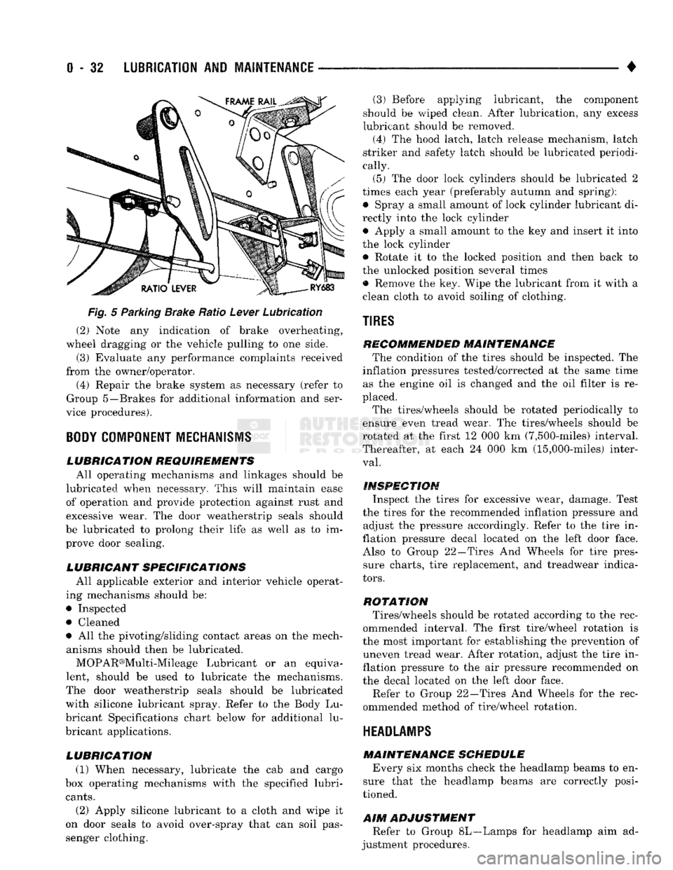
Fig.
5 Parking Brake Ratio Lever Lubrication (2) Note any indication of brake overheating,
wheel dragging or the vehicle pulling to one side.
(3) Evaluate any performance complaints received
from the owner/operator. (4) Repair the brake system as necessary (refer to
Group 5—Brakes for additional information and ser
vice procedures).
BODY
COMPONENT
MECHANISMS
LUBRICATION REQUIREMENTS
All operating mechanisms and linkages should be
lubricated when necessary. This will maintain ease of operation and provide protection against rust and
excessive wear. The door weatherstrip seals should
be lubricated to prolong their life as well as to im prove door sealing.
LUBRICANT SPECIFICATIONS
All applicable exterior and interior vehicle operat
ing mechanisms should be:
• Inspected • Cleaned
• All the pivoting/sliding contact areas on the mech anisms should then be lubricated.
MOPAR®Multi-Mileage Lubricant or an equiva
lent, should be used to lubricate the mechanisms.
The door weatherstrip seals should be lubricated
with silicone lubricant spray. Refer to the Body Lu
bricant Specifications chart below for additional lu
bricant applications.
LUBRICATION
(1) When necessary, lubricate the cab and cargo
box operating mechanisms with the specified lubri
cants.
(2) Apply silicone lubricant to a cloth and wipe it
on door seals to avoid over-spray that can soil pas
senger clothing. (3) Before applying lubricant, the component
should be wiped clean. After lubrication, any excess
lubricant should be removed.
(4) The hood latch, latch release mechanism, latch
striker and safety latch should be lubricated periodi
cally.
(5) The door lock cylinders should be lubricated 2
times each year (preferably autumn and spring): • Spray a small amount of lock cylinder lubricant di
rectly into the lock cylinder
• Apply a small amount to the key and insert it into
the lock cylinder • Rotate it to the locked position and then back to
the unlocked position several times
• Remove the key. Wipe the lubricant from it with a
clean cloth to avoid soiling of clothing.
TIRES
RECOMMENDED MAINTENANCE
The condition of the tires should be inspected. The
inflation pressures tested/corrected at the same time as the engine oil is changed and the oil filter is re
placed.
The tires/wheels should be rotated periodically to
ensure even tread wear. The tires/wheels should be
rotated at the first 12 000 km (7,500-miles) interval.
Thereafter, at each 24 000 km (15,000-miles) inter
val.
INSPECTION
Inspect the tires for excessive wear, damage. Test
the tires for the recommended inflation pressure and adjust the pressure accordingly. Refer to the tire in
flation pressure decal located on the left door face. Also to Group 22—Tires And Wheels for tire pressure charts, tire replacement, and treadwear indica
tors.
ROTATION
Tires/wheels should be rotated according to the rec
ommended interval. The first tire/wheel rotation is
the most important for establishing the prevention of uneven tread wear. After rotation, adjust the tire in
flation pressure to the air pressure recommended on
the decal located on the left door face.
Refer to Group 22—Tires And Wheels for the rec
ommended method of tire/wheel rotation.
HEADLAMPS
MAINTENANCE SCHEDULE
Every six months check the headlamp beams to en
sure that the headlamp beams are correctly posi
tioned.
AIM
ADJUSTMENT
Refer to Group 8L—Lamps for headlamp aim ad
justment procedures.
Page 329 of 1502
8A
- 8
ELECTRICAL
BATTERY
DIAGNOSTICS
CHART
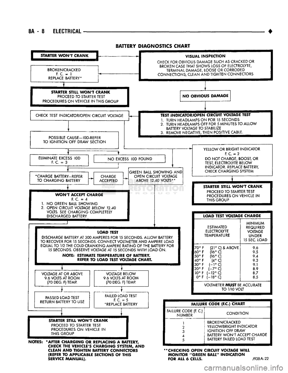
STARTER
WONT
CRANK
BROKEN/CRACKED
F. C.
= 1
REPLACE
BATTERY* VISUAL
INSPECTION
CHECK
FOR OBVIOUS DAMAGE SUCH AS CRACKED OR
BROKEN
CASE
THAT
SHOWS
LOSS
OF ELECTROLYTE,
TERMINAL DAMAGE, LOOSE OR CORRODED
CONNECTIONS, CLEAN AND
TIGHTEN
CONNECTORS
STARTER
STILL
WONT
CRANK
PROCEED
TO STARTER TEST
PROCEDURES
ON VEHICLE IN THIS GROUP NO OBVIOUS DAMAGE
CHECK
TEST INDICATOR/OPEN CIRCUIT VOLTAGE
POSSIBLE
CAUSE—I0D-REFER
TO
IGNITION
OFF DRAW SECTION TEST INDICATOR/OPEN CIRCUIT VOLTAGE TEST
1.
TURN
HEADLAMPS ON FOR 15 SECONDS
2.
TURN
HEADLAMPS OFF FOR
5
MINUTES TO ALLOW BATTERY VOLTAGE TO STABILIZE
3. REMOVE NEGATIVE,
THEN
POSITIVE CABLE.
ELIMINATE
EXCESS
F. C.
= 3
IOD
NO
EXCESS
IOD FOUND
•CHARGE
BATTERY-REFER TO CHARGING BATTERY
CHARGE
ACCEPTED
GREEN
BALL SHOWING AND
OPEN CIRCUIT VOLTAGE
ABOVE
12.40
VOLTS**
WONT
ACCEPT CHARGE F.
C = 4
1.
NO
GREEN BALL SHOWING
2. OPEN CIRCUIT VOLTAGE BELOW
12.40
VOLTS. SEE CHARGING COMPLETELY
DISCHARGED
BATTERY YELLOW OR BRIGHT INDICATOR
F.
C.
= 2
DO NOT CHARGE, BOOST, OR
TEST, ELECTROLYTE BELOW INDICATOR. REPLACE BATTERY,
CHECK
CHARGING SYSTEM
T
STARTER
STILL
WONT
CRANK
PROCEED
TO STARTER TEST
PROCEDURES
ON VEHICLE
IN
THIS GROUP LOAD TEST
DISCHARGE
BATTERY AT
300
AMPERES
FOR
15
SECONDS.
ALLOW BATTERY
TO RECOVER FOR
15
SECONDS.
CONNECT VOLTMETER AND AMPERE LOAD EQUAL TO
1/2
THE COLD CRANKING AMPERE RATING OF THE BATTERY FOR 15
SECONDS.
OBSERVE VOLTAGE AT 15 SECONDS
WITH
LOAD ON.
NOTE: ESTIMATE TEMPERATURE
OF
BATTERY.
REFER
TO
LOAD TEST VOLTAGE CHART. VOLTAGE AT OR ABOVE
9.6 VOLTS AT ROOM (70 DEG. F) TEMP. VOLTAGE BELOW
9.6 VOLTS AT ROOM (70 DEG. F) TEMP.
PASSED
LOAD TEST
RETURN BATTERY TO USE FAILED LOAD TEST
F. C.
= 5
*
REPLACE
BATTERY LOAD TEST VOLTAGE CHARGE
ESTIMATED
ELECTROLYTE
TEMPERATURE
70°
60°
50°
40° 30°
20° 10° 0° (21°
C)& ABOVE
(16° C
(16°
C (4°
C
H°C
1-7°
C
(-12°C
(-18°C
MINIMUM
REQUIRED VOLTAGE UNDER
15 SEC. LOAD 9.6
9.5
9.4 9.3 9.1
8.9
8.7
8.5 VOLTMETER MUST BE ACCURATE
TO
1/10
VOLT
STARTER
ST8LL
WONT
CRANK
PROCEED
TO
STARTER TEST
PROCEDURES
ON
VEHICLE
IN
THIS GROUP
NOTES:
* AFTER CHARGING
OR
REPLACING
A
BATTERY,
CHECK
THE VEHICLE'S CHARGING SYSTEM,
AND
CLEAN
AND
TIGHTEN
BATTERY CONNECTORS (REFER
TO
APPLICABLE SECTIONS
OF
THIS
SERVICE
MANUAL). FAILURE CODE
(F.C)
CHART
FAILURE CODE (R
C)
NUMBER
CONDITION
1
2
3
4
5
BROKEN/CRACKED
YELLOW/BRIGHT INDICATOR
IGNITION
OFF DRAW
BATTERY
WON'T
ACCEPT CHARGE BATTERY FAILED LOAD TEST
** CHECKING OPEN CIRCUIT VOLTAGE
WILL
MONITOR ''GREEN BALL" INDICATION
FOR ALL
6
CELLS.
J938A-22
Page 394 of 1502
INSTRUMENT PANEL
AND
GAUGES
8E - 13
INSTRUMENT
PANEL MAP LAMP
BRACKET
HEADLAMP
SWITCH
CLUSTER
ASSEMBLY
HEADLAMP
SWITCH
MOUNTING
NUT CARGO LAMP
SWITCH
BEZEL
AND
APPLIQUE
HEADLAMP
KNOB
AND
STEM
BRACKET-AAAP LAMP
MOUNTING
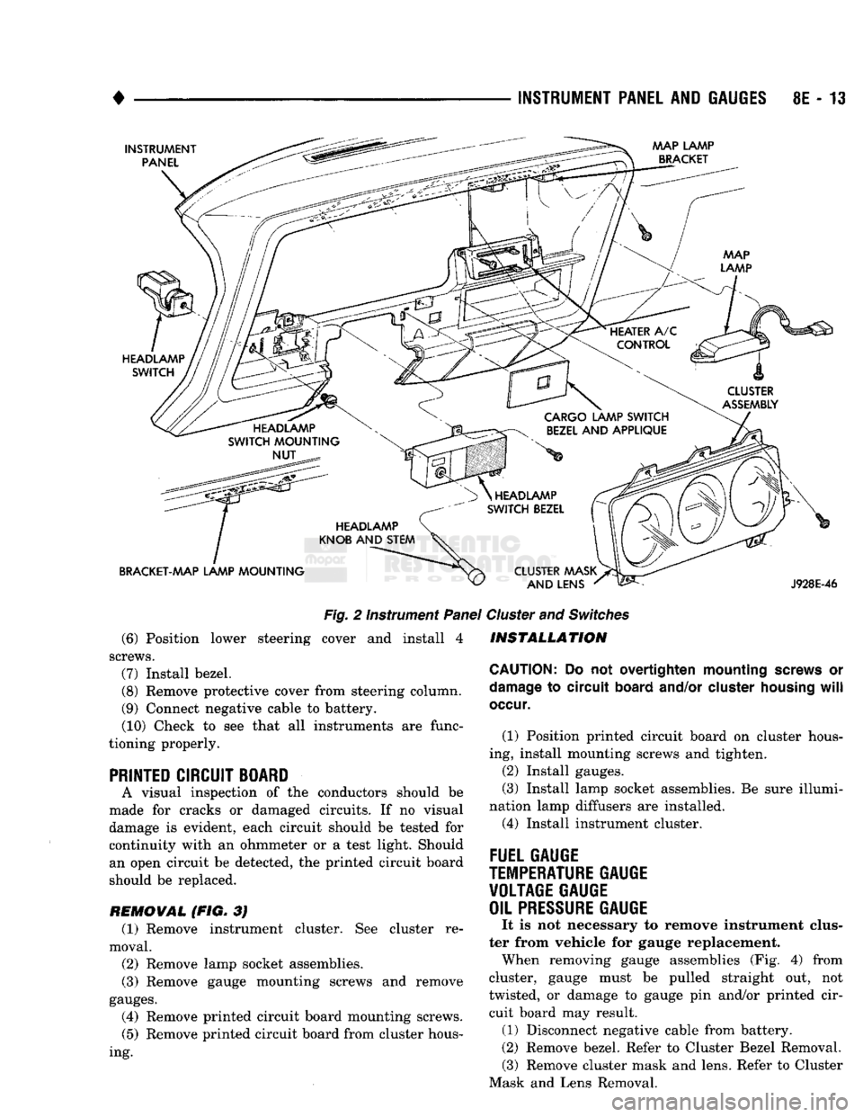
Fig.
2 Instrument
Panel
(6) Position lower steering cover and install 4
screws.
(7)
Install bezel.
(8)
Remove protective cover from steering column.
(9) Connect negative cable to battery. (10) Check to see that all instruments are func
tioning properly.
PRINTED CIRCUIT BOARD
A visual inspection of the conductors should be
made for cracks or damaged circuits. If no visual
damage is evident, each circuit should be tested for continuity with an ohmmeter or a test light. Should an open circuit be detected, the printed circuit board
should be replaced.
REMOVAL (FIG. 3J (1) Remove instrument cluster. See cluster re
moval.
(2)
Remove lamp socket assemblies.
(3) Remove gauge mounting screws and remove
gauges.
(4) Remove printed circuit board mounting screws.
(5)
Remove printed circuit board from cluster hous
ing.
HEADLAMP
SWITCH
BEZEL
CLUSTER MASK AND LENS
J928E-46
Cluster
and
Switches
INSTALLATION
CAUTION:
Do not overtighten mounting
screws
or
damage
to circuit
board
and/or
cluster
housing
will
occur.
(1) Position printed circuit board on cluster hous
ing, install mounting screws and tighten.
(2)
Install gauges.
(3) Install lamp socket assemblies. Be sure illumi
nation lamp diffusers are installed. (4) Install instrument cluster.
FUEL GAUGE
TEMPERATURE
GAUGE VOLTAGE GAUGE
OIL
PRESSURE
GAUGE
It is not necessary to remove instrument clus
ter from vehicle for gauge replacement. When removing gauge assemblies (Fig. 4) from
cluster, gauge must be pulled straight out, not
twisted, or damage to gauge pin and/or printed cir cuit board may result. (1) Disconnect negative cable from battery.
(2)
Remove bezel. Refer to Cluster Bezel Removal. (3) Remove cluster mask and lens. Refer to Cluster
Mask and Lens Removal.
Page 398 of 1502
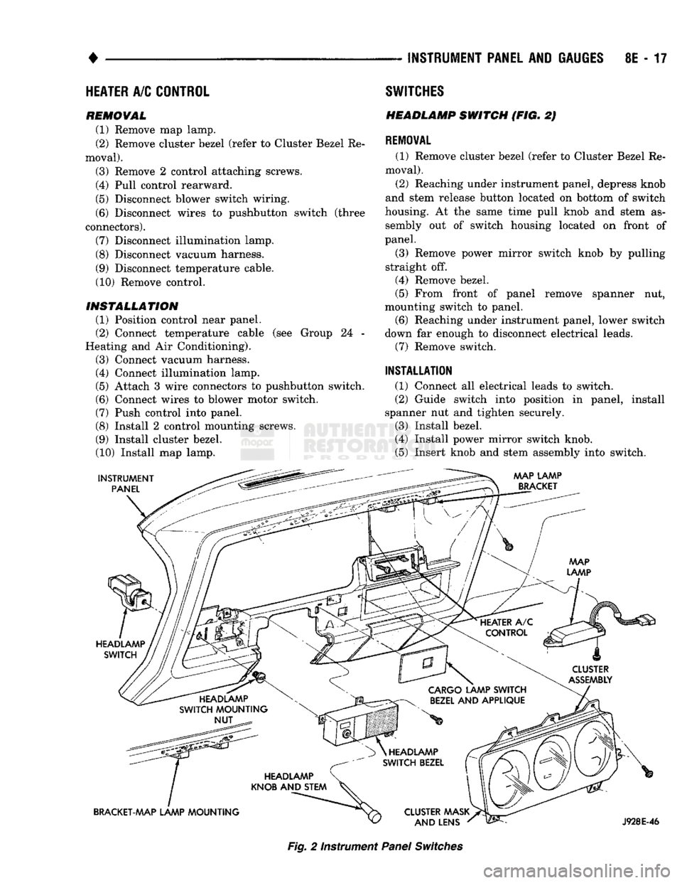
INSTRUMENT
PANEL
AND
GAUGES
8E - 17
HEATER
A/C
CONTROL
REMOVAL
(1) Remove map lamp.
(2) Remove cluster bezel (refer to Cluster Bezel Re
moval).
(3) Remove 2 control attaching screws.
(4) Pull control rearward.
(5) Disconnect blower switch wiring.
(6) Disconnect wires to pushbutton switch (three
connectors). (7) Disconnect illumination lamp.
(8) Disconnect vacuum harness.
(9) Disconnect temperature cable.
(10) Remove control.
INSTALLATION
(1) Position control near panel.
(2) Connect temperature cable (see Group 24 -
Heating and Air Conditioning).
(3) Connect vacuum harness. (4) Connect illumination lamp.
(5) Attach 3 wire connectors to pushbutton switch.
(6) Connect wires to blower motor switch.
(7) Push control into panel.
(8) Install 2 control mounting screws.
(9) Install cluster bezel.
(10) Install map lamp.
INSTRUMENT
PANEL SWITCHES
HEADLAMP
SWITCH
(FIG. 2)
REMOVAL
(1) Remove cluster bezel (refer to Cluster Bezel Re
moval).
(2) Reaching under instrument panel, depress knob
and stem release button located on bottom of switch
housing. At the same time pull knob and stem as sembly out of switch housing located on front of
panel.
(3) Remove power mirror switch knob by pulling
straight off.
(4) Remove bezel.
(5) From front of panel remove spanner nut,
mounting switch to panel. (6) Reaching under instrument panel, lower switch
down far enough to disconnect electrical leads. (7) Remove switch.
INSTALLATION
(1) Connect all electrical leads to switch.
(2) Guide switch into position in panel, install
spanner nut and tighten securely.
(3) Install bezel.
(4) Install power mirror switch knob.
(5) Insert knob and stem assembly into switch.
AAAP LAMP
BRACKET
HEADLAMP SWITCH
CLUSTER
ASSEMBLY
HEADLAMP
SWITCH MOUNTING NUT
CARGO
LAMP SWITCH
BEZEL
AND APPLIQUE
HEADLAMP
KNOB AND STEM
BRACKET-MAP LAMP MOUNTING HEADLAMP
SWITCH BEZEL
CLUSTER AAASK AND LENS
J928E-46
Fig.
2 Instrument
Panel
Switches
Page 429 of 1502
8J
- 2
TURN SIGNALS AND HAZARD WARNING FLASHER
•
FUSE
BLOCK
INSTRUMENT
PANEL
REAR
VIEW
HAZARD
WARNING
FLASHER
VIEW
IN DIRECTION OF
ARROW
RR8JC10
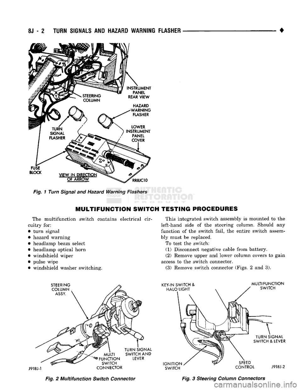
Fig.
1 Turn
Signal
and Hazard Warning
Flashers
MULTIFUNCTION
SWITCH TESTING PROCEDURES
The multifunction switch contains electrical cir
cuitry for:
• turn signal
• hazard warning
• headlamp beam select
• headlamp optical horn
• windshield wiper
• pulse wipe • windshield washer switching. This integrated switch assembly is mounted to the
left-hand side of the steering column. Should any
function of the switch fail, the entire switch assem
bly must be replaced.
To test the switch: (1) Disconnect negative cable from battery.
(2) Remove upper and lower column covers to gain
access to the switch connector. (3) Remove switch connector (Figs. 2 and 3).
Fig.
2 Multifunction
Switch
Connector
Fig.
3 Steering
Column
Connectors
Page 435 of 1502
8K - 4
WINDSHIELD WIPER
AND
WASHER
SYSTEMS
•
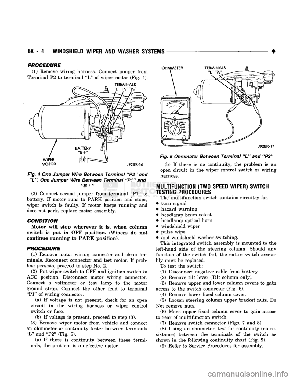
PROCEDURE (1) Remove wiring harness. Connect jumper from
Terminal P2 to terminal "L" of wiper motor (Fig, 4).
TERMINALS
Fig. 4 Om Jumper Wire Between Terminal "P2" and
"L".
One Jumper Wire Between Terminal "P1" and "B+" (2) Connect second jumper from terminal "PI" to
battery. If motor runs to PARK position and stops,
wiper switch is faulty. If motor keeps running and
does not park, replace motor assembly.
CONDITION Motor will stop wherever it is, when column
switch is put in OFF position. (Wipers do not
continue running to PARK position).
PROCEDURE
(1) Remove motor wiring connector and clean ter
minals. Reconnect connector and test motor. If prob lem persists, proceed to step No. 2.
(2) Put wiper switch to OFF and ignition switch to
ACC position. Disconnect motor wiring connector. Connect a voltmeter or test lamp to the motor
ground strap. Connect the other lead to terminal
"PI"
of wiring connector.
(a) If voltage is not present, check for an open
circuit in the wiring harness or wiper control
switch or fuse. (b) If voltage is present, proceed to step (3).
(3) Remove wiper motor from vehicle and connect
an ohmmeter or continuity tester between terminals
"L"
and "P2" (Fig. 5).
(a) If there is continuity between these termi
nals,
the problem is a defective motor. Fig. 5 Ohmmeter Between Terminal "L" and "P2"
(b) If there is no continuity, the problem is an
open circuit in the wiper control switch or wiring
harness.
MULTIFUNCTION
(TWO
SPEED WIPER) SWITCH
TESTING PROCEDURES
The multifunction switch contains circuitry for:
• turn signal
• hazard warning
• headlamp beam select
• headlamp optical horn
• windshield wiper
• pulse wipe
• and windshield washer switching. This integrated switch assembly is mounted to the
left-hand side of the steering column. Should any
function of the switch fail, the entire switch assem
bly must be replaced. To test the switch: (1) Disconnect negative cable from battery.
(2) Remove tilt lever (Tilt column only).
(3)
Remove upper and lower column covers to gain
access to the switch connector (Fig. 6). (4) Remove lower fixed column cover.
(5) Loosen steering column upper bracket nuts. Do
Not remove nuts.
(6)
Move upper fixed column cover to gain access
to rear of multifunction switch.
(7)
Remove switch connector (Figs. 7 and 8).
(8)
Using an ohmmeter, test for continuity (no re
sistance) between the terminals of the switch as
shown in the following continuity chart (Fig. 9).
(9)
Refer to Service Procedures for assembly.
Page 444 of 1502
•
LAMPS
LAMPS
8L - 1
CONTENTS
page page
BULB
APPLICATION 11 EXTERIOR
LAMPS
SERVICE
PROCEDURES
... 3
EXTERIOR
LAMPS
1 INTERIOR
LAMPS
10
EXTERIOR LAMPS
GENERAL
INFORMATION Each vehicle is equipped with various lamp assem
blies.
A good ground is necessary for proper lighting operation. When changing lamp bulbs check the socket for
corrosion. Clean corrosion with a wire brush. Coat
the inside of the socket lightly with Mopar® Multi- Purpose Grease or equivalent.
DIAGNOSTIC
PROCEDURES
Always begin any diagnosis by testing all of the
fuses and circuit breakers in the system. Refer to Group 8W, Wiring Diagrams. Conventional and halogen headlamps are inter
changeable. It is recommended that they not be in
termixed on a given vehicle.
MULTI-FUNCTION
SWITCH TESTING
PROCEDURES
The multi-function switch contains electrical cir
cuitry for:
• Headlamp Dimmer Switch
• Passing Lights
• Turn Signals
• Hazard Warning • Windshield Wiper
• Pulse Wiper
• Windshield Washer
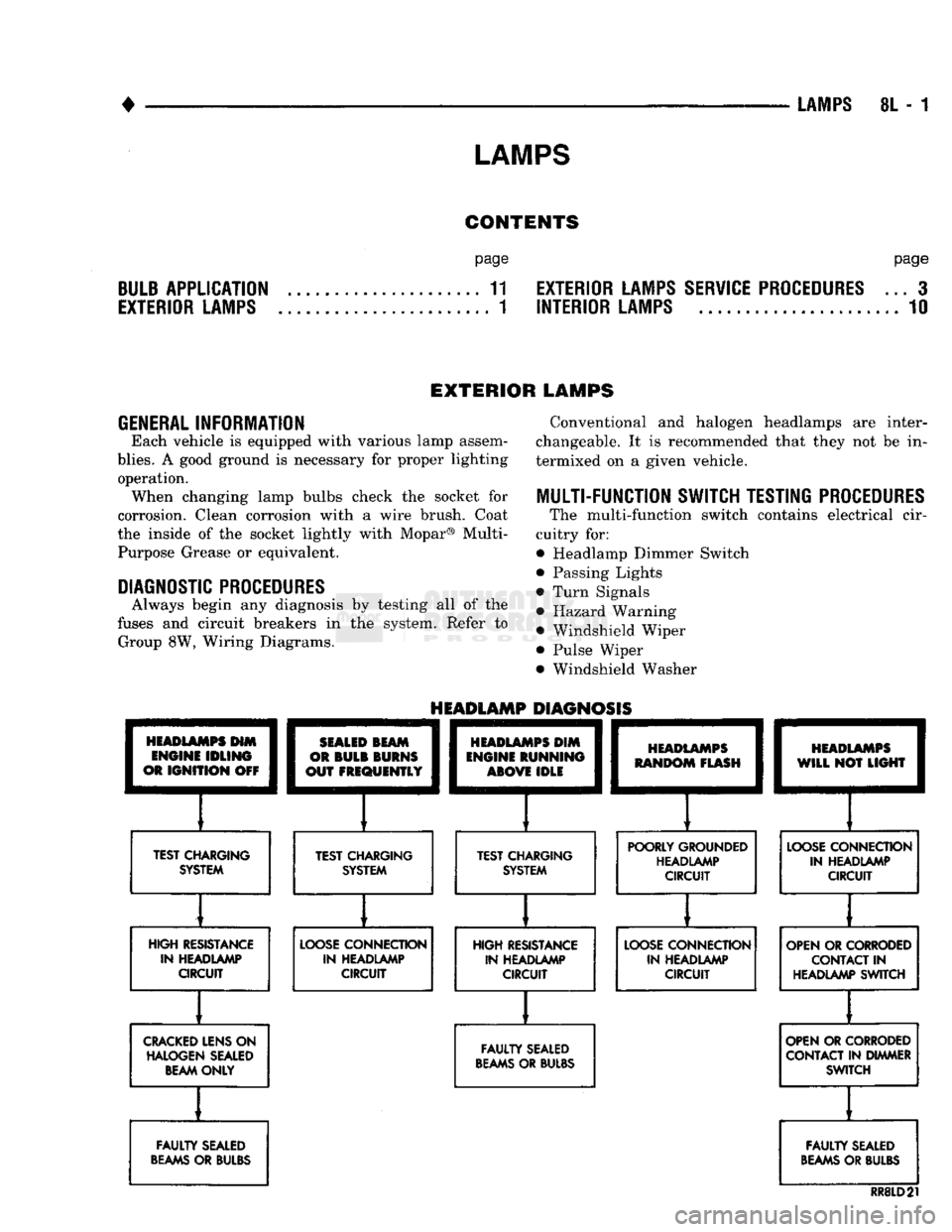
HEADLAMPS
HIM
ENGINE
IDLING
OR
IGNITION
OFF
TEST CHARGING
SYSTEM
HEADLAMP
DIAGNOSIS
SEALED
BEAM
OR
BULB
BURNS
OUT
FREQUENTLY
][
TEST CHARGING SYSTEM
HEADLAMPS
DIM
ENGINE
RUNNING
ABOVE
IDLE
][
TEST CHARGING SYSTEM
HEADLAMPS
RANDOM
FLASH
[
HEADLAMPS
WILL
NOT
LIGHT
POORLY GROUNDED HEADLAMP CIRCUIT
LOOSE
CONNECTION
IN HEADLAMP CIRCUIT
HIGH RESISTANCE IN HEADLAMP CIRCUIT
LOOSE
CONNECTION
IN HEADLAMP CIRCUIT HIGH RESISTANCE
IN HEADLAMP CIRCUIT
LOOSE
CONNECTION
IN HEADLAMP CIRCUIT OPEN OR CORRODED
CONTACT
IN
HEADLAMP SWITCH
CRACKED
LENS ON HALOGEN SEALED BEAM ONLY
FAULTY
SEALED
BEAMS
OR BULBS OPEN OR CORRODED
CONTACT IN DIMMER SWITCH
FAULTY
SEALED
BEAMS
OR BULBS
FAULTY
SEALED
BEAMS
OR BULBS
RR8LD21