1993 DODGE TRUCK frame
[x] Cancel search: framePage 4 of 1502
GROUP TAB LOCATOR
Introduction
0
Lubrication
and
Maintenance
2
Front Suspension
and
Axle
3
Rear Suspension
and
Axles
5
Brakes
6
Clutch
7
Cooling System
8
Electrical
9
Engines
11
Exhaust System
and
Intake
Manifold
13
Frame
and Bumpers
14
Fuel
System
16
Propeller Shafts
19
Steering
21
Transmission
and
Transfer Case
22
Wheels and Tires
23
Body Components
24
Heating
and Air
Conditioning
25
Emission Control Systems Component and System Index
Service Manual Comment Forms (Rear
of
Manual)
Page 7 of 1502
2 INTRODUCTION
•
MFD
BY
GAWR
FRONT
GAWR REAR
CHRYSLER
CORPORATION
DATE
OF MFR
GVWR
WITH
TIRES
WITH
TIRES
RIMS
AT
RIMS
AT
PSI
COLD
PSI
COLD
THIS
VEHICLE CONFORMS
TO
ALL APPLICABLE FEDERAL MOTOR VEHICLE SAFETY
STANDARDS
IN
EFFECT ON
THE
DATE
OF
MANUFACTURE SHOWN ABOVE.
SINGLE
DUAL
MDH:
BAR
CODE
VEHICLE MADE
IN
4648503
J9HN-25
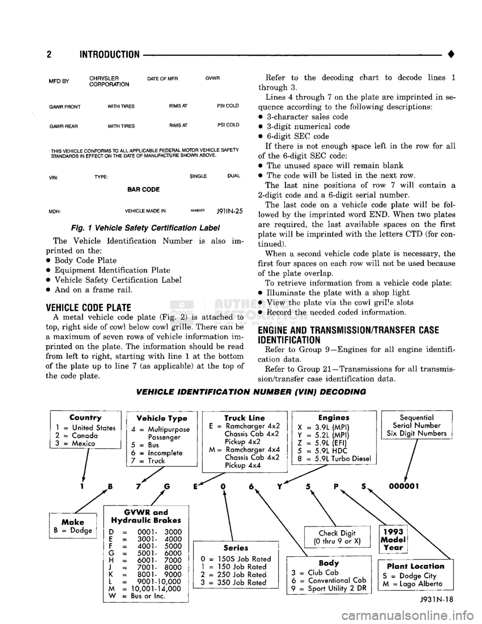
Fig. 1 Vehicle Safety Certification Label
The Vehicle Identification Number is also im
printed on the:
• Body Code Plate
• Equipment Identification Plate
• Vehicle Safety Certification Label
• And on a frame rail.
VEHICLE CODE PLATE
A metal vehicle code plate (Fig. 2) is attached to
top,
right side of cowl below cowl grille. There can be a maximum of seven rows of vehicle information im
printed on the plate. The information should be read
from left to right, starting with line 1 at the bottom
of the plate up to line 7 (as applicable) at the top of
the code plate. Refer to the decoding chart to decode lines 1
through 3.
Lines 4 through 7 on the plate are imprinted in se
quence according to the following descriptions:
• 3-character sales code • 3-digit numerical code
• 6-digit SEC code If there is not enough space left in the row for all
of the 6-digit SEC code:
• The unused space will remain blank
• The code will be listed in the next row.
The last nine positions of row 7 will contain a
2-digit code and a 6-digit serial number.
The last code on a vehicle code plate will be fol
lowed by the imprinted word END. When two plates
are required, the last available spaces on the first
plate will be imprinted with the letters CTD (for con tinued).
When a second vehicle code plate is necessary, the
first four spaces on each row will not be used because of the plate overlap.
To retrieve information from a vehicle code plate:
• Illuminate the plate with a shop light
• View the plate via the cowl grille slots
• Record the needed coded information.
ENGINE AND TRANSMISSION/TRANSFER CASE
IDENTIFICATION
Refer to Group 9—Engines for all engine identifi
cation data. Refer to Group 21—Transmissions for all transmis
sion/transfer case identification data.
VEHICLE IDENTIFICATION NUMBER (VIN) DECODING
Country
1
=
United States
2
=
Canada
3
=
Mexico Vehicle Type
4
=
Multipurpose
Passenger
5
=
Bus
6
=
Incomplete
7
=
Truck
GVWR
and
Hydraulic Brakes
0001 3001
4001
5001 6001
7001 8001
9001
10,001
Bus
or I
3000
4000
5000 6000
7000 8000
9000
10,000
14,000
nc.
Truck Line
E
=
Ramcharger
4x2
Chassis
Cab
4x2
Pickup
4x2
M
=
Ramcharger
4x4
Chassis
Cab
4x2
Pickup
4x4
Engines
X
=
3.9L
(MPI)
Y = 5.2L
(MPI)
Z
=
5.9L
(EFI)
5
=
5.9L HDC
8
=
5.9L Turbo Diesel Sequential
Serial Number
Six
Digit Numbers
Series
0 =
150S Job Rated
1
= 150
Job Rated
2
= 250
Job Rated
3
= 350
Job Rated
Body
3
=
Club Cab 6
=
Conventional Cab
9
=
Sport
Utility
2 DR
Plant Location
S
=
Dodge City
M
=
Lago
Alberto J931N-18
Page 29 of 1502
0-10
LUBRICATION
AND
MAINTENANCE
•
O.K.TO
JUMP
START BATTERY
CONDITION
INDICATOR DO NOT
JUMP
START J9100-26 DARKENED
INDICATOR
WITH
GREEN
DOT
•
LETTERS
Uk-
FLUID
Lt- E:L .
DARKENED
INDICATOR
NO
GREEN
DOT •
BATTERY CHARGE
10'//
• Ft UID
L
EVEl
OK
LIGHT
OR
BRIGHT
INDICATOR
•
RAT-cci,
C
H
A
P
C;
F
R^'^Owh
AM.w-GE
FlAf StIll BE
r-
•
!
F-
r tjr r
?
STA
F
•
r
O U n
C
AI:
Fig.
5
Battery
Condition indicator
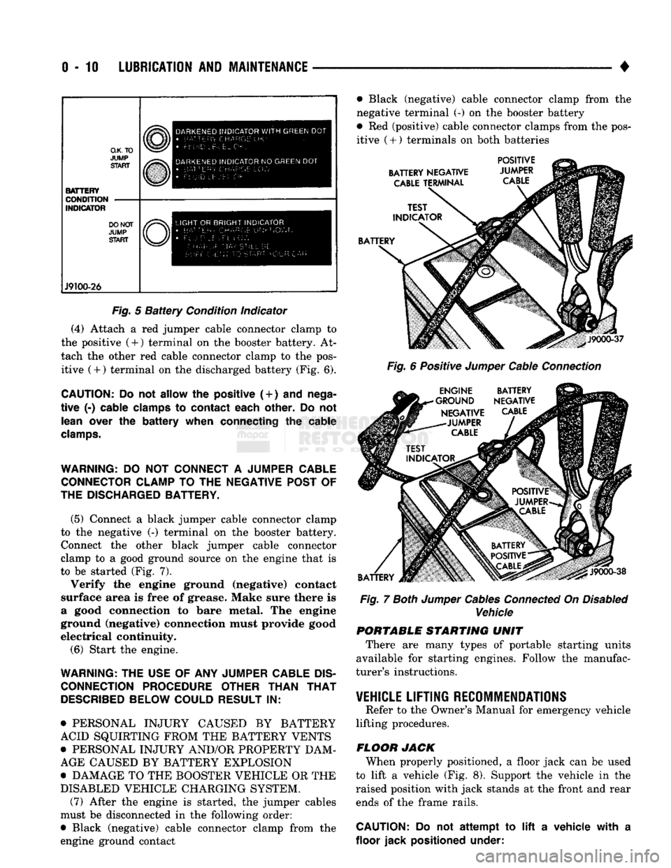
(4) Attach a red jumper cable connector clamp to
the positive (4-) terminal on the booster battery. At
tach the other red cable connector clamp to the pos itive (+) terminal on the discharged battery (Fig. 6).
CAUTION:
Do not
allow
the
positive (
+
)
and
nega
tive
(-)
cable clamps
to
contact each other.
Do not
lean over
the
battery when connecting
the
cable
clamps.
WARNING:
DO NOT
CONNECT
A
JUMPER CABLE CONNECTOR CLAMP
TO THE
NEGATIVE POST
OF
THE DISCHARGED BATTERY.
(5) Connect a black jumper cable connector clamp
to the negative (-) terminal on the booster battery. Connect the other black jumper cable connector
clamp to a good ground source on the engine that is
to be started (Fig. 7).
Verify the engine ground (negative) contact
surface area is free of grease. Make sure there is
a good connection to bare metal. The engine
ground (negative) connection must provide good
electrical continuity.
(6) Start the engine.
WARNING:
THE
USE
OF ANY
JUMPER CABLE
DIS
CONNECTION PROCEDURE OTHER THAN
THAT
DESCRIBED
BELOW COULD RESULT
IN:
• PERSONAL INJURY CAUSED BY BATTERY
ACID SQUIRTING FROM THE BATTERY VENTS
• PERSONAL INJURY AND/OR PROPERTY DAM
AGE CAUSED BY BATTERY EXPLOSION
• DAMAGE TO THE BOOSTER VEHICLE OR THE
DISABLED VEHICLE CHARGING SYSTEM. (7) After the engine is started, the jumper cables
must be disconnected in the following order:
• Black (negative) cable connector clamp from the
engine ground contact • Black (negative) cable connector clamp from the
negative terminal (-) on the booster battery
• Red (positive) cable connector clamps from the pos itive
(
+ ) terminals on both batteries
BATTERY NEGATIVE
CABLE
TERMINAL POSITIVE
JUMPER
CABLE
BATTERY
J9000-37
Fig.
6 Positive
Jumper
Cable
Connection
ENGINE BATTERY
•GROUND NEGATIVE NEGATIVE
CABLE
-JUMPER
CABLE
BATTERY
J9000-38
Fig.
7
Both
Jumper
Cables
Connected
On
Disabled
Vehicle PORTABLE STARTING UNIT
There are many types of portable starting units
available for starting engines. Follow the manufac
turer's instructions.
VEHICLE
LIFTING RECOMMENDATIONS
Refer to the Owner's Manual for emergency vehicle
lifting procedures.
FLOOR JACK When properly positioned, a floor jack can be used
to lift a vehicle (Fig. 8). Support the vehicle in the
raised position with jack stands at the front and rear ends of the frame rails.
CAUTION:
Do not
attempt
to lift a
vehicle with
a
floor jack positioned under:
Page 30 of 1502

LUBRICATION
AND
MAINTENANCE
0-11
J
DRIVE-ON
HOIST
I
FRAME
CONTACT
HOIST
TWIN
POST
CHASSIS
HOIST
FLOOR
JACK
RROOD30
Fig.
8 Correct Vehicle Lifting
Locations
An axle tube
A body side sill
A steering linkage component
A drive shaft
The engine or transmission oil pan
The fuel tank
• A front suspension arm Use the correct frame rail lifting locations only
(Fig. 8).
HOIST A vehicle can be lifted with:
• A single-post, frame-contact hoist
• A twin-post, chassis hoist
• A ramp-type, drive-on hoist
When a frame-contact type hoist is used, verify
that the lifting pads are positioned properly (Fig. 8).
WARNING:
WHEN
A
SERVICE
PROCEDURE
RE
QUIRES
THE
REMOVAL
OF
THE
REAR
AXLE,
FUEL
TANK,
OR
SPARE
TIRE,
EITHER:
• PLACE ADDITIONAL WEIGHT ON THE REAR
END OF THE VEHICLE
« ATTACH THE VEHICLE TO THE HOIST
« PLACE JACK STANDS UNDER THE VEHICLE
FOR SUPPORT TO PREVENT TIPPING WHEN
THE CENTER OF BALANCE CHANGES
4WD VEHICLES A standard hoist can be used to lift a 4WD vehicle.
The hoist should be inspected for adequate clearance. The lift arms, pads or ramps should be adjusted to
ensure that there is adequate clearance (Fig. 9).
ADJUSTMENT
PAD
ii 7
MAINTAIN
CLEARANCE
HOIST
ARM
RK44
Fig.
9 Lifting 4WD Vehicle
With
Single-Post
Hoist—
Typical
When a twin-post hoist is used, a 4 x 4 x 12-inch
wood spacer also could be required. Place the wood spacer under the front axle (opposite the differential
housing). This will maintain balance and level lift ing.
CAUTION:
The
block
that
is
used must
be
secured in
a
safe manner. This
will
ensure
that
it
will
not un
balance
the
vehicle.
VEHICLE
TOWING
RECOMMENDATIONS
When it is necessary to tow a Ram Truck, the rec
ommended method is either:
• the sling-type, rear-end raised towing method; or
• the wheel-lift towing method with a tow dolly lo
cated under the front wheels. A vehicle with flat-bed hauling equipment can also
be used to transport a disabled vehicle.
SLING-TYPE
FLAT
BED
RR0OD29
Fig.
10 Tow Vehicles
With
Approved
Equipment
Page 31 of 1502

0 - 12
LUBRICATION
AND
MAINTENANCE
• A vehicle equipped with SAE approved sling-type
towing equipment can be used (Fig. 10). However,
many vehicles are equipped with air dams, spoilers, and/or ground effect panels. In this case a wheel-lift
towing vehicle or a flat-bed hauling vehicle is recom mended (Fig. 10). If a flat bed device is used, the ap
proach angle should not exceed 15 degrees.
GROUND CLEARANCE The lifted wheels of the disabled vehicle should be
a minimum of 10 cm (4 in.) off the ground. Make
sure there is enough clearance at the opposite end.
This is critical when towing over rough terrain. If necessary, the rear ground clearance can be increased by removing the wheels from the lifted end
and then towing with the lifted end closer to the
ground. If the rear wheels are removed, secure the
brake drums. A 20 cm (8 in.) ground clearance must
be maintained between brake drums or rotors and the ground.
SAFETY PRECAUTIONS The following safety precautions must be consid
ered when preparing for and during a vehicle towing operation:
• Remove exhaust pipe tips that interfere with the
tow sling and crossbar • Padding should be placed between the tow sling/
crossbar and any painted surfaces
• If the vehicle is damaged, secure the loose and pro
truding parts
• Always use a safety chain system that is indepen dent of the lifting and towing equipment
• When placing tow hooks on the rear axle, position them so they do not damage the brake tubing or
hoses
• Do not allow any of the towing equipment to con
tact the fuel tank
• Do not tow the vehicle by connecting to the front
or rear shock absorbers
• The operator should not go under a vehicle while
it is lifted by the towing equipment. The vehicle
should first be supported by safety stands
• Do not allow passengers in a vehicle being towed
• Observe all state and local laws involving warning signals, night illumination, speed, etc.
• Do not exceed a towing speed of 48 km/h (30 mph)
• Avoid towing distances of more than 24 km (15
miles) whenever possible • Do not attach tow chains or a tow sling to a
bumper, the steering linkage, the universal joints, or a drive shaft
REAR-END RAISED TOWING It is recommended that the rear-end raised towing
method be used. Vehicles can be towed with the front
wheels on the ground for extended distances at speeds not exceeding 48 km/h (30 mph) (Fig. 11). (1) Attach the J-hooks around the axle shaft tubes
outboard of the rear springs. (2) Position and center the sling under and for
ward of the rear bumper. (3) Attach safety chains (with pads) at each end of
the rear bumper.
(4) Turn the ignition switch to the OFF position to
unlock the steering wheel. (5) Clamp the steering wheel with the front wheels
in the straight ahead position.
CAUTION:
Do not use the steering
column
lock
to
secure
front
wheel
in the straight-ahead
position.
(6) Shift the transmission to NEUTRAL.
POSITION CENTER BAR FORWARD
OF
BUMPER
-
/
J-HOOKS OUTBOARD
OF
SPRINGS
RN967A
Fig. 11 Rear-End
Raised
Towing
FRONT'END RAISED TOWING If a vehicle cannot be towed from the rear, the
front-end raised towing method normally can be
used (Fig. 12). (1) Center the sling with the bumper and position
it at the frame front crossmember.
CAUTION:
Use tow
chains
with
J-hooks
for
con
necting
to the
disabled
vehicle's
lower
suspension
arms.
Never use
T-hooks.
(2) Route the J-hooks and tow chains over the
steering linkage outboard of the coil spring.
(3) Attach the J-hooks to the outer end of the
lower suspension arms.
(4) Raise the vehicle.
(5.) Attach the safety chains to the disabled vehicle
at the frame rails.
Vehicles equipped with a MANUAL TRANSMIS
SION can be towed with the rear wheels on the
Page 40 of 1502
•
LUBRICATION
AND
MAINTENANCE
0 - 21 ROUTINE INSPECTION
It is recommended that the drive belt(s) be rou
tinely inspected for cracks, fraying and excessive
wear. Replace as necessary.
EXHAUST SYSTEM
An exhaust system must be properly aligned to
prevent stress, leakage, and vehicle body contact.
MAINTENANCE SCHEDULE Inspect the exhaust system at the interval specified
in maintenance schedule.
INSPECTION Inspect for cracked or loose joints, corrosion dam
age,
and worn or broken hangers. Replace all compo
nents that are damaged. Do not attempt repair. Also,
inspect for the following conditions and correct as
necessary:
• Exhaust system leaks, misalignment • Contact with body panels or the frame
• Catalytic converter bulging or excessive heat dam
age
CAUTION:
A
catalytic converter
will
become
con
taminated
if
leaded gasoline
is
burned
in the en
gine.
If
this
occurs,
the
complete converter must
be
replaced.
AIR-CONDITIONER COMPRESSOR LUBRICANT
AND
REFRIGERANT
The lubricant level in the compressor should be
checked if there are indications that oil was lost.
Loss of lubricating oil usually accompanies a loss of
refrigerant. The presence of bubbles in sight glass in dicates that loss of refrigerant has occurred. For additional information involving the A/C sys
tem, refer to Group 24—Heater And Air Condition ing.
Page 57 of 1502
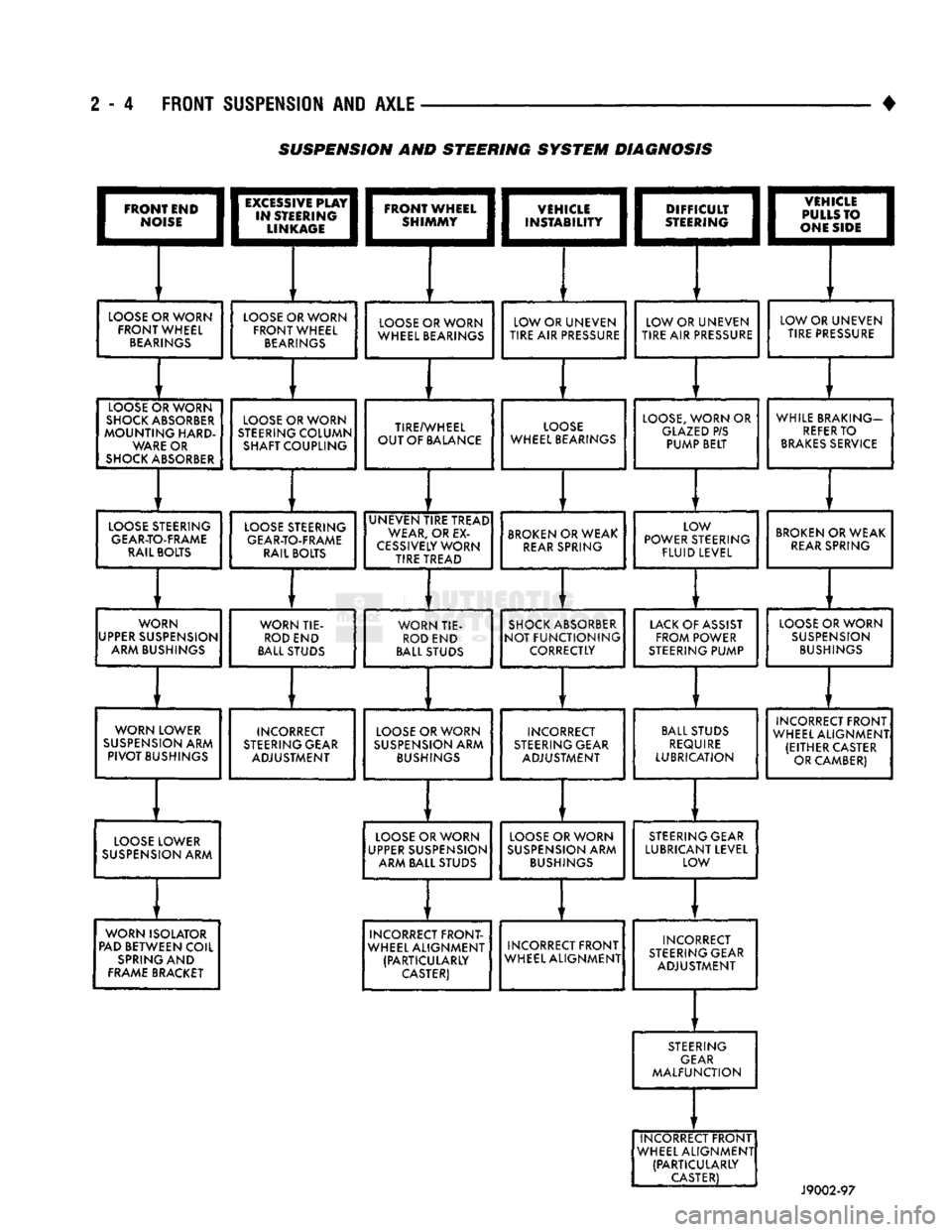
2 - 4 FRONT SUSPENSION AND AXLE
•
I
FRONT END
|
|*?£E;
LOOSE
OR WORN
FRONT WHEEL
BEARINGS
LOOSE
C
SHOCKS
MOUNTir
WAR
SHOCK
A )RWORN
JSORBER
nIG
HARD-
E
OR
BSORBER
EXCiSSIVE
PLAY
STEERING
LINKAGE
LOOSE
OR WORN
FRONT WHEEL
BEARINGS
LOOSE
C
STEERINC
SHAFT
C
)RWORN
7
COLUMN
OUPLING
DIFFICULT
STEERING
LOOSE
OR WORN
WHEEL BEARINGS
TIRE/V
OUT OF
f
VHEEL
JA
LANCE
LOW OR UNEVEN
TIRE
AIR
PRESSURE
LO(
WHEEL B
DSE
EARINGS
LOW OR UNEVEN
TIRE AIR
PRESSURE
1vsnciEi
I
1
PULLS
TO I
I
|
ONE SIDE
j
LOOSE,
WORN
OR
GLAZED
P/S PUMP BELT LOW OR UNEVEN
TIRE PRESSURE
WHILE BR
REFE
BRAKES
AKING—
R
TO
SERVICE
LOOSE
STEERING
GEAR-TO-FRAME
RAIL BOLTS
LOOSE
STEERING
GEAR-TO-FRAME
RAIL BOLTS UNEVEN TIRE TREAD
WEAR,
OR
EX
CESSIVELY
WORN TIRE TREAD
BROKEN
OR WEAK
REAR
SPRING LOW
POWER STEERING
FLUID
LEVEL
BROKEN
OR WEAK
REAR
SPRING
WORN
UPPER
SUSPENSION ARM BUSHINGS WORN TIE-
ROD
END
BALL
STUDS WORN TIE-
ROD
END
BALL
STUDS
SHOCK
ABSORBER
NOT FUNCTIONING
CORRECTLY
LACK
OF ASSIST
FROM POWER
STEERING
PUMP
LOOSE
OR WORN
SUSPENSION
BUSHINGS
WORN LOWER
SUSPENSION
ARM
PIVOT
BUSHINGS INCORRECT
STEERING
GEAR ADJUSTMENT
LOOSE
OR WORN
SUSPENSION
ARM
BUSHINGS
INCORRECT
STEERING
GEAR ADJUSTMENT
BALL
STUDS
REQUIRE
LUBRICATION INCORRECT FRONT
WHEEL ALIGNMENT (EITHER CASTER OR CAMBER)
LOOSE
LOWER
SUSPENSION
ARM
LOOSE
OR WORN
UPPER
SUSPENSION ARM BALL STUDS
LOOSE
OR WORN
SUSPENSION
ARM
BUSHINGS
STEERING
GEAR
LUBRICANT LEVEL LOW
WORN ISOLATOR
PAD
BETWEEN COIL
SPRING
AND
FRAME
BRACKET INCORRECT FRONT-
WHEEL ALIGNMENT (PARTICULARLY
CASTER)
INCORRECT FRONT
WHEEL ALIGNMENT INCORRECT
STEERING
GEAR ADJUSTMENT
STEERING
GEAR
MALFUNCTION
INCORRECT FRONT
WHEEL ALIGNMENT (PARTICULARLY
CASTER)
J9002-97
SUSPENSION AND STEERING
SYSTEM
DIAGNOSIS
Page 62 of 1502
4
FRONT
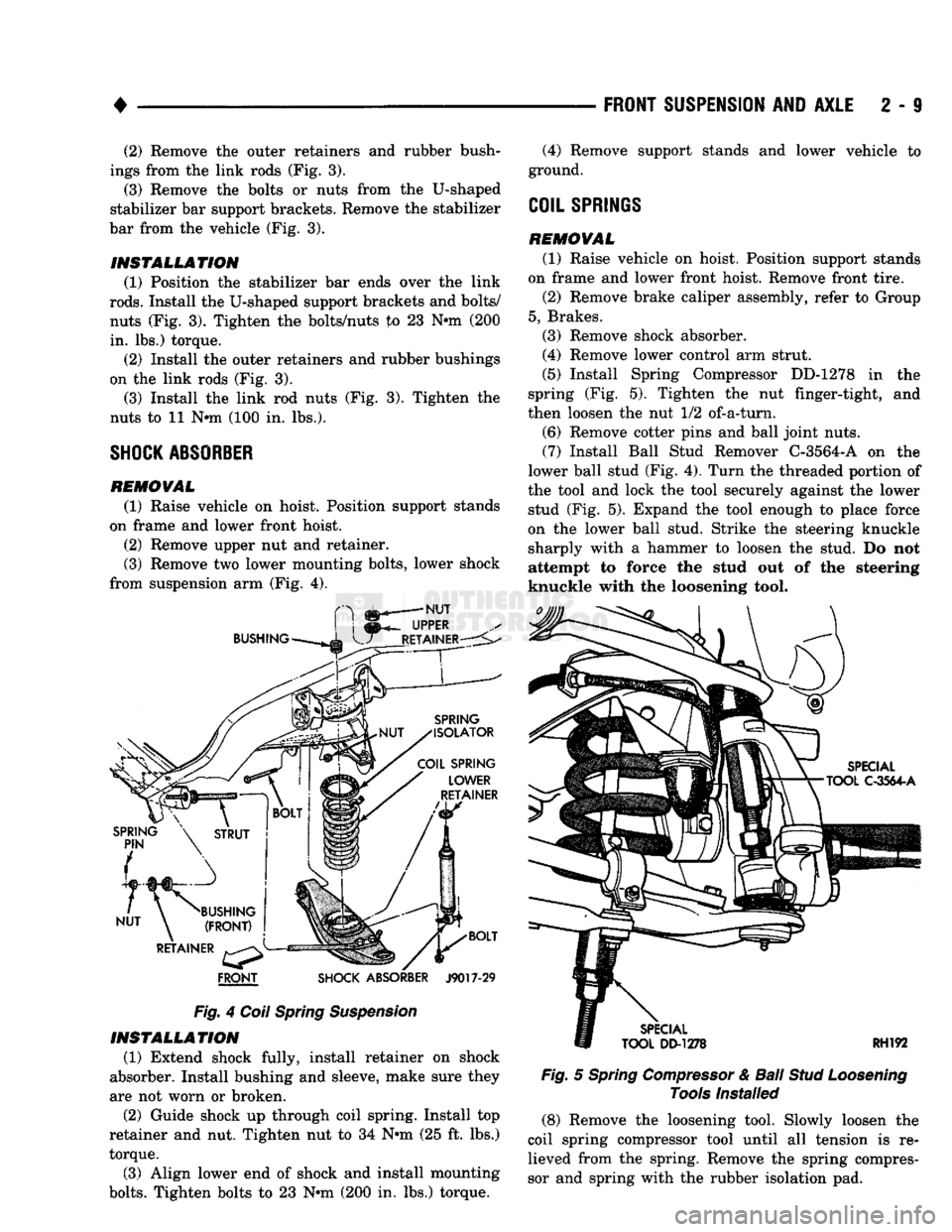
SHOCK ABSORBER
J9017-29
Fig.
4
Coil Spring Suspension INSTALLATION
(1) Extend shock fully, install retainer on shock
absorber. Install bushing and sleeve, make sure they
are not worn or broken.
(2) Guide shock up through coil spring. Install top
retainer and nut. Tighten nut to 34 Nnn (25 ft. lbs.)
torque.
(3) Align lower end of shock and install mounting
bolts.
Tighten bolts to 23 Nnn (200 in. lbs.) torque.
FRONT SUSPENSION
AND
AXLE
2 - i
Fig.
5
Spring Compressor
&
Ball
Stud Loosening
Tools
Installed (8) Remove the loosening tool. Slowly loosen the
coil spring compressor tool until all tension is re lieved from the spring. Remove the spring compres
sor and spring with the rubber isolation pad.
(2) Remove the outer retainers and rubber bush
ings from the link rods (Fig. 3).
(3) Remove the bolts or nuts from the U-shaped
stabilizer bar support brackets. Remove the stabilizer
bar from the vehicle (Fig. 3).
INSTALLATION
(1) Position the stabilizer bar ends over the link
rods.
Install the U-shaped support brackets and bolts/ nuts (Fig. 3). Tighten the bolts/nuts to 23 Nnn (200
in.
lbs.) torque. (2) Install the outer retainers and rubber bushings
on the link rods (Fig. 3).
(3) Install the link rod nuts (Fig. 3). Tighten the
nuts to 11 Nnn (100 in. lbs.).
SHOCK ABSORBER
REMOVAL
(1) Raise vehicle on hoist. Position support stands
on frame and lower front hoist.
(2) Remove upper nut and retainer.
(3) Remove two lower mounting bolts, lower shock
from suspension arm (Fig. 4). (4) Remove support stands and lower vehicle to
ground.
COIL
SPRINGS
REMOVAL
(1) Raise vehicle on hoist. Position support stands
on frame and lower front hoist. Remove front tire. (2) Remove brake caliper assembly, refer to Group
5, Brakes. (3) Remove shock absorber.
(4) Remove lower control arm strut.
(5) Install Spring Compressor DD-1278 in the
spring (Fig. 5). Tighten the nut finger-tight, and
then loosen the nut 1/2 of-a-turn.
(6) Remove cotter pins and ball joint nuts.
(7) Install Ball Stud Remover C-3564-A on the
lower ball stud (Fig. 4). Turn the threaded portion of
the tool and lock the tool securely against the lower stud (Fig. 5). Expand the tool enough to place force
on the lower ball stud. Strike the steering knuckle sharply with a hammer to loosen the stud. Do not
attempt to force the stud out of the steering
knuckle with the loosening tool.