1993 DODGE TRUCK automatic transmission fluid
[x] Cancel search: automatic transmission fluidPage 28 of 1502
•
LUBRICATION AND MAINTENANCE
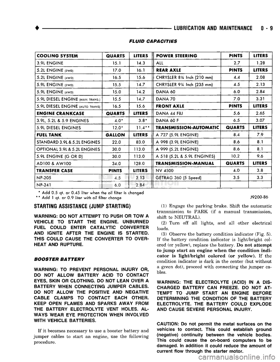
0 - 9 FLUID CAPACITIES
COOLING SYSTEM
QUARTS
LITERS
POWER STEERING PINTS
LITERS
3.9L ENGINE 15.1 14.3
ALL
2.7
1.28
5.2L ENGINE
(2WD)
17.0 16.1
REAR
AXLE
PINTS
LITERS
5.2L ENGINE
(4WD)
16.5 15.6
CHRYSLER
BVa
Inch
(210
mm) 4.4
2.08
5.9L ENGINE
(2WD)
15.5 14.7
CHRYSLER
9Va
Inch
(235
mm) 4.5
2.13
5.9L ENGINE
(4WD)
15.0 14.2
DANA
60 6.0
2.84
5.9L DIESEL ENGINE (MAN.TRANS.) 15.5 14.7
DANA
70 7.0
3.31
5.9L DIESEL ENGINE
(AUTO,
TRANS)
16.5 15.6
FRONT AXLE
PINTS
LITERS
ENGINE
CRANKCASE
QUARTS
LITERS
DANA
44
FBJ 5.6
2.65
3.9L,
5.2L & 5.9
ENGINES 4.0* 3.8*
DANA
60 F
6.5
3.07
5.9L DIESEL ENGINES 12.0*
11.4**
TRANSMISSION-AUTOMATIC
QUARTS
LITERS
FUEL TANK GALLON
LITERS
A
727 (5.9L
ENGINE) 8.4
7.9
STANDARD
3.9L & 5.2L ENGINES 22.0 83.0
A
998 (3.9L
ENGINE) 8.6
8.1
OPTIONAL 3.9L & 5.2L ENGINES 30.0 113.0
A
999 (5.2L
ENGINE) 8.6
8.1
5.9L ENGINE
{G
OR
D)
30.0 113.0
A
518 (5.2L & 5.9L
ENGINES) 10.2
9.6
AD 100
&
AW 100 34.0 128.0
TRANSMISSION-MANUAL
QUARTS
LITERS
TRANSFER
CASE
PINTS
LITERS
NV
4500
4.0
3.8
NP-205
4.5 2.13
GETRAG
360 (5
Speed)
3.5
3.3
NP-241
6.0
2.84
* Add
0.5 qt. or 0.45
liter
when
the oil filter
is
changed
*
*
Add
1 qt. or 0.9
liter
with
oil filter
change STARTING ASSISTANCE (JUMP STARTING)
WARNING:
DO NOT
ATTEMPT
TO
PUSH
OR
TOW
A
VEHICLE
TO
START
THE
ENGINE. UNBURNED FUEL COULD ENTER CATALYTIC CONVERTER
AND IGNITE AFTER
THE
ENGINE
IS
STARTED.
THIS COULD CAUSE
THE
CONVERTER
TO
OVER HEAT AND RUPTURE.
BOOSTER BATTERY
WARNING:
TO
PREVENT PERSONAL INJURY
OR,
DO
NOT
ALLOW BATTERY ACID
TO
CONTACT
EYES,
SKIN
OR
CLOTHING.
DO NOT
LEAN OVER
A
BATTERY WHEN CONNECTING JUMPER
CABLES.
DO
NOT
ALLOW
THE
POSITIVE
AND
NEGATIVE
CABLE
CLAMPS
TO
CONTACT EACH OTHER.
KEEP
OPEN FLAMES
AND
SPARKS
AWAY FROM
THE BATTERY ELECTROLYTE VENT HOLES.
AL
WAYS
WEAR
EYE
PROTECTION WHEN INVOLVED
WITH
VEHICLE BATTERIES.
If it becomes necessary to use a booster battery and
jumper cables to start an engine, use the following procedure.
J9200-86
(1) Engage the parking brake. Shift the automatic
transmission to PARK (if a manual transmission, shift to NEUTRAL).
(2) Turn off all lights, and all other electrical
loads.
(3)
Observe the battery condition indicator (Fig. 5).
If the battery condition indicator is light/bright col
ored (or yellow), replace the battery. Do not attempt
to jump start an engine when the condition indi
cator is light/bright colored (or yellow). If the
condition indicator is dark in the center (but without a green dot), proceed with connecting the jumper ca
bles.
WARNING:
THE
ELECTROLYTE (ACID)
IN A
DIS
CHARGED
BATTERY
CAN
FREEZE.
DO NOT AT
TEMPT
TO
JUMP START
AN
ENGINE BEFORE DETERMINING
THE
CONDITION
OF THE
BATTERY
ELECTROLYTE.
THE
BATTERY COULD EXPLODE
AND CAUSE SEVERE PERSONAL INJURY.
CAUTION:
Do not
permit
the
metal
surfaces
on the
vehicles
to
contact.
This
could
establish
ground
(negative)
continuity
between
the
vehicle
bodies.
This
could
cause
the
on-board
computers
to be
damaged.
In
addition
it
could
reduce
the
amount
of
current
flow
through
the
starter
motor.
Page 42 of 1502
•
LUBRICATION
AND
MAINTENANCE
0 - 23 GEAR SHIFTER BOOTS
Inspect the shifter boots periodically for stone and
heat damage. Replace, if necessary.
SEVERE DRIVING CONDITIONS The interval between the transmission drain and
refill maintenance should be decreased to:
• NV4500 manual transmission—every 29 000 km (18,000 miles)
• Automatic transmission—every 19 000 km (12,000
miles)
A severe driving condition includes:
• Extended operation with heavy cargo loads
• Driving in deep mud or snow
• Off-road operation (4WD)
• Trailer towing
• Operation as a commercial vehicle
• Snow plowing
MANUAL TRANSMISSIONS
INSPECTION/LUBE
OIL
LEVEL
The transmission should be checked for leaks when
other service is necessary under the vehicle. To check
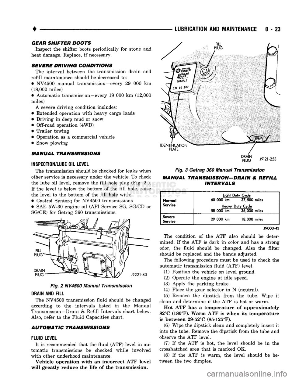
the lube oil level, remove the fill hole plug (Fig. 2 ). If the level is below the bottom of the fill hole, raise
the level to the bottom of the fill hole with:
• Castrol Syntorq for NV4500 transmissions
• SAE 5W-30 engine oil (API Service SG, SG/CD or
SG/CE) for Getrag 360 transmissions.
Fig.
2 NV4500 Manual
Transmission
DRAIN
AND
FILL
The NV4500 transmission fluid should be changed
according to the intervals listed in the Manual
Transmission—Drain & Refill Intervals chart below.
Also,
refer to the Fluid Capacities chart.
AUTOMATIC TRANSMISSIONS
FLUID
LEWEL
It is recommended that the fluid (ATF) level in au
tomatic transmissions be checked while involved
with other underhood maintenance.
Vehicle operation with an incorrect ATF level
will greatly reduce the life of the transmission.
Fig.
3 Getrag 360 Manual
Transmission
MANUAL TRANSMISSION-DRAIN & REFILL INTERVALS
Normal
Service
Light
Duty
Cycle
60 000
km
37,500
miles
Heavy
Duty
Cycle
58 000
km
36,000
miles
Severe
Service
29 000
km
18,000
miles
J9000-43
The condition of the ATF also should be deter
mined. If the ATF is dark in color and has a strong odor, the fluid should be changed. Also the filter should be replaced and the bands adjusted.
The following procedure must be used to check the
automatic transmission fluid (ATF) level.
(1) Position the vehicle on level ground.
(2) Operate the engine at idle speed.
(3) Apply the parking brake.
(4) Place the gear selector in N (neutral).
(5) Remove the dipstick from the tube. Wipe it
clean and determine if the ATF is hot or warm.
Hot ATF has a temperature of approximately
82°C (180°F). Warm ATF is when its temperature
is between 29-52°C (85-125°F). (6) Wipe the dipstick clean and completely insert it
into the tube. Remove the dipstick from the tube and
observe the ATF level.
(7) If the ATF is hot, the level should be in the
crosshatched area that is marked OK.
(8) If the ATF is warm, the level should be be
tween the two dimples.
Page 43 of 1502
0
- 24
LUBRICATION
AND
MAINTENANCE
•
CAUTION:
Do not
overfill
the
transmission.
(9) Adjust
the
level
of the ATF
accordingly.
It
is
important
to use the
correct fluid
in an
automatic transmission. MOPAR®ATF PLUS
(ATF Type
7176)
should
be
used. Dexron®
II
ATF
can be
used
if the
recommended fluid
is not
available,
(10) Insert
the
dipstick into
the
tube.
DRAIN, FILTER CHANGE, BAND ADJUSTMENT AND REFILL
The chart below lists
the
intervals
at
which
the
transmission should
be
serviced. Also, refer
to the
Fluid Capacities chart
for
fill capacity.
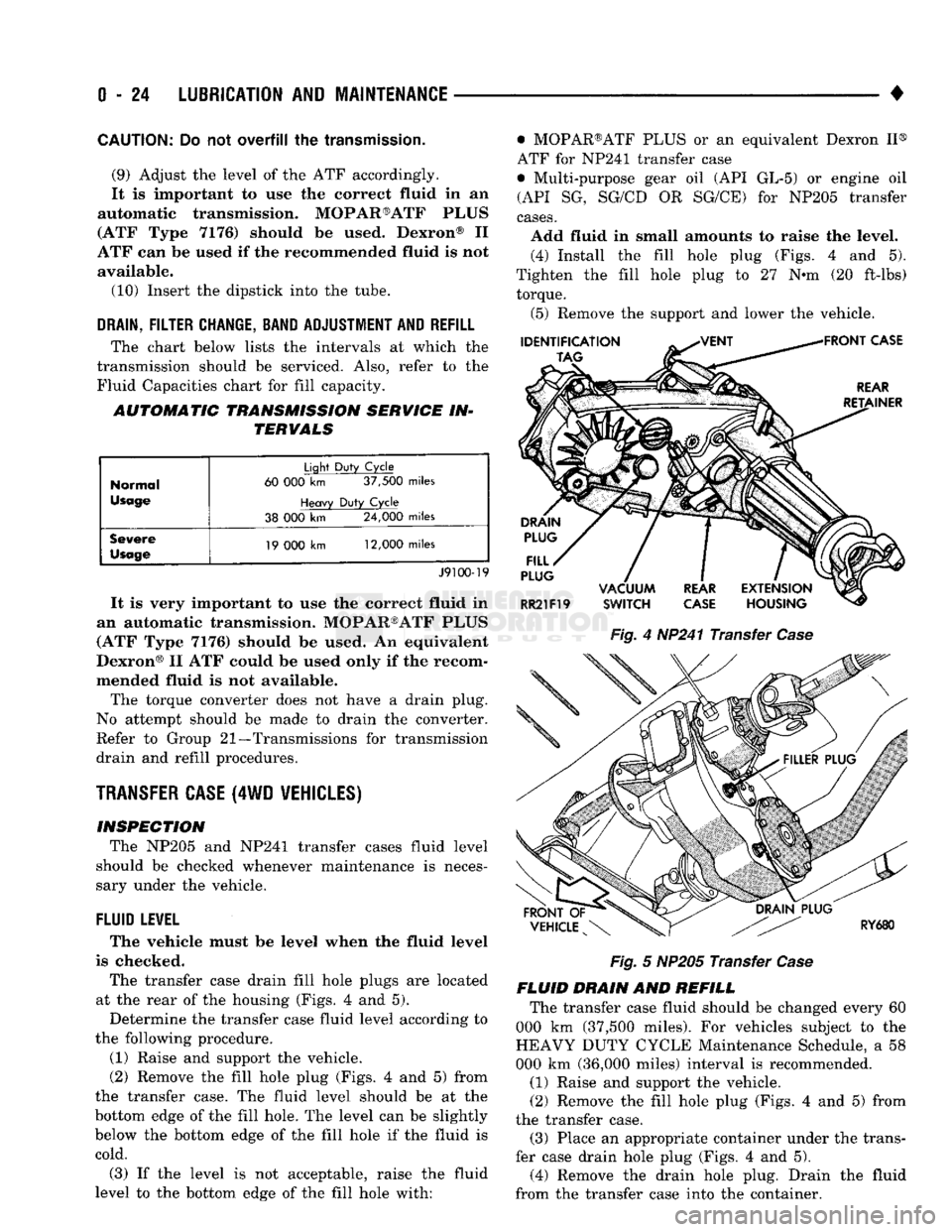
AUTOMATIC TRANSMISSION SERVICE
IN-
TERVALS
Normal
Usage
Light
Duty
Cycle
60 000
km
37,500
miles
Heavy
Duty
Cycle
38
000 km 24,000
miles
Severe
Usage
19 000 km 12,000
miles
J9100-19
It
is
very important
to use the
correct fluid
in
an automatic transmission. MOPAR®ATF PLUS
(ATF Type
7176)
should
be
used.
An
equivalent
Dexron®
II ATF
could
be
used only
if the
recom
mended fluid
is not
available.
The torque converter does
not
have
a
drain plug.
No attempt should
be
made
to
drain
the
converter.
Refer
to
Group
21
—Transmissions
for
transmission
drain
and
refill procedures.
TRANSFER
CASE
(4WD
VEHICLES)
INSPECTION The NP205
and
NP241 transfer cases fluid level
should
be
checked whenever maintenance
is
neces
sary under
the
vehicle.
FLUID
LEVEL
The vehicle must
be
level when
the
fluid level
is checked.
The transfer case drain fill hole plugs
are
located
at
the
rear
of the
housing (Figs.
4 and 5).
Determine
the
transfer case fluid level according
to
the following procedure.
(1) Raise
and
support
the
vehicle.
(2) Remove
the
fill hole plug (Figs.
4 and 5)
from
the transfer case.
The
fluid level should
be at the
bottom edge
of the
fill hole.
The
level
can be
slightly
below
the
bottom edge
of the
fill hole
if the
fluid
is
cold.
(3)
If the
level
is not
acceptable, raise
the
fluid
level
to the
bottom edge
of the
fill hole with: • MOPAR®ATF PLUS
or an
equivalent Dexron
II®
ATF
for
NP241 transfer case
• Multi-purpose gear
oil (API GL-5) or
engine
oil
(API
SG,
SG/CD
OR
SG/CE)
for
NP205 transfer
cases.
Add fluid
in
small amounts
to
raise
the
level. (4) Install
the
fill hole plug (Figs.
4 and 5).
Tighten
the
fill hole plug
to 27 N-m (20
ft-lbs) torque.
(5) Remove
the
support
and
lower
the
vehicle.
Fig.
4
HP241 Transfer
Case
Fig.
5
NP205 Transfer
Case
FLUID DRAIN
AND
REFILL The transfer case fluid should
be
changed every
60
000
km
(37,500 miles).
For
vehicles subject
to the
HEAVY DUTY CYCLE Maintenance Schedule,
a 58
000
km
(36,000 miles) interval
is
recommended.
(1) Raise
and
support
the
vehicle.
(2) Remove
the
fill hole plug (Figs.
4 and 5)
from
the transfer case. (3) Place
an
appropriate container under
the
trans
fer case drain hole plug (Figs.
4 and 5).
(4) Remove
the
drain hole plug. Drain
the
fluid
from
the
transfer case into
the
container.
Page 297 of 1502
7 - 26
COOLING
SYSTEM
————
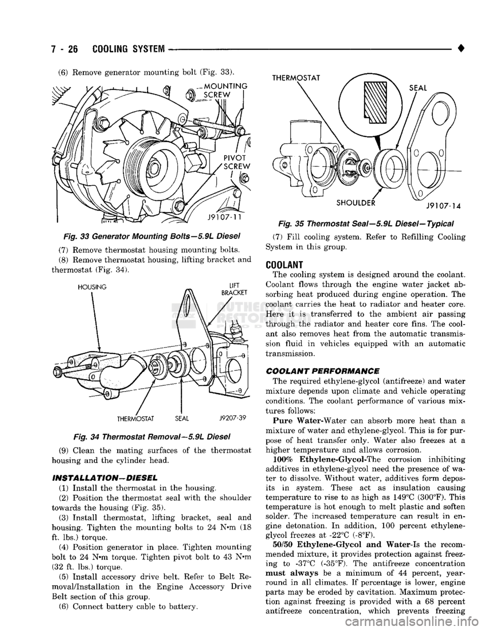
Fig. 33 Generator
Mounting
Bolts—5.9L
Diesel (7) Remove thermostat housing mounting bolts.
(8) Remove thermostat housing, lifting bracket and
thermostat (Fig. 34).
Fig.
34 Thermostat Removal—5.9L
Diesel
(9) Clean the mating surfaces of the thermostat
housing and the cylinder head.
INSTALLA TION—DIESEL (1) Install the thermostat in the housing.
(2) Position the thermostat seal with the shoulder
towards the housing (Fig. 35).
(3) Install thermostat, lifting bracket, seal and
housing. Tighten the mounting bolts to 24 N°m (18 ft. lbs.) torque. (4) Position generator in place. Tighten mounting
bolt to 24 N*m torque. Tighten pivot bolt to 43 N*m (32 ft. lbs.) torque.
(5) Install accessory drive belt. Refer to Belt Re
moval/Installation in the Engine Accessory Drive
Belt section of this group.
(6) Connect battery cable to battery. •
Fig.
35 Thermostat Seai—5.9L Diesel—Typical (7) Fill cooling system. Refer to Refilling Cooling
System in this group.
COOLANT
The cooling system is designed around the coolant.
Coolant flows through the engine water jacket ab sorbing heat produced during engine operation. The
coolant carries the heat to radiator and heater core.
Here it is transferred to the ambient air passing
through the radiator and heater core fins. The cool ant also removes heat from the automatic transmission fluid in vehicles equipped with an automatic
transmission.
COOLANT PERFORMANCE The required ethylene-glycol (antifreeze) and water
mixture depends upon climate and vehicle operating conditions. The coolant performance of various mix
tures follows:
Pure Water-Water can absorb more heat than a
mixture of water and ethylene-glycol. This is for pur
pose of heat transfer only. Water also freezes at a higher temperature and allows corrosion.
100%
Ethylene-Glycol-The corrosion inhibiting
additives in ethylene-glycol need the presence of wa
ter to dissolve. Without water, additives form depos its in system. These act as insulation causing
temperature to rise to as high as 149°C (300°F). This
temperature is hot enough to melt plastic and soften solder. The increased temperature can result in en
gine detonation. In addition, 100 percent ethylene-
glycol freezes at -22°C (-8°F). 50/50 Ethylene-Glycol and Water-Is the recom
mended mixture, it provides protection against freez
ing to -37°C (-35°F). The antifreeze concentration
must always be a minimum of 44 percent, year-
round in all climates. If percentage is lower, engine
parts may be eroded by cavitation. Maximum protec
tion against freezing is provided with a 68 percent antifreeze concentration, which prevents freezing (6) Remove generator mounting bolt (Fig. 33).
Page 304 of 1502
•
COOLING
SYSTEM
7 - 33 The radiator supplies sufficient heat transfer to
cool the engine and automatic transmission (if equipped).
RADIATOR COOLANT FLOW CHECK
Use the following procedure to determine if coolant
is flowing through the cooling system.
(1) Idle engine until operating temperature is
reached. If the upper radiator hose is warm to the
touch, the thermostat is opening and coolant is flow ing to the radiator.
WARNING:
HOT,
PRESSURIZED COOLANT
CAN
CAUSE
INJURY
BY
SCALDING. USING
A
RAG
TO
COVER
THE
RADIATOR
PRESSURE
CAP,
OPEN RADIATOR
CAP
SLOWLY
TO THE
FIRST STOP.
THIS
WILL
ALLOW
ANY
BUILT-UP
PRESSURE
TO
VENT
TO
THE
RESERVE/OVERFLOW TANK. AFTER
PRESSURE
BUILD-UP
HAS
BEEN RELEASED,
RE
MOVE
CAP
FROM FILLER NECK.
(2) Drain a small amount of coolant from the radi
ator until the ends of the radiator tubes are visible
through the filler neck. Idle the engine at normal op
erating temperature. If coolant is flowing past the
exposed tubes, the coolant is circulating.
RADIATOR REMOVAL-EXCEPT DIESEL
(1) Disconnect negative battery cable from battery.
WARNING;
DO NOT
REMOVE
THE
CYLINDER BLOCK DRAIN PLUGS
OR
LOOSEN
THE
RADIATOR
DRAINCOCK
WITH
THE
SYSTEM
HOT AND
UNDER
PRESSURE.
SERIOUS BURNS FROM COOLANT
CAN OCCUR.
(2) Drain the cooling system. Refer to Draining
Cooling System.
(3) Disconnect throttle cable from clip at radiator
fan shroud. (4) Remove hose clamps and hoses from radiator.
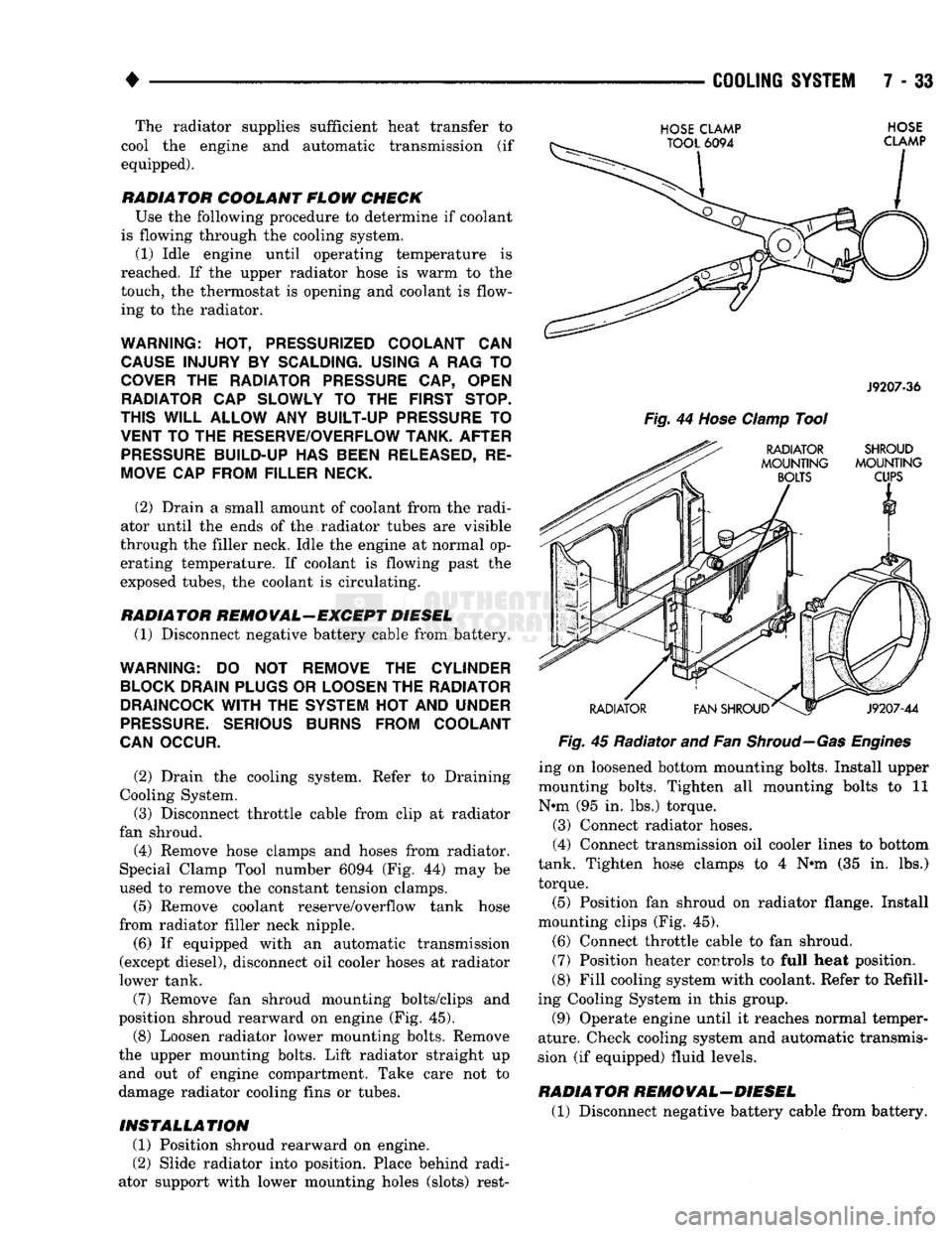
Special Clamp Tool number 6094 (Fig. 44) may be
used to remove the constant tension clamps.
(5) Remove coolant reserve/overflow tank hose
from radiator filler neck nipple.
(6) If equipped with an automatic transmission
(except diesel), disconnect oil cooler hoses at radiator
lower tank.
(7) Remove fan shroud mounting bolts/clips and
position shroud rearward on engine (Fig. 45). (8) Loosen radiator lower mounting bolts. Remove
the upper mounting bolts. Lift radiator straight up and out of engine compartment. Take care not to
damage radiator cooling fins or tubes.
INSTALLATION
(1) Position shroud rearward on engine.
(2) Slide radiator into position. Place behind radi
ator support with lower mounting holes (slots) rest-
HOSE
CLAMP
TOOL
6094
HOSE
CLAMP
J9207-36
Fig.
44
Hose
Clamp
Tool
RADIATOR SHROUD
MOUNTING MOUNTING
BOLTS
CUPS
RADIATOR
V1
FAN SHROUD^
J9207-44
Fig.
45 Radiator and Fan
Shroud—Gas Engines
ing on loosened bottom mounting bolts. Install upper
mounting bolts. Tighten all mounting bolts to 11
N*m (95 in. lbs.) torque.
(3) Connect radiator hoses.
(4) Connect transmission oil cooler lines to bottom
tank. Tighten hose clamps to 4 N#m (35 in. lbs.)
torque.
(5) Position fan shroud on radiator flange. Install
mounting clips (Fig. 45).
(6) Connect throttle cable to fan shroud.
(7) Position heater controls to full heat position.
(8) Fill cooling system with coolant. Refer to Refill
ing Cooling System in this group.
(9) Operate engine until it reaches normal temper
ature. Check cooling system and automatic transmis
sion (if equipped) fluid levels.
RADIATOR REMOVAL-DIESEL
(1) Disconnect negative battery cable from battery.
Page 306 of 1502
•
COOLING
SYSTEM
7 - 35
HOSE
CLAMP TOOL
6094
HOSE
CLAMP
J9207-36
Fig.
48
Hose
damp Tool
TRANSMISSION
OIL
COOLER—EXCEPT DIESEL
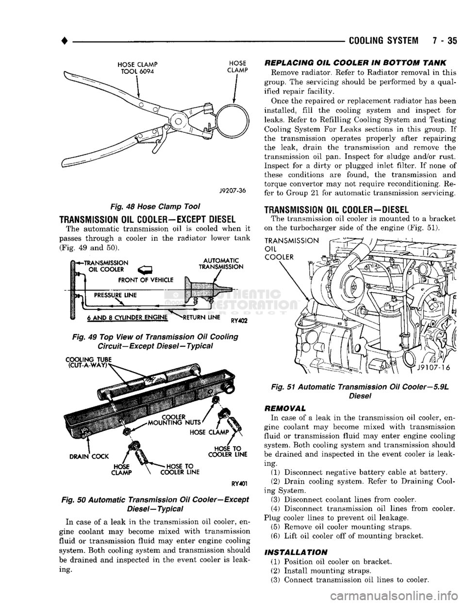
The automatic transmission oil is cooled when it
passes through a cooler in the radiator lower tank (Fig. 49 and 50).
h*-TRANSMISSION
- OIL
COOLER
FRONT
OF
VEHICLE
AUTOMATIC
TRANSMISSION
PRESSURE
LINE
6 AND
8
CYLINDER ENGINE
RETURN
LINE
RY402
Fig.
49 Top View of
Transmission
Oil
Cooling
Circuit—Except Diesel—Typical
COOLING
TUBE (CUT-A-WAY)
DRAIN
COCK
HOSE
CLAMP
HOSE
TO
COOLER
LINE
HOSE
TO
COOLER
LINE
RY401
Fig.
50 Automatic
Transmission
Oil Cooler—Except
Diesel—
Typical
In case of a leak in the transmission oil cooler, en
gine coolant may become mixed with transmission
fluid or transmission fluid may enter engine cooling system. Both cooling system and transmission should
be drained and inspected in the event cooler is leak ing.
REPLACING
OIL
COOLER
IN
BOTTOM
TANK
Remove radiator. Refer to Radiator removal in this
group. The servicing should be performed by a qual
ified repair facility.
Once the repaired or replacement radiator has been
installed, fill the cooling system and inspect for
leaks.
Refer to Refilling Cooling System and Testing Cooling System For Leaks sections in this group. If
the transmission operates properly after repairing
the leak, drain the transmission and remove the
transmission oil pan. Inspect for sludge and/or rust. Inspect for a dirty or plugged inlet filter. If none of
these conditions are found, the transmission and
torque convertor may not require reconditioning. Re
fer to Group 21 for automatic transmission servicing.
1RANSMISSI0N
OIL
COOLER-DIESEL
The transmission oil cooler is mounted to a bracket
on the turbocharger side of the engine (Fig. 51).
TRANSMISSION
OIL
COOLER
Fig.
51 Automatic
Transmission
Oil Cooler—5.9L
Diesel
REMOVAL
In case of a leak in the transmission oil cooler, en
gine coolant may become mixed with transmission
fluid or transmission fluid may enter engine cooling system. Both cooling system and transmission should
be drained and inspected in the event cooler is leak ing. (1) Disconnect negative battery cable at battery.
(2) Drain cooling system. Refer to Draining Cool
ing System. (3) Disconnect coolant lines from cooler.
(4) Disconnect transmission oil lines from cooler.
Plug cooler lines to prevent oil leakage. (5) Remove oil cooler mounting straps.
(6) Lift oil cooler off of mounting bracket.
INSTALLATION
(1) Position oil cooler on bracket.
(2) Install mounting straps.
(3) Connect transmission oil lines to cooler.
Page 898 of 1502
•
FUEL SYSTEM
14-79
OVERDRIVE/OVERRIDE SWITCH-PCM
INPUT
The overdrive/override switch is not used with
manual transmissions. On vehicles equipped with overdrive, the PCM reg
ulates the 3-4 overdrive upshift and downshift
through the overdrive solenoid. An override switch is located on the instrument panel. The overdrive/override switch is a momentary con
tact switch. The switch contacts are normally open. When the switch is activated, the PCM will receive a ground signal. The transmission will not enter over
drive when the operator presses the override switch.
The transmission downshifts if the operator presses
the override switch while in overdrive.
COOLANT TEMPERATURE SENSOR The coolant temperature sensor is not used with
manual transmissions.
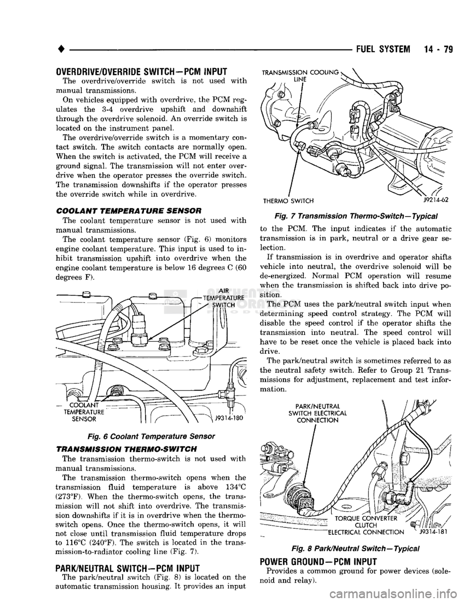
The coolant temperature sensor (Fig. 6) monitors
engine coolant temperature. This input is used to in
hibit transmission upshift into overdrive when the
engine coolant temperature is below 16 degrees C (60
degrees F).
Fig.
6 Coolant
Temperature
Sensor
TRANSMISSION THERMO-SWITCH The transmission thermo-switch is not used with
manual transmissions.
The transmission thermo-switch opens when the
transmission fluid temperature is above 134°C (273°F). When the thermo-switch opens, the trans
mission will not shift into overdrive. The transmis sion downshifts if it is in overdrive when the thermo-
switch opens. Once the thermo-switch opens, it will
not close until transmission fluid temperature drops
to 116°C (240°F). The switch is located in the trans mission-to-radiator cooling line (Fig. 7).
PARK/NEUTRAL SWITCH-PCM
INPUT
The park/neutral switch (Fig. 8) is located on the
automatic transmission housing. It provides an input
THERMO SWITCH
J9214-62
Fig.
7
Transmission
Thermo-Switch—Typical to the PCM. The input indicates if the automatic
transmission is in park, neutral or a drive gear se lection.
If transmission is in overdrive and operator shifts
vehicle into neutral, the overdrive solenoid will be de-energized. Normal PCM operation will resume
when the transmission is shifted back into drive po sition.
The PCM uses the park/neutral switch input when
determining speed control strategy. The PCM will
disable the speed control if the operator shifts the
transmission into neutral. The speed control will
have to be reset once the vehicle is placed back into drive.
The park/neutral switch is sometimes referred to as
the neutral safety switch. Refer to Group 21 Trans missions for adjustment, replacement and test infor
mation.
Fig.
8 Park/Neutral Switch—Typical
POWER
GROUND-PCM
INPUT
Provides a common ground for power devices (sole
noid and relay).
Page 906 of 1502
•
FUEL
SYSTEM
14 - 87
ENGINE
WARM-UP
• The PCM may start the air intake heater post-heat
cycle depending on intake air temperature. If manifold air temperature was at or below 15°C (59°F) when the
ignition switch was turned on, the cycle is started.
• If intake manifold air temperature is below 32°C
(90°F),
the KSB solenoid will be energized through
the air temperature switch. The solenoid remains en ergized until the air temperature switch opens. The
switch opens when intake manifold air temperature
is above 32°C (90°F).
• If the coolant temperature is below 16°C (60° F),
the transmission will not be allowed to enter over drive (automatic transmission).
• The PCM will turn on the water-in-fuel lamp if a signal is received from the water-in-fuel sensor.
CRUISE
OR
IDLE
• The PCM monitors intake manifold air tempera
ture through the charge temperature sensor input. • If intake manifold air temperature is below 32°C
(90°F),
the KSB solenoid will be energized through
the air temperature switch. The solenoid remains en ergized until the air temperature switch opens. The switch opens when intake manifold air temperature
is above 32°C (90°F).
• The air intake heater post-heat cycle will be com
pleted, if it is not already over.
• The vehicle speed sensor, engine speed sensor and
throttle position sensor inputs are used to control
transmission overdrive operation.
• If the coolant temperature is below 16° C (60° F),
the transmission will not be allowed to enter over drive (automatic transmission).
• If the transmission thermo-switch is open, the
transmission will not be allowed to enter into over
drive (automatic transmission). If the switch opens
when the vehicle is in overdrive, the transmission
will be downshifted. The transmission thermo-switch opens at 134°C (273°F).
• The thermo-switch will close once the transmission
fluid temperature drops to 116°C (240°F). • The PCM will turn on the water-in-fuel lamp if a signal is received from the water-in-fuel sensor.
ACCELERATION
• The vehicle speed sensor, engine speed sensor and
throttle position sensor inputs are used to control
transmission overdrive operation.
• If the coolant temperature is below 16° C (60° F),
the transmission will not be allowed to enter over
drive (automatic transmission).
• If intake manifold air temperature is below 32°C
(90°F),
the KSB solenoid will be energized through
the air temperature switch. The solenoid remains en ergized until the air temperature switch opens. The
switch opens when intake manifold air temperature
is above 32°C (90°F). • If the transmission thermo-switch is open, the
transmission will not be allowed to enter into over
drive (automatic transmission). If the switch opens
when the vehicle is in overdrive, the transmission
will be downshifted. The transmission thermo-switch opens at 134°C (273°F). The thermo-switch will close
once the transmission fluid temperature drops to 116°C (240°F).
• The PCM will turn on the water-in-fuel lamp if a
signal is received from the water-in-fuel sensor.
• If the speed control system resume/accelerate func
tion is being used, the PCM will only allow the vehi
cle to accelerate at a predetermined rate. If a speed
control has been set and the resume/accelerate but
ton is momentarily pushed in, the PCM will increase
vehicle speed by two miles per hour.
• If the brakes are applied, the PCM will disable the
speed control.
DECELERATION
• The vehicle speed sensor, engine speed sensor and
throttle position sensor inputs are used to control
transmission overdrive operation.
• If the coolant temperature is below 16° C (60° F),
the transmission will not be allowed to enter over drive (automatic transmission).
• If the transmission thermo-switch is open, the trans
mission will not be allowed to enter into overdrive (au
tomatic transmission). If the switch opens when the
vehicle is in overdrive, the transmission will be down shifted. The transmission thermo-switch opens at 134°C (273°F). The thermo-switch will close once the transmis
sion fluid temperature drops to 116°C (240°F).
• The PCM will turn on the water-in-fuel lamp if a
signal is received from the water-in-fuel sensor.
• If intake manifold air temperature is below 32°C
(90°F),
the KSB solenoid will be energized through
the air temperature switch. The solenoid remains en ergized until the air temperature switch opens. The
switch opens when intake manifold air temperature
is above 32°C (90°F).
• If the speed control system coast/set function is be
ing used, the PCM will only allow the vehicle to de celerate at a predetermined rate. If the coast/set
switch is pushed while the system is operating, the
PCM will set speed control to the rate the vehicle is
traveling at when the switch is released. • If the brakes are applied, the PCM will disable the speed control.
IGNITION SWITCH
OFF
• When the ignition switch is turned to the off posi
tion, the PCM still receives battery voltage through
the battery input. Battery voltage is needed to keep
PCM memory alive. The PCM memory stores diag nostic trouble code (DTC) messages and the mini
mum TPS value from the previous key-on.