1993 DODGE TRUCK brake light
[x] Cancel search: brake lightPage 7 of 1502
2 INTRODUCTION
•
MFD
BY
GAWR
FRONT
GAWR REAR
CHRYSLER
CORPORATION
DATE
OF MFR
GVWR
WITH
TIRES
WITH
TIRES
RIMS
AT
RIMS
AT
PSI
COLD
PSI
COLD
THIS
VEHICLE CONFORMS
TO
ALL APPLICABLE FEDERAL MOTOR VEHICLE SAFETY
STANDARDS
IN
EFFECT ON
THE
DATE
OF
MANUFACTURE SHOWN ABOVE.
SINGLE
DUAL
MDH:
BAR
CODE
VEHICLE MADE
IN
4648503
J9HN-25
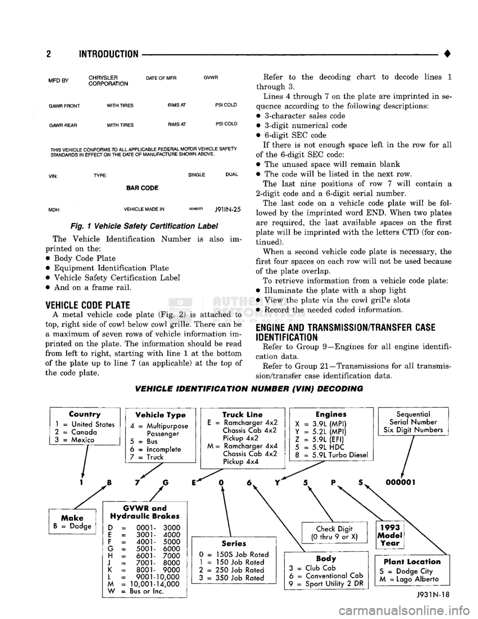
Fig. 1 Vehicle Safety Certification Label
The Vehicle Identification Number is also im
printed on the:
• Body Code Plate
• Equipment Identification Plate
• Vehicle Safety Certification Label
• And on a frame rail.
VEHICLE CODE PLATE
A metal vehicle code plate (Fig. 2) is attached to
top,
right side of cowl below cowl grille. There can be a maximum of seven rows of vehicle information im
printed on the plate. The information should be read
from left to right, starting with line 1 at the bottom
of the plate up to line 7 (as applicable) at the top of
the code plate. Refer to the decoding chart to decode lines 1
through 3.
Lines 4 through 7 on the plate are imprinted in se
quence according to the following descriptions:
• 3-character sales code • 3-digit numerical code
• 6-digit SEC code If there is not enough space left in the row for all
of the 6-digit SEC code:
• The unused space will remain blank
• The code will be listed in the next row.
The last nine positions of row 7 will contain a
2-digit code and a 6-digit serial number.
The last code on a vehicle code plate will be fol
lowed by the imprinted word END. When two plates
are required, the last available spaces on the first
plate will be imprinted with the letters CTD (for con tinued).
When a second vehicle code plate is necessary, the
first four spaces on each row will not be used because of the plate overlap.
To retrieve information from a vehicle code plate:
• Illuminate the plate with a shop light
• View the plate via the cowl grille slots
• Record the needed coded information.
ENGINE AND TRANSMISSION/TRANSFER CASE
IDENTIFICATION
Refer to Group 9—Engines for all engine identifi
cation data. Refer to Group 21—Transmissions for all transmis
sion/transfer case identification data.
VEHICLE IDENTIFICATION NUMBER (VIN) DECODING
Country
1
=
United States
2
=
Canada
3
=
Mexico Vehicle Type
4
=
Multipurpose
Passenger
5
=
Bus
6
=
Incomplete
7
=
Truck
GVWR
and
Hydraulic Brakes
0001 3001
4001
5001 6001
7001 8001
9001
10,001
Bus
or I
3000
4000
5000 6000
7000 8000
9000
10,000
14,000
nc.
Truck Line
E
=
Ramcharger
4x2
Chassis
Cab
4x2
Pickup
4x2
M
=
Ramcharger
4x4
Chassis
Cab
4x2
Pickup
4x4
Engines
X
=
3.9L
(MPI)
Y = 5.2L
(MPI)
Z
=
5.9L
(EFI)
5
=
5.9L HDC
8
=
5.9L Turbo Diesel Sequential
Serial Number
Six
Digit Numbers
Series
0 =
150S Job Rated
1
= 150
Job Rated
2
= 250
Job Rated
3
= 350
Job Rated
Body
3
=
Club Cab 6
=
Conventional Cab
9
=
Sport
Utility
2 DR
Plant Location
S
=
Dodge City
M
=
Lago
Alberto J931N-18
Page 15 of 1502
10 INTRODUCTION
•
INTERNATIONAL CONTROL AND DISPLAY SYMBOLS
ID
HIGH
BEAM P
FOG UGHTS -&
HEADLIGHTS,
PARKING UGHTS, PANEL UGHTS TURN SIGNAL A
HAZARD WARNING WINDSHIELD
WASHER
WINDSHIELD WIPER WINDSHIELD WIPER
AND WASHER
AND DEFROSTING *
VENTILATING
FAN 8
M f
REAR
WINDOW DEFOGGER
sp
REARWINLX)W WIPER
CD
l
m
REAR
WINDOW WASHER FUEL ENGINE COOLANT
TEMPERATURE BATTERY CHARGING
CONDITION ENGINE OIL
SEAT
BELT
(©) (®) ky
11 J
LIGHTER
BRAKE
FAILURE
PARKING
BRAKE
FRONT HOOD
REAR
HOOD
(TRUNK)
HORN
11 J
LIGHTER
93IN-9
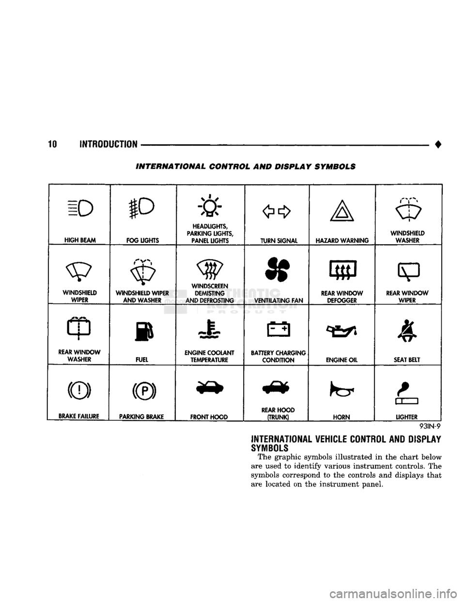
INTERNATIONAL VEHICLE CONTROL AND DISPLAY
SYMBOLS
The graphic symbols illustrated in the chart below
are used to identify various instrument controls. The
symbols correspond to the controls and displays that are located on the instrument panel.
Page 21 of 1502
0 - 2
LUBRICATION
AND
MAINTENANCE
• Commercial service
When a vehicle is continuously subjected to severe
driving conditions, lubricate:
• Body components
• All the driveline coupling joints
• Steering linkage More often than normal driving conditions
DUSTY
AREAS
With this type of severe driving condition, special
care should be given to the:
• Engine air cleaner filter
• PCV filter
• Crankcase ventilation system
• Brake booster control valve air filter. Verify that the filters and the associated compo
nents are clean. Also verify that they are functioning
effectively. This will minimize the amount of abra sive particles that enter the engine.
OFF-ROAD
(4WD)
OPERATION
After off-road (4WD) operation, inspect the under
side of the vehicle. Inspect the:
• Tires
• Body structure
• Steering components
• Suspension components • Exhaust system
• Threaded fasteners
HARSH
SURFACE ENVIRONMENTS
After extended operation in harsh environments,
the brake drums, brake linings, and rear wheel bear ings should be inspected and cleaned. This will pre
vent wear and erratic brake action.
ROUTINE MAINTENANCE
The following routine maintenance is recommended
on a monthly basis: TIRES—Inspect the tires for unusual wear/damage.
Determine if the inflation pressure is adequate for
the vehicle load. BATTERY—Inspect and clean the terminals.
Tighten the terminals if necessary. FLUIDS—Determine if the component fluid levels
are acceptable. Add fluid, if necessary. LIGHTS/ELECTRICAL—Test all the electrical sys
tems in the vehicle for proper operation. It is also recommended that the engine oil and the
washer fluid level be determined at each fuel fill-up.
VEHICLE
NOISE CONTROL
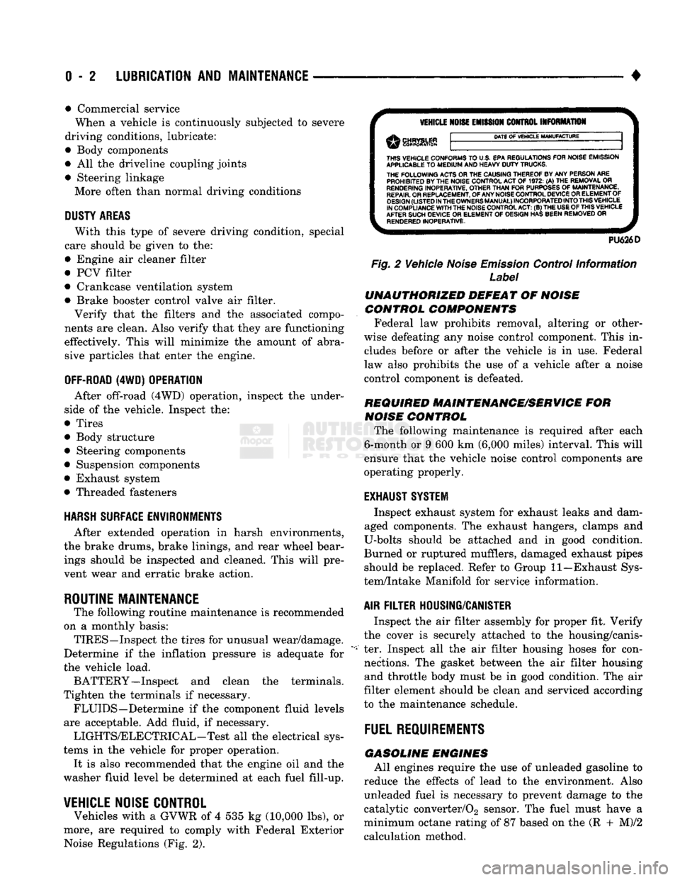
Vehicles with a GVWR of 4 535 kg (10,000 lbs), or
more, are required to comply with Federal Exterior Noise Regulations (Fig. 2).
VEHICLE
NOISE
EMISSION
CONTROL INFORMATION
DATE
OF
VEHICLE
MANUFACTURE
THIS
VEHICLE CONFORMS
TO
U.S. EPA REGULATIONS FOR NOISE EMISSION
APPLICABLE
TO
MEDIUM
AND HEAVY
DUTY
TRUCKS. THE
FOLLOWING
ACTS OR THE CAUSING THEREOF BY ANY PERSON ARE PROHIBITED BY THE NOISE CONTROL ACT
OF 1972. (A) THE
REMOVAL
OR
RENDERING
INOPERATIVE, OTHER
THAN
FOR
PURPOSES
OF
MAINTENANCE,
REPAIR.
OR REPLACEMENT, OF ANY NOISE CONTROL DEVICE OR ELEMENT OF
DESIGN
(LISTED
IN
THE
OWNERS
MANUAL)
INCORPORATED
INTO
THIS
VEHICLE
IN COMPLIANCE
WITH
THE NOISE CONTROL
ACT:
(B) THE
USE
OF
THIS
VEHICLE
AFTER SUCH DEVICE
OR
ELEMENT
OF
DESIGN HAS BEEN REMOVED
OR
RENDERED
INOPERATIVE.
PU626D
Fig.
2 Vehicle
Noise
Emission
Control Information
Label
UNAUTHORIZED
DEFEAT
OF
NOISE
CONTROL COMPONENTS
Federal law prohibits removal, altering or other
wise defeating any noise control component. This in
cludes before or after the vehicle is in use. Federal
law also prohibits the use of a vehicle after a noise
control component is defeated.
REQUIRED MAINTENANCE/SERVICE
FOR
NOISE
CONTROL
The following maintenance is required after each
6-month or 9 600 km (6,000 miles) interval. This will
ensure that the vehicle noise control components are
operating properly.
EXHAUST SYSTEM
Inspect exhaust system for exhaust leaks and dam
aged components. The exhaust hangers, clamps and
U-bolts should be attached and in good condition.
Burned or ruptured mufflers, damaged exhaust pipes should be replaced. Refer to Group 11—Exhaust Sys
tem/Intake Manifold for service information.
AIR
FILTER
HOUSING/CANISTER
Inspect the air filter assembly for proper fit. Verify
the cover is securely attached to the housing/canis
ter. Inspect all the air filter housing hoses for con nections. The gasket between the air filter housing and throttle body must be in good condition. The air
filter element should be clean and serviced according
to the maintenance schedule.
FUEL
REQUIREMENTS
GASOLINE
ENGINES
All engines require the use of unleaded gasoline to
reduce the effects of lead to the environment. Also unleaded fuel is necessary to prevent damage to the
catalytic converter/02 sensor. The fuel must have a
minimum octane rating of 87 based on the (R + M)/2
calculation method.
Page 26 of 1502

CHASSIS LUBRICATION
For light
duty
cycle
vehicles
GVW resting
of
3 855 Kg (8,500 lbs ) and
below.
Component
Truck Models
Fittings
Service Interval Lubricant
Center Link
AD1
AD2
AD
4
2
36
000
km
(22,500
miles)
or 2
years Multi-purpose grease
-
NGLI
grade
2
EP
(Multi-Mileage Lubricant)
Drag
Link
Bali
joints
AW1 AW 2
AW
8
2
12
000
km
(7,500
miles)
or 6
months Multi-purpose grease
-
NGLI
grade
2
EP
(Multi-Mileage Lubricant)
Gearshift
Mechanism
Overdrive
4
AD1
1
36
000
km
(22,500
miles)
or 2
years Multi-purpose grease
-
NGLI
grade
2
EP
(Multi-Purpose Lubricant)
Parking Brake Ratio
Lever
Pivot
AD1 AD
2 AD 4
AW1 AW 8
—
36
000
km
(22,500
miles)
or 2
years
Multi-purpose grease
-
NGLI
grade
2
EP
(Multi-Purpose Lubricant)
Propeller Shaft
U-joint
AW1
AW2
AW 8
3
(1
Piece
rear
P/shaft)
12
000
km
(7,500
miles)
or 6
months
Multi-purpose grease
-
NGLI
grade
2
EP
(Multi-Purpose Lubricant)
Propeller Shaft
Slip
Spline
AD1 AD
2
(2
piece P/shaft)
1
36
000
km
(22,500
miles)
or 2
years. For severe
service,
every
4
800
km
(3,000
miles)
or 3
months. Daily,
if
vehicle is operated in
water
Multi-purpose grease
-
NGLI
grade
2
EP
(Multi-Purpose Lubricant)
Suspension
Ball Joints
AD1 AD
2
4
36
000
km
(22,500
miles) or 2 years
—
every
engine
oil change
for
off-highway operation Multi-purpose grease
-
NGLI
grade
2
EP
(Multi-Mileage Lubricant)
Tie Rod Ball Joints
AD1
AD2
AD4
AW1 AW
2
AW8 4
2
36
000
km
(22,500
miles)
or 2
years
12
000
km
(7,500
miles)
or 6
months. Daily,
if
vehicle is operated in
water
Multi-purpose grease
-
NGLI
grade
2
EP
(Multi-Mileage Lubricant)
NP-241 Transfer
Case
Shift
Lever Pivot
AW1
AW2
AW8
—
As
Required
Multi-purpose grease
-
NGLI
grade
2
EP
(Multi-Purpose Lubricant)
Wheel
Stop
AD1 AD
2
AD4
—
36
000
km
(22,500
miles)
or
as
required
Wax Type Lubricant
Constant
Velocity Joint
(Front
P/shaft)
AW1
AW2
AW8 1
12
000
km
(7,500
miles) Multi-purpose grease
-
NGLI
grade
2
EP
(Multi-Purpose Lubricant)
>
J9000-59
>
Page 28 of 1502
•
LUBRICATION AND MAINTENANCE
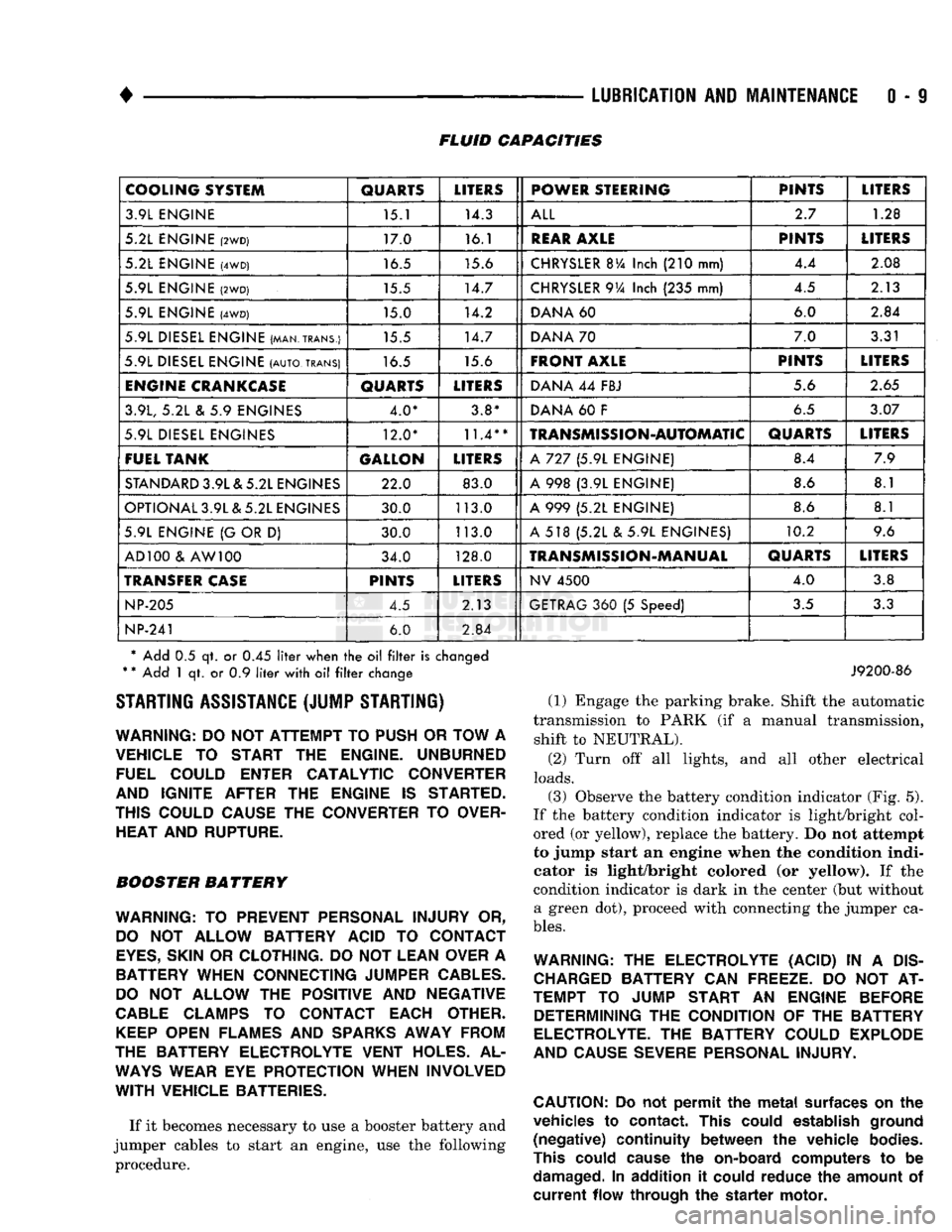
0 - 9 FLUID CAPACITIES
COOLING SYSTEM
QUARTS
LITERS
POWER STEERING PINTS
LITERS
3.9L ENGINE 15.1 14.3
ALL
2.7
1.28
5.2L ENGINE
(2WD)
17.0 16.1
REAR
AXLE
PINTS
LITERS
5.2L ENGINE
(4WD)
16.5 15.6
CHRYSLER
BVa
Inch
(210
mm) 4.4
2.08
5.9L ENGINE
(2WD)
15.5 14.7
CHRYSLER
9Va
Inch
(235
mm) 4.5
2.13
5.9L ENGINE
(4WD)
15.0 14.2
DANA
60 6.0
2.84
5.9L DIESEL ENGINE (MAN.TRANS.) 15.5 14.7
DANA
70 7.0
3.31
5.9L DIESEL ENGINE
(AUTO,
TRANS)
16.5 15.6
FRONT AXLE
PINTS
LITERS
ENGINE
CRANKCASE
QUARTS
LITERS
DANA
44
FBJ 5.6
2.65
3.9L,
5.2L & 5.9
ENGINES 4.0* 3.8*
DANA
60 F
6.5
3.07
5.9L DIESEL ENGINES 12.0*
11.4**
TRANSMISSION-AUTOMATIC
QUARTS
LITERS
FUEL TANK GALLON
LITERS
A
727 (5.9L
ENGINE) 8.4
7.9
STANDARD
3.9L & 5.2L ENGINES 22.0 83.0
A
998 (3.9L
ENGINE) 8.6
8.1
OPTIONAL 3.9L & 5.2L ENGINES 30.0 113.0
A
999 (5.2L
ENGINE) 8.6
8.1
5.9L ENGINE
{G
OR
D)
30.0 113.0
A
518 (5.2L & 5.9L
ENGINES) 10.2
9.6
AD 100
&
AW 100 34.0 128.0
TRANSMISSION-MANUAL
QUARTS
LITERS
TRANSFER
CASE
PINTS
LITERS
NV
4500
4.0
3.8
NP-205
4.5 2.13
GETRAG
360 (5
Speed)
3.5
3.3
NP-241
6.0
2.84
* Add
0.5 qt. or 0.45
liter
when
the oil filter
is
changed
*
*
Add
1 qt. or 0.9
liter
with
oil filter
change STARTING ASSISTANCE (JUMP STARTING)
WARNING:
DO NOT
ATTEMPT
TO
PUSH
OR
TOW
A
VEHICLE
TO
START
THE
ENGINE. UNBURNED FUEL COULD ENTER CATALYTIC CONVERTER
AND IGNITE AFTER
THE
ENGINE
IS
STARTED.
THIS COULD CAUSE
THE
CONVERTER
TO
OVER HEAT AND RUPTURE.
BOOSTER BATTERY
WARNING:
TO
PREVENT PERSONAL INJURY
OR,
DO
NOT
ALLOW BATTERY ACID
TO
CONTACT
EYES,
SKIN
OR
CLOTHING.
DO NOT
LEAN OVER
A
BATTERY WHEN CONNECTING JUMPER
CABLES.
DO
NOT
ALLOW
THE
POSITIVE
AND
NEGATIVE
CABLE
CLAMPS
TO
CONTACT EACH OTHER.
KEEP
OPEN FLAMES
AND
SPARKS
AWAY FROM
THE BATTERY ELECTROLYTE VENT HOLES.
AL
WAYS
WEAR
EYE
PROTECTION WHEN INVOLVED
WITH
VEHICLE BATTERIES.
If it becomes necessary to use a booster battery and
jumper cables to start an engine, use the following procedure.
J9200-86
(1) Engage the parking brake. Shift the automatic
transmission to PARK (if a manual transmission, shift to NEUTRAL).
(2) Turn off all lights, and all other electrical
loads.
(3)
Observe the battery condition indicator (Fig. 5).
If the battery condition indicator is light/bright col
ored (or yellow), replace the battery. Do not attempt
to jump start an engine when the condition indi
cator is light/bright colored (or yellow). If the
condition indicator is dark in the center (but without a green dot), proceed with connecting the jumper ca
bles.
WARNING:
THE
ELECTROLYTE (ACID)
IN A
DIS
CHARGED
BATTERY
CAN
FREEZE.
DO NOT AT
TEMPT
TO
JUMP START
AN
ENGINE BEFORE DETERMINING
THE
CONDITION
OF THE
BATTERY
ELECTROLYTE.
THE
BATTERY COULD EXPLODE
AND CAUSE SEVERE PERSONAL INJURY.
CAUTION:
Do not
permit
the
metal
surfaces
on the
vehicles
to
contact.
This
could
establish
ground
(negative)
continuity
between
the
vehicle
bodies.
This
could
cause
the
on-board
computers
to be
damaged.
In
addition
it
could
reduce
the
amount
of
current
flow
through
the
starter
motor.
Page 41 of 1502
0
- 22
LUBRICATION
AND
MAINTENANCE
DRIVETRAIN
INDEX
page
Axles
25
Clutch
and
Brake Pedal
Bushings
............ 22
Clutch Master Cylinder
22
Drive Shafts
26
page
Front Axle U-Joint
and
Pivot Bearings
......... 26
Transfer
Case
(4WD
Vehicles)
. . ........ 24
Transmissions
. 22
CLUTCH
AND
BRAKE PEDAL
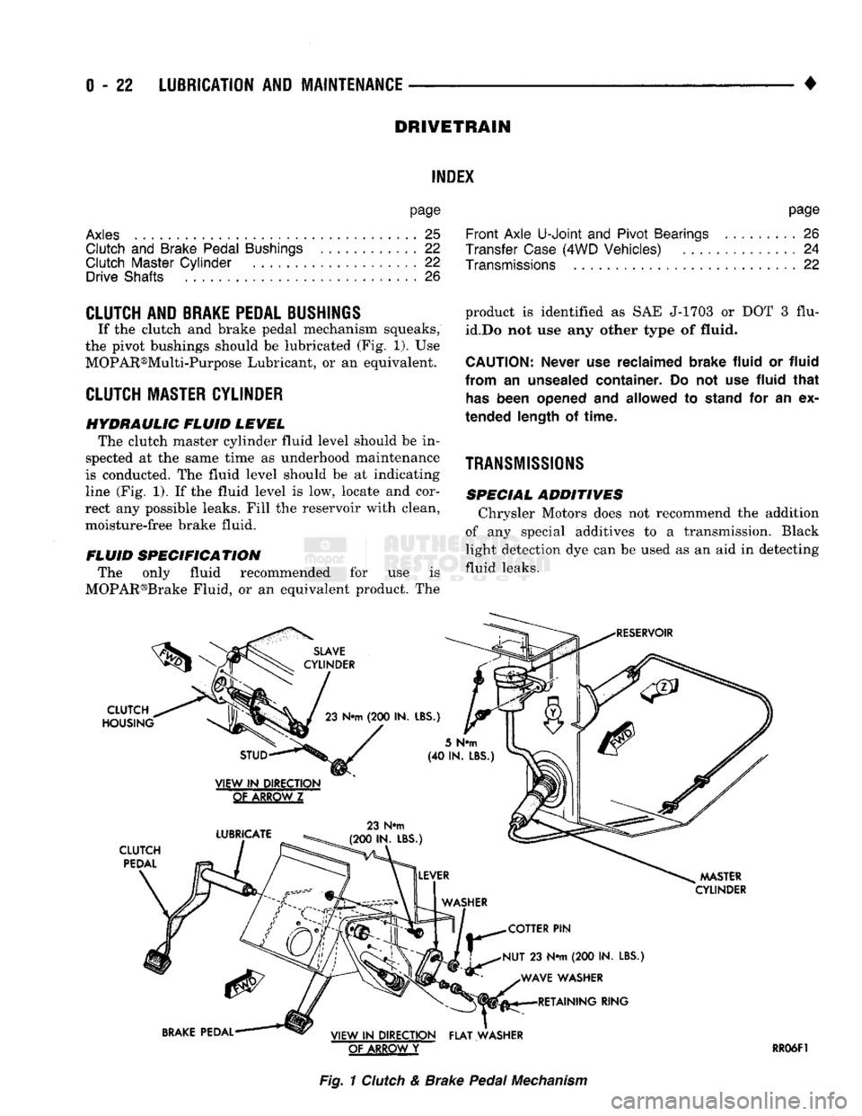
If the clutch and brake pedal mechanism squeaks,
the pivot bushings should be lubricated (Fig. 1). Use
MOPAR®Multi-Purpose Lubricant, or an equivalent.
CLUTCH
MASTER CYLINDER
HYDRAULIC FLUID LEVEL The clutch master cylinder fluid level should be in
spected at the same time as underhood maintenance
is conducted. The fluid level should be at indicating
line (Fig. 1). If the fluid level is low, locate and cor
rect any possible leaks. Fill the reservoir with clean,
moisture-free brake fluid.
FLUID SPECIFICATION The only fluid recommended for use is
MOPAR®Brake Fluid, or an equivalent product. The
SLAVE
CYLINDER
CLUTCH
HOUSING
23
N«m
(200 IN.
LBS.)
product is identified as SAE J-1703 or DOT 3 flu
id.Do not use any other type of
fluid.
CAUTION:
Never
use
reclaimed brake fluid
or
fluid
from
an
unsealed container.
Do not use
fluid that
has
been opened
and
allowed
to
stand
for an ex
tended length
of
time.
TRANSMISSIONS
SPECIAL ADDITIVES Chrysler Motors does not recommend the addition
of any special additives to a transmission. Black
light detection dye can be used as an aid in detecting
fluid leaks.
RESERVOIR
STUD
VIEW
IN
DIRECTION
GtAKBQWZ
LUBRICATE
CLUTCH
PEDAL
23 N#m
(200 IN. LBS.)
5
N«m
(40 IN.
LBS
MASTER
CYLINDER
COTTER
PIN
NUT
23 N*m (200 IN.
LBS.) WAVE WASHER RETAINING RING
BRAKE
PEDAL VIEW
IN
DIRECTION FLAT WASHER
OF ARROW
Y
RR06F1
Fig.
1
Clutch
& Brake
Pedal
Mechanism
Page 42 of 1502
•
LUBRICATION
AND
MAINTENANCE
0 - 23 GEAR SHIFTER BOOTS
Inspect the shifter boots periodically for stone and
heat damage. Replace, if necessary.
SEVERE DRIVING CONDITIONS The interval between the transmission drain and
refill maintenance should be decreased to:
• NV4500 manual transmission—every 29 000 km (18,000 miles)
• Automatic transmission—every 19 000 km (12,000
miles)
A severe driving condition includes:
• Extended operation with heavy cargo loads
• Driving in deep mud or snow
• Off-road operation (4WD)
• Trailer towing
• Operation as a commercial vehicle
• Snow plowing
MANUAL TRANSMISSIONS
INSPECTION/LUBE
OIL
LEVEL
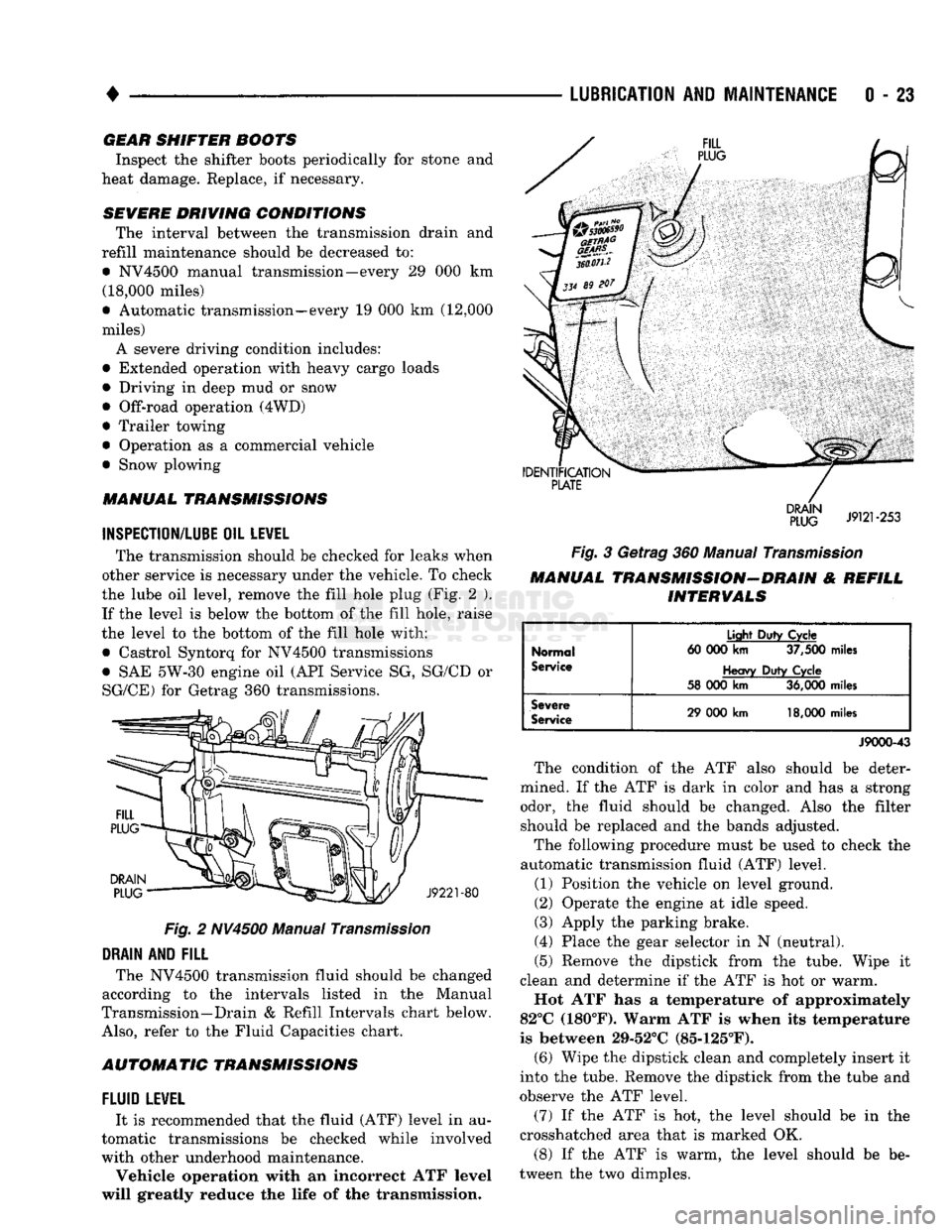
The transmission should be checked for leaks when
other service is necessary under the vehicle. To check
the lube oil level, remove the fill hole plug (Fig. 2 ). If the level is below the bottom of the fill hole, raise
the level to the bottom of the fill hole with:
• Castrol Syntorq for NV4500 transmissions
• SAE 5W-30 engine oil (API Service SG, SG/CD or
SG/CE) for Getrag 360 transmissions.
Fig.
2 NV4500 Manual
Transmission
DRAIN
AND
FILL
The NV4500 transmission fluid should be changed
according to the intervals listed in the Manual
Transmission—Drain & Refill Intervals chart below.
Also,
refer to the Fluid Capacities chart.
AUTOMATIC TRANSMISSIONS
FLUID
LEWEL
It is recommended that the fluid (ATF) level in au
tomatic transmissions be checked while involved
with other underhood maintenance.
Vehicle operation with an incorrect ATF level
will greatly reduce the life of the transmission.
Fig.
3 Getrag 360 Manual
Transmission
MANUAL TRANSMISSION-DRAIN & REFILL INTERVALS
Normal
Service
Light
Duty
Cycle
60 000
km
37,500
miles
Heavy
Duty
Cycle
58 000
km
36,000
miles
Severe
Service
29 000
km
18,000
miles
J9000-43
The condition of the ATF also should be deter
mined. If the ATF is dark in color and has a strong odor, the fluid should be changed. Also the filter should be replaced and the bands adjusted.
The following procedure must be used to check the
automatic transmission fluid (ATF) level.
(1) Position the vehicle on level ground.
(2) Operate the engine at idle speed.
(3) Apply the parking brake.
(4) Place the gear selector in N (neutral).
(5) Remove the dipstick from the tube. Wipe it
clean and determine if the ATF is hot or warm.
Hot ATF has a temperature of approximately
82°C (180°F). Warm ATF is when its temperature
is between 29-52°C (85-125°F). (6) Wipe the dipstick clean and completely insert it
into the tube. Remove the dipstick from the tube and
observe the ATF level.
(7) If the ATF is hot, the level should be in the
crosshatched area that is marked OK.
(8) If the ATF is warm, the level should be be
tween the two dimples.
Page 47 of 1502
0
- 28
LUBRICATION
AND
MAINTENANCE
•
CHASSIS AND BODY
page
Body
Component Mechanisms
32
Front
Suspension
Ball
Joints
28
Front
Wheel Bearings
29
Headlamps
32
Lower
and
Upper Suspension
Arm
Bushings
.... 30
Manual
Steering Gear
28
STEERING
LINKAGE
INSPECTION When
a
vehicle
is
raised
for
maintenance under
the vehicle,
all
steering components should
be
checked.
LUBRICATION SCHEDULE The steering linkage
is
lubricated with
a
chassis
lubricant. However,
it is
recommended that
the
link
age
be
inspected
and
lubricated after each:
•
24 000 km
(15,000 miles) interval
or
every
6
months,
for 2WD
vehicles subject
to the
LIGHT
DUTY CYCLE Maintenance Schedule
•
9 600 km
(6,000 miles) interval
or
every
6
months,
for
2WD
vehicles subject
to the
HEAVY DUTY
CY
CLE Maintenance Schedule
•
12 000 km
(7,500 miles) interval
or
every
6
months,
for 4WD
vehicles subject
to the
LIGHT DUTY CYCLE Maintenance Schedule
•
9 600 km
(6,000 miles) interval
or
every
6
months,
for
4WD
vehicles subject
to the
HEAVY DUTY
CY
CLE Maintenance Schedule.
LUBRICATION (1) Inspect
the
steering linkage
for
looseness
and
excessive wear. (2) Replace,
all
ruptured seals
and
damaged steer
ing linkage components. Damaged seals should
be re
placed
to
prevent leakage
and
contamination
of the
lubricant.
CAUTION:
Use
care
to
prevent lubricant from
con
tacting
the
brake rotors.
(3) Lubricate
the
steering linkage:
• Clean
the
Zerk type lubrication fittings
on the tie-
rod
and
center link ball-stud ends
• Lubricate
the
ball studs with MOPAR®Multi-Mile- age Lubricant
• Wipe
the
excess lubricant from
the
exterior sur
faces
of the
ball joints
page
Power
Brake System
30
Power
Steering System
. . 29
Rear
Wheel Bearings
30
Speedometer Cable
33
Steering Linkage
28
Tires
32
FRONT
SUSPENSION
BALL JOINTS
INSPECTION When
a
vehicle
is
raised
for
lubrication/general
maintenance,
the
ball joints should
be
inspected.
LUBRICATION SCHEDULE The front suspension ball joints
are
lubricated dur
ing manufacture with
a
long-life chassis lubricant.
However,
it is
recommended that
the
ball joints
be
inspected
and the
studs lubricated:
•
At
each
36 000 km
(22,500 miles) interval
or
every
2 years,
for
vehicles subject
to the
LIGHT DUTY
CY
CLE Maintenance Schedule
•
At
each
9 600 km
(6,000 miles) interval
or
every
2
years,
for
vehicles subject
to the
HEAVY DUTY
CY
CLE Maintenance Schedule.
4WD vehicles that
are
frequently driven
off-
road should
be
lubricated
at
every engine
oil
change.
LUBRICATION (1) Inspect
the
front suspension. Examine
the
ball
studs
for
looseness
and
excessive wear. (2) Replace
all
torn ball-stud seals
and
damaged
ball joints. Damaged seals should
be
replaced
to
pre vent leakage
and
contamination.
CAUTION:
Use
care
to
prevent lubricant from
con
tacting
the
brake rotors.
(3) Lubricate
the
ball studs:
• Clean
the
Zerk type lubrication fittings
on the
ball-stud ends
• Lubricate
the
ball studs with MOPAR®Multi-Mile-age Lubricant
• Wipe
the
excess lubricant from
the
exterior sur
faces
of the
ball joints
MANUAL
STEERING
GEAR
LUBRICATION Manual steering gears
are
permanently lubricated
during manufacture. Periodic lubrication
is not
nec
essary.