1993 DODGE TRUCK brake rotor
[x] Cancel search: brake rotorPage 31 of 1502

0 - 12
LUBRICATION
AND
MAINTENANCE
• A vehicle equipped with SAE approved sling-type
towing equipment can be used (Fig. 10). However,
many vehicles are equipped with air dams, spoilers, and/or ground effect panels. In this case a wheel-lift
towing vehicle or a flat-bed hauling vehicle is recom mended (Fig. 10). If a flat bed device is used, the ap
proach angle should not exceed 15 degrees.
GROUND CLEARANCE The lifted wheels of the disabled vehicle should be
a minimum of 10 cm (4 in.) off the ground. Make
sure there is enough clearance at the opposite end.
This is critical when towing over rough terrain. If necessary, the rear ground clearance can be increased by removing the wheels from the lifted end
and then towing with the lifted end closer to the
ground. If the rear wheels are removed, secure the
brake drums. A 20 cm (8 in.) ground clearance must
be maintained between brake drums or rotors and the ground.
SAFETY PRECAUTIONS The following safety precautions must be consid
ered when preparing for and during a vehicle towing operation:
• Remove exhaust pipe tips that interfere with the
tow sling and crossbar • Padding should be placed between the tow sling/
crossbar and any painted surfaces
• If the vehicle is damaged, secure the loose and pro
truding parts
• Always use a safety chain system that is indepen dent of the lifting and towing equipment
• When placing tow hooks on the rear axle, position them so they do not damage the brake tubing or
hoses
• Do not allow any of the towing equipment to con
tact the fuel tank
• Do not tow the vehicle by connecting to the front
or rear shock absorbers
• The operator should not go under a vehicle while
it is lifted by the towing equipment. The vehicle
should first be supported by safety stands
• Do not allow passengers in a vehicle being towed
• Observe all state and local laws involving warning signals, night illumination, speed, etc.
• Do not exceed a towing speed of 48 km/h (30 mph)
• Avoid towing distances of more than 24 km (15
miles) whenever possible • Do not attach tow chains or a tow sling to a
bumper, the steering linkage, the universal joints, or a drive shaft
REAR-END RAISED TOWING It is recommended that the rear-end raised towing
method be used. Vehicles can be towed with the front
wheels on the ground for extended distances at speeds not exceeding 48 km/h (30 mph) (Fig. 11). (1) Attach the J-hooks around the axle shaft tubes
outboard of the rear springs. (2) Position and center the sling under and for
ward of the rear bumper. (3) Attach safety chains (with pads) at each end of
the rear bumper.
(4) Turn the ignition switch to the OFF position to
unlock the steering wheel. (5) Clamp the steering wheel with the front wheels
in the straight ahead position.
CAUTION:
Do not use the steering
column
lock
to
secure
front
wheel
in the straight-ahead
position.
(6) Shift the transmission to NEUTRAL.
POSITION CENTER BAR FORWARD
OF
BUMPER
-
/
J-HOOKS OUTBOARD
OF
SPRINGS
RN967A
Fig. 11 Rear-End
Raised
Towing
FRONT'END RAISED TOWING If a vehicle cannot be towed from the rear, the
front-end raised towing method normally can be
used (Fig. 12). (1) Center the sling with the bumper and position
it at the frame front crossmember.
CAUTION:
Use tow
chains
with
J-hooks
for
con
necting
to the
disabled
vehicle's
lower
suspension
arms.
Never use
T-hooks.
(2) Route the J-hooks and tow chains over the
steering linkage outboard of the coil spring.
(3) Attach the J-hooks to the outer end of the
lower suspension arms.
(4) Raise the vehicle.
(5.) Attach the safety chains to the disabled vehicle
at the frame rails.
Vehicles equipped with a MANUAL TRANSMIS
SION can be towed with the rear wheels on the
Page 47 of 1502
0
- 28
LUBRICATION
AND
MAINTENANCE
•
CHASSIS AND BODY
page
Body
Component Mechanisms
32
Front
Suspension
Ball
Joints
28
Front
Wheel Bearings
29
Headlamps
32
Lower
and
Upper Suspension
Arm
Bushings
.... 30
Manual
Steering Gear
28
STEERING
LINKAGE
INSPECTION When
a
vehicle
is
raised
for
maintenance under
the vehicle,
all
steering components should
be
checked.
LUBRICATION SCHEDULE The steering linkage
is
lubricated with
a
chassis
lubricant. However,
it is
recommended that
the
link
age
be
inspected
and
lubricated after each:
•
24 000 km
(15,000 miles) interval
or
every
6
months,
for 2WD
vehicles subject
to the
LIGHT
DUTY CYCLE Maintenance Schedule
•
9 600 km
(6,000 miles) interval
or
every
6
months,
for
2WD
vehicles subject
to the
HEAVY DUTY
CY
CLE Maintenance Schedule
•
12 000 km
(7,500 miles) interval
or
every
6
months,
for 4WD
vehicles subject
to the
LIGHT DUTY CYCLE Maintenance Schedule
•
9 600 km
(6,000 miles) interval
or
every
6
months,
for
4WD
vehicles subject
to the
HEAVY DUTY
CY
CLE Maintenance Schedule.
LUBRICATION (1) Inspect
the
steering linkage
for
looseness
and
excessive wear. (2) Replace,
all
ruptured seals
and
damaged steer
ing linkage components. Damaged seals should
be re
placed
to
prevent leakage
and
contamination
of the
lubricant.
CAUTION:
Use
care
to
prevent lubricant from
con
tacting
the
brake rotors.
(3) Lubricate
the
steering linkage:
• Clean
the
Zerk type lubrication fittings
on the tie-
rod
and
center link ball-stud ends
• Lubricate
the
ball studs with MOPAR®Multi-Mile- age Lubricant
• Wipe
the
excess lubricant from
the
exterior sur
faces
of the
ball joints
page
Power
Brake System
30
Power
Steering System
. . 29
Rear
Wheel Bearings
30
Speedometer Cable
33
Steering Linkage
28
Tires
32
FRONT
SUSPENSION
BALL JOINTS
INSPECTION When
a
vehicle
is
raised
for
lubrication/general
maintenance,
the
ball joints should
be
inspected.
LUBRICATION SCHEDULE The front suspension ball joints
are
lubricated dur
ing manufacture with
a
long-life chassis lubricant.
However,
it is
recommended that
the
ball joints
be
inspected
and the
studs lubricated:
•
At
each
36 000 km
(22,500 miles) interval
or
every
2 years,
for
vehicles subject
to the
LIGHT DUTY
CY
CLE Maintenance Schedule
•
At
each
9 600 km
(6,000 miles) interval
or
every
2
years,
for
vehicles subject
to the
HEAVY DUTY
CY
CLE Maintenance Schedule.
4WD vehicles that
are
frequently driven
off-
road should
be
lubricated
at
every engine
oil
change.
LUBRICATION (1) Inspect
the
front suspension. Examine
the
ball
studs
for
looseness
and
excessive wear. (2) Replace
all
torn ball-stud seals
and
damaged
ball joints. Damaged seals should
be
replaced
to
pre vent leakage
and
contamination.
CAUTION:
Use
care
to
prevent lubricant from
con
tacting
the
brake rotors.
(3) Lubricate
the
ball studs:
• Clean
the
Zerk type lubrication fittings
on the
ball-stud ends
• Lubricate
the
ball studs with MOPAR®Multi-Mile-age Lubricant
• Wipe
the
excess lubricant from
the
exterior sur
faces
of the
ball joints
MANUAL
STEERING
GEAR
LUBRICATION Manual steering gears
are
permanently lubricated
during manufacture. Periodic lubrication
is not
nec
essary.
Page 48 of 1502
•
LUBRICATION
AND
MAINTENANCE
0 - 29
POWER STEERING SYSTEM
SERVICE SCHEDULE
FLUID
LEWEL
WARNING.
THE
POWER
STEERING
FLUID LEVEL
SHOULD
ALWAYS
BE
CHECKED
WITH THE EN
GINE
OFF TO
PREVENT
PERSONAL
INJURY.
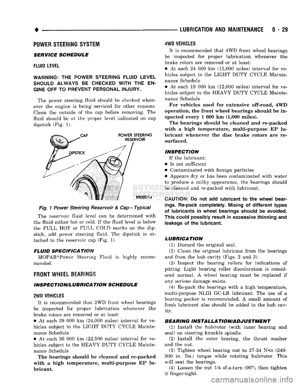
The power steering fluid should be checked when
ever the engine is being serviced for other reasons. Clean the outside of the cap before removing. The
fluid should be at the proper level indicated on cap dipstick (Fig. 1).
Fig.
1
Power
Steering Reservoir & Cap—Typical
The reservoir fluid level can be determined with
the fluid either hot or cold. If the fluid level is below
the FULL HOT or FULL COLD marks on the dip stick, add power steering fluid. The dipstick is at
tached to the reservoir cap (Fig. 1).
FLUID SPECIFICATION MOPAR03)Power Steering Fluid is highly recom
mended.
FRONT
WHEEL BEARINGS
INSPECTION/LUBRICATION SCHEDULE
2WD
VEHICLES
It is recommended that 2WD front wheel bearings
be inspected for proper lubrication whenever the
brake rotors are removed or at least: • At each 39 000 km (24,000 miles) interval for ve
hicles subject to the LIGHT DUTY CYCLE Mainte nance Schedule • At each 36 000 km (22,500 miles) interval for ve
hicles subject to the HEAVY DUTY CYCLE Mainte nance Schedule The bearings should be cleaned and re-packed
with a high temperature, multi-purpose EP lu
bricant.
4WD
VEHICLES
It is recommended that 4WD front wheel bearings
be inspected for proper lubrication whenever the
brake rotors are removed or at least:
• At each 24 000 km (15,000 miles) interval for ve
hicles subject to the LIGHT DUTY CYCLE Mainte nance Schedule
• At each 19 000 km (12,000 miles) interval for ve
hicles subject to the HEAVY DUTY CYCLE Mainte nance Schedule
For vehicles used for extensive off-road, 4WD
operation, the front wheel bearings should be in spected every 1 600 km (1,000 miles).
The bearings should be cleaned and re-packed
with a high temperature, multi-purpose EP lu
bricant whenever the disc brake rotors are re surfaced.
INSPECTION If the lubricant:
• Is not sufficient
• Contaminated with foreign particles
• Appears dry or has been contaminated with water
to produce a milky appearance, the bearings should
be cleaned and re-packed with lubricant.
CAUTION:
Do not add
lubricant
to the
wheel
bear
ings.
Re-pack completely. Mixing
of
different
types
of lubricants
in
wheel
bearings should
be
avoided.
This could possibly result
in
excessive thinning
and
leakage
of the
lubricant.
LUBRICATION (1) Discard the original seal.
(2) Clean the original lubricant from the bearings
and from the hub cavity (Figs. 2 and 3).
(3) Inspect the bearing rollers for indications of
pitting. Light bearing roller discoloration is consid ered normal. A wheel bearing must be replaced if any serious damage exists.
(4) Re-pack the bearings with a high temperature,
multi-purpose NLGI GC-LB lubricant. The use of a
bearing packer is recommended. A small amount of fresh lubricant also should be added to the hub cav ity.
BEARING INSTALLA TION/ADJUSTMENT (1) Install the hub/rotor (with inner bearing and
seal) on steering knuckle spindle.
(2) Install the outer bearing, the thrust washer
and the nut.
(3) Tighten wheel bearing nut to 27-34 N^m (240-
300 in. lbs.) torque while rotating hub/rotor. This
will seat the bearings.
(4) Loosen the nut 1/4 of-a-turn (90°), then tighten
it finger-tight.
Page 60 of 1502
•
FRONT
SUSPENSION
AND
AXLE
2 • 7
FRONT SUSPENSION
—2WD
VEHICLES
INDEX
page
Coil Springs
9
Lower Ball Stud
. 10
Lower Suspension
Arm 10
Lower Suspension
Arm
Bushing
11
Lower Suspension
Arm
Strut
8
Service
Information
7
Shock
Absorber
9
page
Stabilizer
Bar 8
Steering Knuckle
13
Upper Ball Stud
11
Upper Suspension
Arm 11
Upper Suspension
Arm
Bushing Replacement
. . . 12
Wheel
Hub and
Bearings
7
SERVICE
INFORMATION
Periodic lubrication of the front suspension (steer
ing) system components is required. Refer to Group 0, Lubrication And Maintenance for the service in
terval.
Rubber bushings must never be lubricated.
All front suspension components that are
cushioned by rubber should be tightened with
the suspension system at the normal height.
WHEEL
HUB
AND
BEARINGS
REMOVAL (1) Block the brake pedal in the up (non-depressed)
position.
(2) Raise and support the vehicle.
(3) Remove the wheel.
(4) Remove bolts from the disc brake caliper.
(5) Separate the disc brake caliper from the rotor.
Position and support the caliper away from the im
mediate work area. Do not allow the caliper to
hang from the brake fluid hose.
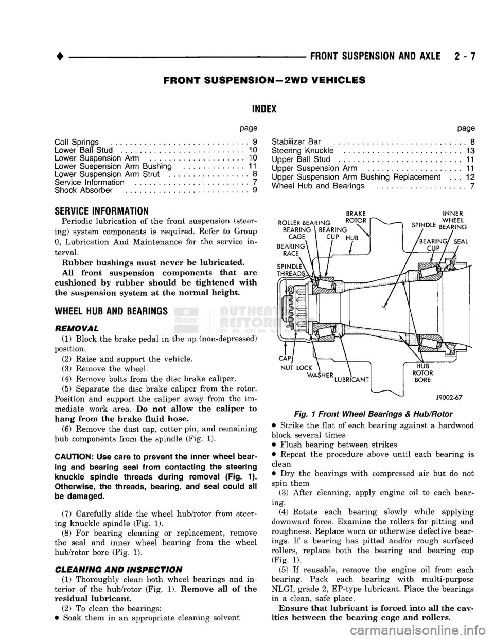
(6) Remove the dust cap, cotter pin, and remaining
hub components from the spindle (Fig. 1).
CAUTION:
Use care
to
prevent
the
inner wheel bear
ing
and
bearing seal from contacting
the
steering
knuckle spindle threads during removal
(Fig. 1).
Otherwise,
the
threads, bearing,
and
seal could
all
be damaged.
(7) Carefully slide the wheel hub/rotor from steer
ing knuckle spindle (Fig. 1).
(8) For bearing cleaning or replacement, remove
the seal and inner wheel bearing from the wheel
hub/rotor bore (Fig. 1).
CLEANING AND INSPECTION (1) Thoroughly clean both wheel bearings and in
terior of the hub/rotor (Fig. 1). Remove all of the residual lubricant.
(2) To clean the bearings:
• Soak them in an appropriate cleaning solvent
BRAKE
INNER
Fig.
1 Front
Wheel
Bearings
&
Hub/Rotor
• Strike the flat of each bearing against a hardwood
block several times • Flush bearing between strikes
• Repeat the procedure above until each bearing is
clean
• Dry the bearings with compressed air but do not spin them
(3) After cleaning, apply engine oil to each bear
ing. (4) Rotate each bearing slowly while applying
downward force. Examine the rollers for pitting and
roughness. Replace worn or otherwise defective bear
ings.
If a bearing has pitted and/or rough surfaced
rollers, replace both the bearing and bearing cup (Fig. 1).
(5) If reusable, remove the engine oil from each
bearing. Pack each bearing with multi-purpose NLGI, grade 2, EP-type lubricant. Place the bearings
in a clean, safe place.
Ensure that lubricant is forced into all the cav
ities between the bearing cage and rollers.
Page 61 of 1502
2
- 8
FRONT SUSPENSION
AND
AXLE
• INSTALLATION
(1) If a bearing and cup must be replaced, remove
the cup from the wheel hub/rotor bore (Fig. 1). Use a
brass drift or an appropriate removal tool to tap out
the cup.
(2) Install the replacement bearing cup(s) with an
appropriate installation tool. (3) Apply lubricant to surface area of the wheel
hub/rotor bore. Install the inner wheel bearing in the
hub/rotor. Install a replacement bearing seal with an appropriate seal installation tool. (4) Inspect the bearing and seal contact surfaces on
the steering knuckle spindle for burrs and/or rough ness (Fig. 1).
(5) Remove all the rough contact surfaces from the
spindle. Apply a coating of multi-purpose NLGI,
grade 2, EP-type lubricant to the spindle surface.
CAUTION: Us© care to prevent the inner
wheel
bear
ing
and bearing
seal
from contacting the steering
knuckle
spindle
threads during removal (Fig. 1).
Otherwise,
the threads, bearing, and
seal
could
be
damaged.
(6) Carefully slide the wheel hub/rotor onto the
spindle.
Install the outer wheel bearing, the washer and
nut.
(7) Tighten the nut to 41 to 54 Nnn (30 to 40 ft.
lbs.) torque while rotating the wheel hub/rotor. Stop
the hub/rotor and loosen the nut to completely re
lease the bearing preload torque. Next, tighten the
nut finger-tight, install the nut lock. Install a re
placement cotter pin.
(8) The wheel bearing adjustment (above) should
have 0.001 to 0.003 inch (0.254 to 0.0762 mm) end
play.
(9) Clean the dust cap. Apply a coating of multi
purpose NLGI, grade 2, EP-type lubricant to internal surface. Install the cap. Do not fill the dust cap with lubricant. (10) Install the brake caliper, refer to Group 5,
Brakes. (11) Install the wheel and tire, refer to Wheel and
Tire Installation in this section. Lower the vehicle.
LOWER SUSPENSION ARM STRUT
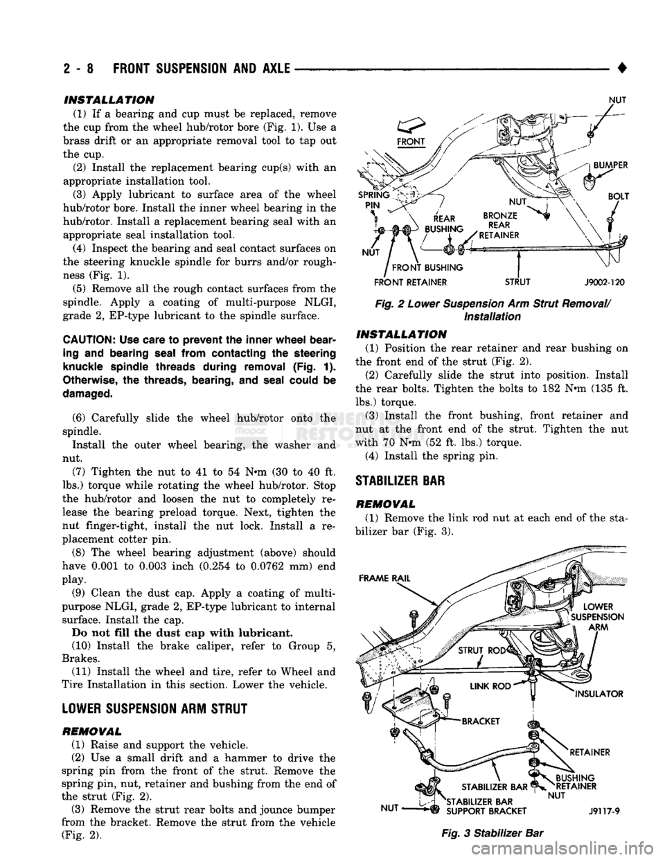
REMOVAL (1) Raise and support the vehicle.
(2) Use a small drift and a hammer to drive the
spring pin from the front of the strut. Remove the
spring pin, nut, retainer and bushing from the end of
the strut (Fig. 2).
(3) Remove the strut rear bolts and jounce bumper
from the bracket. Remove the strut from the vehicle (Fig. 2).
NUT
FRONT
RETAINER
STRUT
J9002-120
Fig. 2 Lower Suspension Arm Strut Removal/ Installation INSTALLATION
(1) Position the rear retainer and rear bushing on
the front end of the strut (Fig. 2).
(2) Carefully slide the strut into position. Install
the rear bolts. Tighten the bolts to 182 Nnn (135 ft. lbs.) torque.
(3) Install the front bushing, front retainer and
nut at the front end of the strut. Tighten the nut
with 70 Nnn (52 ft. lbs.) torque.
(4) Install the spring pin.
STABILIZER
BAR
REMOVAL
(1) Remove the link rod nut at each end of the sta
bilizer bar (Fig. 3). Fig. 3 Stabilizer Bar
Page 63 of 1502
2
- 10
FRONT SUSPENSION
AND
AXLE
• INSTALLATION
(1) Position the spring and isolation pad on the
suspension arm. Install the spring compressor tool.
Compress the spring until the lower suspension arm
can be properly positioned in the steering knuckle.
(2) Install the nuts on the ball studs. Tighten the
upper nut to 142 Nnn (105 ft. lbs.) torque. Tighten
the lower nut.
* 11/16-16 bolt, to 183 Nnn (135 ft. lbs.) torque
• 3/4-16 bolt, to 237 Nnn (175 ft. lbs.) torque Install replacement cotter pins.
(3) Install the strut.
(4) Connect the stabilizer bar.
(5) Install the shock absorber.
(6) Install the brake splash shield on the steering
knuckle. Tighten the screws to 23 Nnn (200 in. lbs.)
torque.
(7) Carefully install the hub/rotor and bearings.
(8) Install the brake caliper, refer to Group 5, Brakes.
(9) Install the wheel and tire, refer to Wheel and Tire
Installation within this section. Lower the vehicle. (10) Test the vehicle brakes and the suspension for
proper operation.
LOWER SUSPENSION
ARM
REMOVAL
(1) Follow procedure under Coil Spring Removal.
(2) Remove hex-head mounting bolt from the cross-
member. (3) Remove the lower suspension arm from vehicle.
INSTALLATION (1) Position lower suspension arm on vehicle.
(2) Install mounting bolt, tighten finger-tight.
(3) Follow procedure under Coil Spring Installa
tion.
(4) Lower the vehicle to the surface with the
wheels/tires supporting the vehicle weight. Tighten
the lower suspension arm mounting bolt to 305 Nnn (225 ft. lbs.) torque.
LOWER
BALL
STUD
INSPECTION
(1) Raise the front of the vehicle. Install safety
floor stands under both lower suspension arms as far outboard as possible. The upper suspension arms
must not contact the rebound bumpers. (2) Install a dial indicator and clamp assembly to
the lower suspension arm. (3) Position indicator plunger against knuckle arm
and zero indicator. (4) Raise and lower the wheel with a pry bar under
the center of the tire. Measure the axial movement of
the knuckle with respect to the suspension arm.
(5) If the travel of the suspension arm is 0.020
inch (0.51 mm) or more, replace the ball joint. REMOVAL
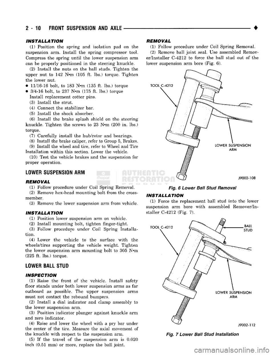
(1) Follow procedure under Coil Spring Removal.
(2) Remove ball joint seal. Use assembled Remov
er/Installer C-4212 to force the ball stud out of the
lower suspension arm bore (Fig. 6).
Fig.
6
Lower
Bail
Stud
Removal
INSTALLATION (1) Force the replacement ball stud into the lower
suspension arm bore with assembled Remover/In
staller C-4212 (Fig. 7).
Fig.
7
Lower
Ball
Stud
Installation
Page 66 of 1502
•
Fig.
11 Upper Suspension Arm Bushing installation
STEERING KNUCKLE
REMOVAL
(1) Block the brake pedal in the up position. Raise
the vehicle and remove the wheel cover and wheel/
tire.
Remove the brake caliper, refer to Group 5,
Brakes. (2) Remove the brake rotor from the spindle. Refer
to Wheel Hub and Bearings service procedures
within this Group.
(3) Remove the brake splash shield. Remove and
discard the dust seal.
(4) Remove the cotter pin and the nut from the tie-
rod end ball stud.
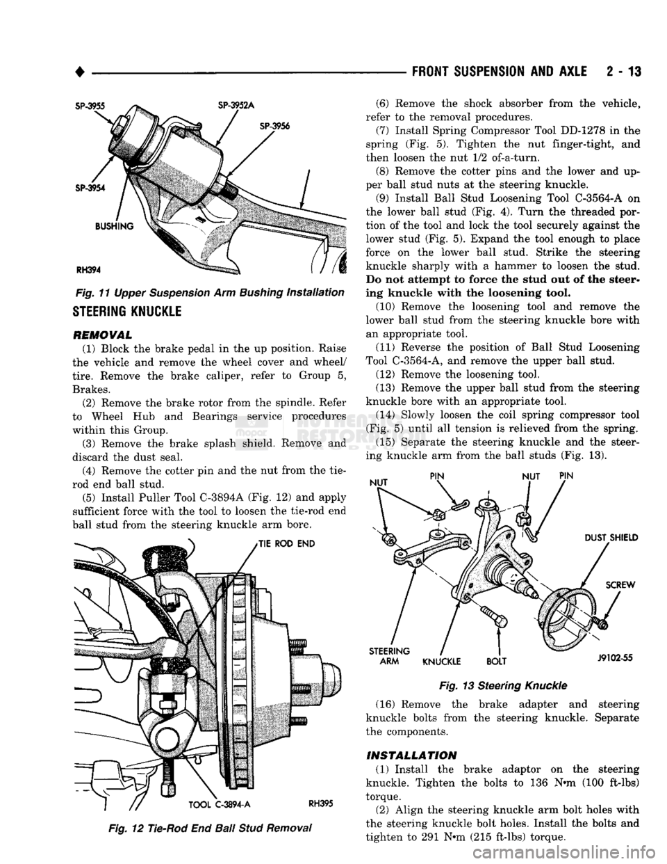
(5)
Install Puller Tool C-3894A (Fig. 12) and apply
sufficient force with the tool to loosen the tie-rod end
ball stud from the steering knuckle arm bore.
Fig.
12 Tie-Rod End
Ball
Stud
Removal
FRONT SUSPENSION
AND
AXLE
2 - 13
Fig.
13 Steering
Knuckle
(16) Remove the brake adapter and steering
knuckle bolts from the steering knuckle. Separate
the components.
INSTALLATION (1) Install the brake adaptor on the steering
knuckle. Tighten the bolts to 136 Nnn (100 ft-lbs)
torque.
(2) Align the steering knuckle arm bolt holes with
the steering knuckle bolt holes. Install the bolts and
tighten to 291 Nnn (215 ft-lbs) torque. (6) Remove the shock absorber from the vehicle,
refer to the removal procedures. (7) Install Spring Compressor Tool DD-1278 in the
spring (Fig. 5). Tighten the nut finger-tight, and
then loosen the nut 1/2 of-a-turn.
(8) Remove the cotter pins and the lower and up
per ball stud nuts at the steering knuckle.
(9) Install Ball Stud Loosening Tool C-3564-A on
the lower ball stud (Fig. 4). Turn the threaded por
tion of the tool and lock the tool securely against the lower stud (Fig. 5). Expand the tool enough to place
force on the lower ball stud. Strike the steering
knuckle sharply with a hammer to loosen the stud.
Do not attempt to force the stud out of the steer
ing knuckle with the loosening tool.
(10) Remove the loosening tool and remove the
lower ball stud from the steering knuckle bore with an appropriate tool.
(11) Reverse the position of Ball Stud Loosening
Tool C-3564-A, and remove the upper ball stud.
(12) Remove the loosening tool.
(13) Remove the upper ball stud from the steering
knuckle bore with an appropriate tool. (14) Slowly loosen the coil spring compressor tool
(Fig. 5) until all tension is relieved from the spring.
(15) Separate the steering knuckle and the steer
ing knuckle arm from the ball studs (Fig. 13).
Page 67 of 1502
2
- 14
FRONT SUSPENSION
AND
AXLE
• (3) Mount the knuckle to the suspension arms and
install the nuts. Tighten the upper nut to 142 Nnn (105 ft-lbs) torque and the lower nut.
• 11/16-16 bolt, to 183 Nnn (135 ft-lbs) torque
• 3/4-16 bolt, to 237 Nnn (175 ft-lbs) torque Install replacement cotter pins. (4) Connect the tie-rod end. Install and tighten the
nut to 61 Nnn (45 ft-lbs) torque. Install a replace
ment cotter pin. (5) Position a replacement dust seal on the steer
ing knuckle. Install the splash shield and tighten the
bolts to 24 Nnn (18 ft. lbs.) torque. (6) Install the shock absorber, refer to the installa
tion procedures.
(7) Install the hub/rotor, refer to the procedures
above.
(8) Install the brake caliper, refer to Group 5,
Brakes for additional installation information.
(9)
Install the wheel and tire, refer to Wheel and
Tire Installation in this section. Lower the vehicle.
(10) Test the vehicle brakes and the front suspen
sion for proper operation.
FRONT
SUSPENSION—4WD VEHICLES
STABILIZER
BAR REMOVAL
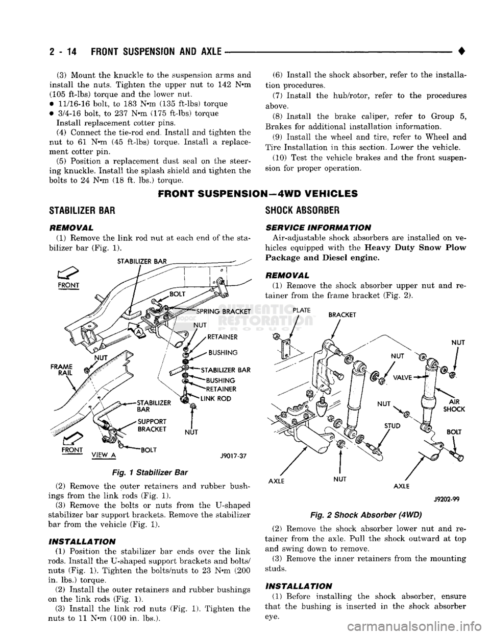
(1) Remove the link rod nut at each end of the sta
bilizer bar (Fig. 1).
STABILIZER BAR
FRONT
STABILIZER BAR BUSHING
RETAINER
LINK
ROD
J9017-37
Fig.
1
Stabilizer
Bar (2) Remove the outer retainers and rubber bush
ings from the link rods (Fig. 1). (3) Remove the bolts or nuts from the U-shaped
stabilizer bar support brackets. Remove the stabilizer
bar from the vehicle (Fig. 1).
INSTALLATION (1) Position the stabilizer bar ends over the link
rods.
Install the U-shaped support brackets and bolts/
nuts (Fig. 1). Tighten the bolts/nuts to 23 Nnn (200
in. lbs.) torque.
(2) Install the outer retainers and rubber bushings
on the link rods (Fig. 1). (3) Install the link rod nuts (Fig. 1). Tighten the
nuts to 11 Nnn (100 in. lbs.).
SHOCK
ABSORBER
SERVICE INFORM
A TION Air-adjustable shock absorbers are installed on ve
hicles equipped with the Heavy Duty Snow Plow Package and Diesel engine.
REMOVAL
(1) Remove the shock absorber upper nut and re
tainer from the frame bracket (Fig. 2).
PLATE
BRACKET
NUT
AXLE NUT
AXLE
J9202-99
Fig.
2
Shock
Absorber
(4
WD)
(2) Remove the shock absorber lower nut and re
tainer from the axle. Pull the shock outward at top and swing down to remove.
(3) Remove the inner retainers from the mounting
studs.
INSTALLATION (1) Before installing the shock absorber, ensure
that the bushing is inserted in the shock absorber
eye.