1993 DODGE TRUCK service indicator
[x] Cancel search: service indicatorPage 33 of 1502

0 - 14
LUBRICATION
AND
MAINTENANCE
•
ENGINE
MAINTENANCE
INDEX
page
Air
Injection
Systems/Air Pump
. 17
Air-Conditioner
Compressor
21
Battery
19
Cooling System
15
Crankcase
Ventilation
System
17
Diesel Engine
Air Filter
Canister
17
Drive Belts
20
Engine
Air
Cleaner
Filter
Element
16
Engine Break-In
14
Engine
Oil 14
Engine
Oil
Change
and Filter
Replacement
15
Exhaust Gas
Recirculation
(EGR) System
...... 19
page
Exhaust
Manifold
Heat
Control
Valve
. 17
Exhaust System
, 21
Fuel System
18
Hoses
and
Fittings
16
Ignition
Cables,
Distributor
Cap and
Rotor
...... 19
Ignition
Timing
. 19
Oxygen
(02)
Sensor
19
Rubber/Plastic Components
20
Spark Plugs
. 19
Throttle
Control
Linkage
18
Vacuum Operated, Emission
Control
Components
19
ENGINE BREAK-IN
After first starting a new engine, allow it to idle
for 15 seconds before shifting into a drive gear. Also:
• Drive the vehicle at varying speeds less than 88
km/h (55 mph) for the first 480 km (300 miles).
• Avoid fast acceleration and sudden stops.
• Do not drive at full-throttle for extended periods of
time
• Do not drive at constant speeds
• Do not idle the engine excessively A special break-in engine oil is not required. The
original engine oil installed is a high quality lubri
cant. New engines tend to consume more fuel and oil un
til after the break-in period has ended.
ENGINE
OIL SPECIFICATIONS
API SERWICE
GRADE
Use an engine oil that conforms to API Service
Grade S5 SG/CD or SG/CE. MOPAR®provides engine
oils that conform to all of these service grades.
SULFATED ASH—DIESEL ENGINES
Oils that contain an excessive amount of sulfated
ash can cause deposits to develop on Diesel engine
valves. These deposits can result in valve wear.
SAE
WISC0SITY
An SAE viscosity grade is used to specify the vis
cosity of engine oil. SAE 30 specifies a single viscos
ity engine oil.
Engine oils also have multiple viscosities. 10W-30
<
5W-30
1
1 1
F
-20 0 10 20 32 60 80 100
C
-29 -18 -12 -7 0 16 27 38
ANTICIPATED
TEMPERATURE RANGE BEFORE
NEXT
OIL
CHANGE
J9000-39
Fig.
1 Temperature/Engine Oil Viscosity—Gasoline
Engines
-12°C
-18°C 10°F
0°F- 15W-40
-23°c(^-10eF
I
10W-30
WITH
WITHOUT
BLOCK HEATER
BLOCK
SYNTHETIC
OIL
HEATER
10W-30 5W-30
J9100-29
Fig.
2 Temperature/Engine Oil Viscosity—Diesel
Engines
ENERGY
G0NSERWING
OIL
An Energy Conserving type oil is recommended for
gasoline engines. They are designated as either EN
ERGY CONSERVING or ENERGY CONSERVING
II.
OIL
LEVEL
INDICATOR (DIPSTICK)
GASOLINE ENGINES
The engine oil indicator is located at the right
front of the engine.
Page 34 of 1502

•
LUBRICATION
AND
MAINTENANCE
0 - 15
DIESEL
ENGINES
The Diesel engine oil level indicator is located at
the left center of the engine, above the
fuel
injection
pump (Fig. 3).
Fig.
3
Diesel
Engine
Oil
Dipstick
ACCEPTABLE
OIL
LEVEL
To maintain proper lubrication of an engine, the
engine oil must be maintained at an acceptable level.
For gasoline engines, the acceptable levels are indi cated between the ADD and
FULL
marks on oil
dip
stick. For Diesel engines, the acceptable levels are
indicated between the L (low) and H
(high) marks
on
oil dipstick. The oil level should be checked periodically. The
vehicle should be on a level surface. Wait for
five
minutes after stopping the engine. For gasoline en
gines,
add oil only when the level indicated on the
dipstick is at or below the ADD mark. For Diesel en
gines,
add oil only when the level indicated on the
dipstick is between the L and H marks.
Never oper
ate a Diesel
engine when
the oil
level
is below
the L mark. The distance between the L and H
marks represents 1.9L (2 Qts) engine oil.
CAUTION:
Do not
overfill
an
engine crankcase
with
oil. This
will
cause
oil
aeration
and
result
in a de
crease
in the
engine
oil
pressure.
ENGINE
OIL
CHANGE AND FILTER REPLACEMENT
WARNING: PROTECTIVE CLOTHING
AND
GLOVES SHOULD
BE
WORN. EXPOSED SKIN SHOULD
BE
WASHED
WITH
SOAP
AND
WATER
TO
REMOVE
USED
ENGINE
OIL.
DO NOT
USE
GASOLINE, THIN
NER,
OR
SOLVENTS
TO
REMOVE ENGINE
OIL
FROM
SKIN.
DO NOT
POLLUTE. DISPOSE
OF
USED
ENGINE
OIL
PROPERLY.
ENGINE
OIL
FILTER
All engines are equipped with a throw-away type
oil filter. The same type of filter is recommended
when the filter is changed.
OIL CHANGE
AND
FILTER
REPLACEMENT
Bring engine up to normal operating temperature.
A more complete drainage of oil will result.
(1) Remove the drain hole plug and drain the en
gine oil from the crankcase.
(2) Install the drain hole plug with a replacement
gasket. For gasoline engines, the oil filter should be
replaced during every second engine oil change.
For Diesel engines, the oil filter should be re
placed during every engine oil change.
(3) Rotate the oil filter counterclockwise to remove
it.
(4) Clean the engine cylinder block oil filter boss. (5) Apply a light coat of new engine oil to the rub
ber seal on the oil filter.
(6) Install and hand tighten the oil filter 1/2 to 3/4
of a turn clockwise. (7) Add new engine oil at the fill hole location on
top of the engine cylinder head cover. Wipe off any spilled oil.
(8) Observe the oil level on the dipstick.
CAUTION:
Do not
overfill
the
engine crankcase
with
oil.
(9)
Start the engine. Observe the oil pressure
gauge or warning lamp (as applicable). If the oil
pressure does not increase, stop the engine immedi ately. Check oil level.
COOLING SYSTEM
WARNING:
USE
EXTREME CAUTION WHEN
THE
ENGINE
IS
OPERATING.
DO NOT PUT
YOUR
HANDS NEAR
THE
DRIVE BELT(S), PULLEYS
OR
FAN BLADE.
DO NOT
STAND
IN A
DIRECT LINE
WITH
THE FAN
BLADE.
INSPECTION SCHEDULE
Determine the coolant level. Inspect the cooling
system hoses/clamps after each service interval has
elapsed.
COOLANT LEVEL
It is recommended that the engine coolant level be
inspected at least once a month during periods of hot
weather.
With the engine at normal operating temperature,
check the coolant level in the coolant reserve tank.
The coolant level must be at least above the ADD mark. Add coolant to the coolant reserve tank only.
Page 39 of 1502
0
- 21
LUBRICATION
AND
MAINTENANCE
• SERVICE INFORMATION
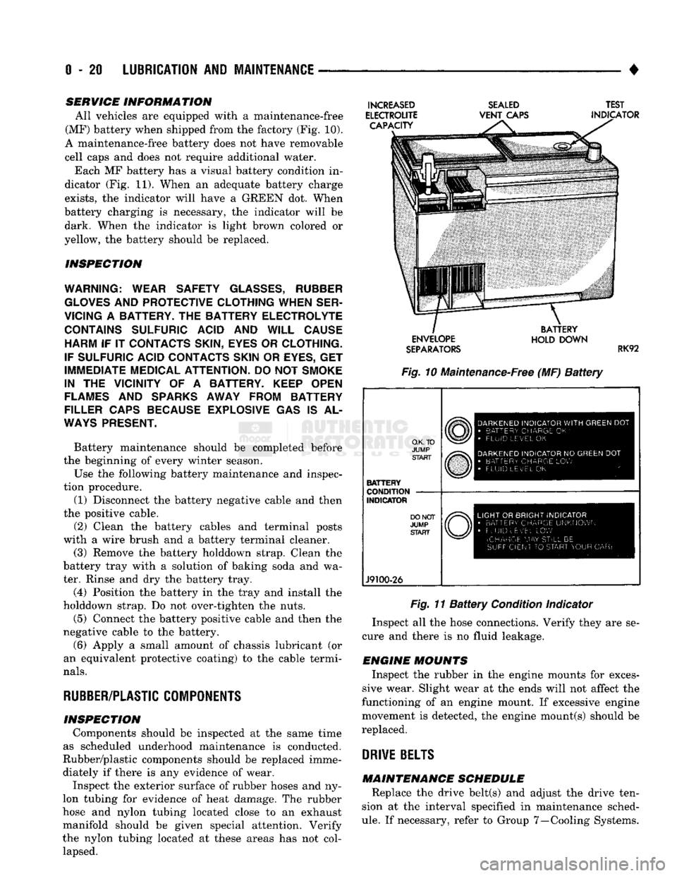
All vehicles are equipped with a maintenance-free
(MF) battery when shipped from the factory (Fig. 10).
A maintenance-free battery does not have removable
cell caps and does not require additional water. Each MF battery has a visual battery condition in
dicator (Fig. 11). When an adequate battery charge
exists,
the indicator will have a GREEN dot. When
battery charging is necessary, the indicator will be dark. When the indicator is light brown colored or
yellow, the battery should be replaced.
INSPECTION
WARNING; WEAR SAFETY
GLASSES,
RUBBER
GLOVES
AND
PROTECTIVE CLOTHING WHEN SER
VICING
A
BATTERY.
THE
BATTERY ELECTROLYTE CONTAINS SULFURIC ACID
AND
WILL CAUSE HARM
IF IT
CONTACTS SKIN, EYES
OR
CLOTHING.
IF SULFURIC ACID CONTACTS SKIN
OR
EYES,
GET
IMMEDIATE MEDICAL ATTENTION.
DO
NOT
SMOKE
IN
THE
VICINITY
OF A
BATTERY. KEEP OPEN
FLAMES
AND
SPARKS AWAY FROM BATTERY
FILLER CAPS BECAUSE EXPLOSIVE
GAS IS AL
WAYS
PRESENT.
Battery maintenance should be completed before
the beginning of every winter season.
Use the following battery maintenance and inspec
tion procedure. (1) Disconnect the battery negative cable and then
the positive cable.
(2) Clean the battery cables and terminal posts
with a wire brush and a battery terminal cleaner. (3) Remove the battery holddown strap. Clean the
battery tray with a solution of baking soda and wa
ter. Rinse and dry the battery tray.
(4) Position the battery in the tray and install the
holddown strap. Do not over-tighten the nuts.
(5) Connect the battery positive cable and then the
negative cable to the battery.
(6) Apply a small amount of chassis lubricant (or
an equivalent protective coating) to the cable termi
nals.
RUBBER/PLASTIC
COMPONENTS
INSPECTION Components should be inspected at the same time
as scheduled underhood maintenance is conducted.
Rubber/plastic components should be replaced imme diately if there is any evidence of wear. Inspect the exterior surface of rubber hoses and ny
lon tubing for evidence of heat damage. The rubber
hose and nylon tubing located close to an exhaust
manifold should be given special attention. Verify
the nylon tubing located at these areas has not col lapsed.
INCREASED
ELECTROUTE CAPACITY
SEALED
VENT
CAPS TEST
INDICATOR ENVELOPE
SEPARATORS
BATTERY
HOLD DOWN
RK92
Fig. 10 Maintenance-Free (MF)
Battery
O.K. TO
JUMP START
BATTERY
CONDITION
INDICATOR
J9100-26
DARKENED
INDICATOR
WITH
GREEN
DOT
•
BATTERY CHARGE
OK '
•
FLUID LEVEL
OK
DARKENED
INDICATOR
NO
GREEN
DOT
•
BATTERY CHARGE
LOW
FLUID LEVEL
OK
LIGHT
OR
BRIGHT INDICATOR
•
BATTERY CHARGE UNKNOWN
•
FLUID uEv'EL
LOW
(CHARGE
MAY
STILL
BE
SUFFICIENT
TO
START YOUR
CAR)
Fig. 11
Battery
Condition Indicator
Inspect all the hose connections. Verify they are se
cure and there is no fluid leakage.
ENGINE MOUNTS Inspect the rubber in the engine mounts for exces
sive wear. Slight wear at the ends will not affect the
functioning of an engine mount. If excessive engine
movement is detected, the engine mount(s) should be
replaced.
DRIVE
BELTS
MAINTENANCE SCHEDULE Replace the drive belt(s) and adjust the drive ten
sion at the interval specified in maintenance sched
ule.
If necessary, refer to Group 7—Cooling Systems.
Page 135 of 1502
3
- 6
REAR SUSPENSION
AND
AXLE
•
NUT PIPE
SOCKET
WRENCH
(DRIVER)
FLAT
THREADED
WASHER
ROD
J8917-20
Fig.
6
Spring
Eye
Bushing
Removal
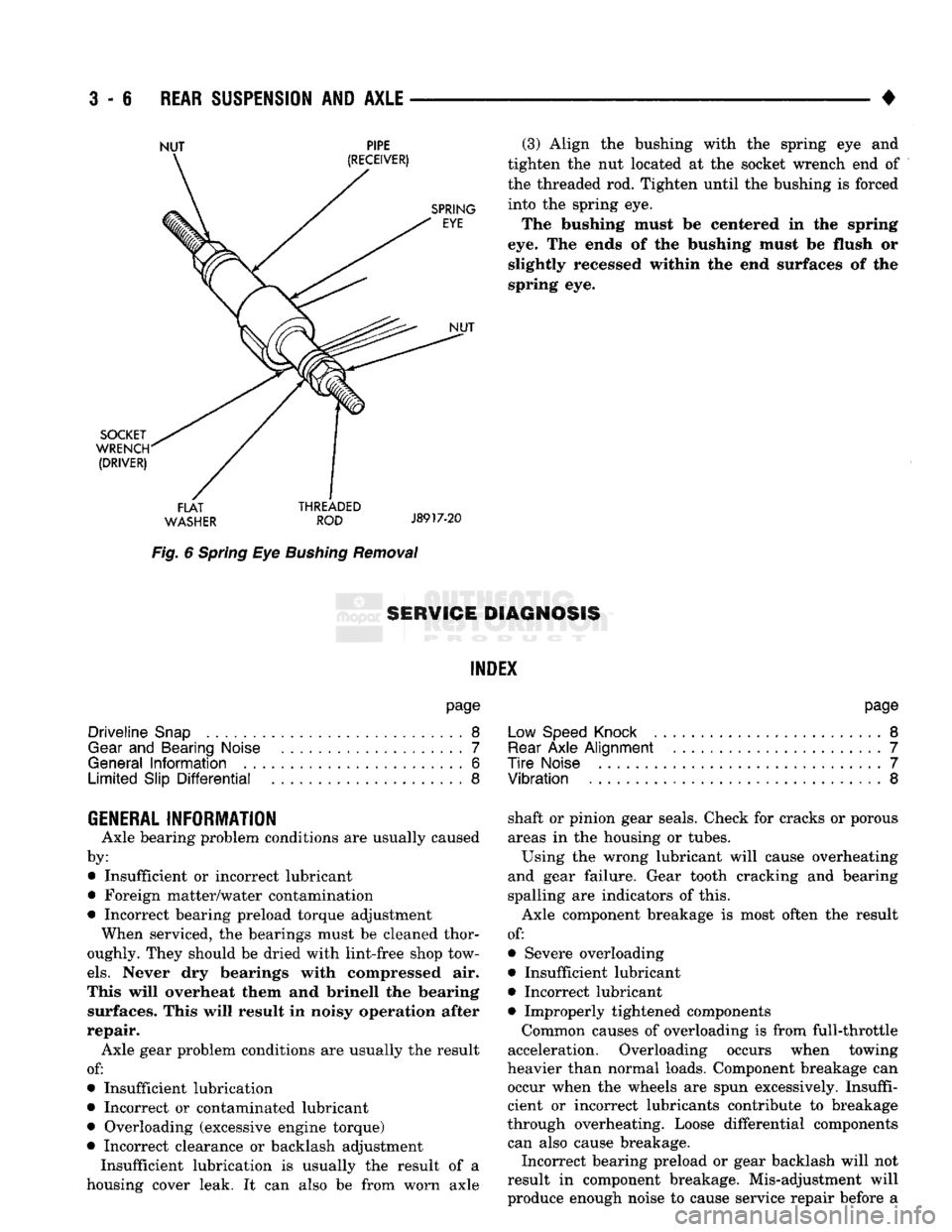
(3) Align
the
bushing with
the
spring
eye and
tighten
the nut
located
at the
socket wrench
end of
the threaded
rod.
Tighten until
the
bushing
is
forced into
the
spring
eye.
The bushing must
be
centered
in the
spring
eye.
The
ends
of the
bushing must
be
flush
or
slightly recessed within
the end
surfaces
of the
spring
eye.
8ERW1GE DIAGNOSIS
INDEX
page
Driveline
Snap
8
Gear
and
Bearing Noise
7
General
Information
6
Limited
Slip
Differential
8
page
Low Speed Knock
.........................
8
Rear
Axle
Alignment
.......................
7
Tire
Noise
7
Vibration
8
GENERAL INFORMATION
Axle bearing problem conditions
are
usually caused
by: • Insufficient
or
incorrect lubricant
• Foreign matter/water contamination
• Incorrect bearing preload torque adjustment When serviced,
the
bearings must
be
cleaned thor
oughly. They should
be
dried with lint-free shop tow
els.
Never
dry
bearings with compressed
air.
This will overheat them
and
brinell
the
bearing surfaces. This will result
in
noisy operation after
repair. Axle gear problem conditions
are
usually
the
result
of:
• Insufficient lubrication
• Incorrect
or
contaminated lubricant
• Overloading (excessive engine torque)
• Incorrect clearance
or
backlash adjustment Insufficient lubrication
is
usually
the
result
of a
housing cover leak.
It can
also
be
from worn axle shaft
or
pinion gear seals. Check
for
cracks
or
porous
areas
in the
housing
or
tubes.
Using
the
wrong lubricant will cause overheating
and gear failure. Gear tooth cracking
and
bearing
spalling
are
indicators
of
this.
Axle component breakage
is
most often
the
result
of:
• Severe overloading
• Insufficient lubricant
• Incorrect lubricant • Improperly tightened components
Common causes
of
overloading
is
from full-throttle
acceleration. Overloading occurs when towing
heavier than normal loads. Component breakage
can
occur when
the
wheels
are
spun excessively. Insuffi
cient
or
incorrect lubricants contribute
to
breakage
through overheating. Loose differential components can also cause breakage. Incorrect bearing preload
or
gear backlash will
not
result
in
component breakage. Mis-adjustment will
produce enough noise
to
cause service repair before
a
Page 188 of 1502
•
BRAKES
BRAKES
5 - 1
CONTENTS
page
BENDIX
DISC
BRAKE
37
BRAKE
ADJUSTMENTS-BRAKE BLEEDING .. 7
BRAKE
DIAGNOSIS
3
CHRYSLER
DISC
BRAKE
27
DRUM
BRAKES-ELEVEN
INCH 46
DRUM
BRAKES-TWELVE
INCH 50
GENERAL
INFORMATION 1
MASTER
CYLINDER-COMBINATION
page
VALVE-BRAKE
LINES 10
PARKING
BRAKES
56
POWER
BRAKE
BOOSTER-BRAKE
PEDAL .. 20
POWER
BRAKE
VACUUM PUMP-DIESEL
ENGINE
...22
REAR
WHEEL ANTILOCK (RWAL)
BRAKES
.. 59
SPECIFICATIONS
65
GENERAL INFORMATION
INDEX
page
Antilock
Rear
Wheel
Brakes
1
Brake
Components 1
BRAKE
COMPONENTS
AD models are equipped with front disc and rear
drum brakes. Power assist brakes and rear wheel an
tilock brakes are standard equipment on all models. A dual reservoir master cylinder and single or dual
diaphragm, vacuum operated power brake booster is
used for all applications. Models with the Cummins
diesel engine option are also equipped with a vacuum
pump assembly to operate the power brake booster. Front disc brake units consist of single piston, slid-
ing-type calipers with semi metallic brakeshoe lin ing. Vented disc brake rotors are used on all models. Bendix calipers are used on 4-wheel drive models
and on diesel engine models. Chrysler disc brake cal
ipers are used for all other applications. Rear drum brakes are dual shoe units with an au
tomatic adjustment mechanism. Bendix and Chrysler drum brake assemblies are used. A combination valve is used on all models. The
valve consists of a front brake metering (hold-off)
valve and a front/rear pressure differential switch. A red, brake indicator and warning light is used to
alert the driver if a pressure differential exists be
tween the front and rear hydraulic systems. The light also alerts the driver when the parking brakes
are applied. The light is located at the left side of the
instrument cluster. An additional indicator light is used for the anti-
lock system. This light is amber and is located in the
page
Brake
Fluid/Lubricants/Cleaning
Solvents
1
Brake
Safety Precautions 2
same side of the instrument cluster as the red indi
cator light. The antilock light alerts the driver if a system fault occurs.
ANTILOCK
REAR
WHEEL
BRAKES
All AD models are equipped with antilock rear
brakes. The system is designed to retard wheel lockup during periods of high wheel slip when brak
ing. Retarding wheel lockup is accomplished by modu
lating fluid pressure to the wheel brake units. Refer
to the Rear Wheel Anti-Lock Brake section for oper ation and service information.
BRAKE
FLUID/LUBRICANTS/CLEANING SOLVENTS Recommended fluid for all AD models is Mopar
brake fluid or equivalent meeting SAE J1703 and DOT 3 standards. Use Mopar multi mileage grease to lubricate cali
per slide surfaces, drum brake pivot pins and shoe contact points on the backing plates. Use GE 661 or
Dow 111 silicone grease (or equivalent) on caliper
bushings and slide pins. Use fresh brake fluid or Mopar brake cleaner to
clean or flush brake system components. These are
the only cleaning materials recommended.
Page 216 of 1502
•
BRAKES
5 - 29 presses the outboard shoe lining against the opposite
side of the rotor to complete braking action.
The application or release of fluid pressure causes
only a very slight movement of the caliper and pis
ton. At brake release, the piston and caliper return
to the non-applied position.
The brakeshoes do not retract an appreciable dis
tance from the rotor. The minimal running clearance
between the lining and rotor provides improved re sponse and reduced pedal travel. It also helps in pre
venting dirt and foreign material from lodging
between the shoe and rotor surfaces.
DISC
BRAKE
LINING WEAR COMPENSATION
Normal lining wear is compensated for by extension
of the caliper piston and by lateral movement of the cal
iper in the adapter. Piston position is also determined
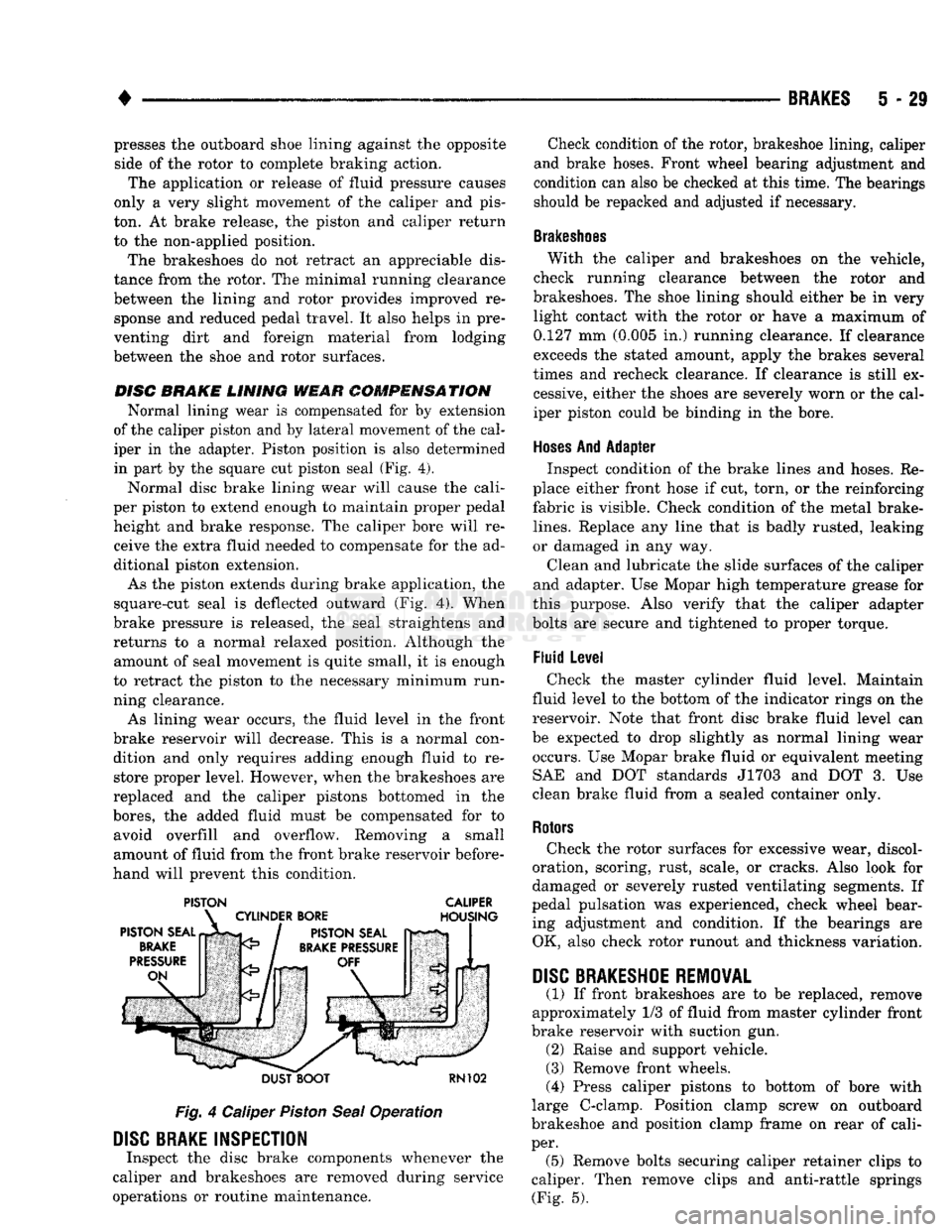
in part by the square cut piston seal (Fig. 4).
Normal disc brake lining wear will cause the cali
per piston to extend enough to maintain proper pedal height and brake response. The caliper bore will receive the extra fluid needed to compensate for the ad
ditional piston extension.
As the piston extends during brake application, the
square-cut seal is deflected outward (Fig. 4). When
brake pressure is released, the seal straightens and
returns to a normal relaxed position. Although the amount of seal movement is quite small, it is enough
to retract the piston to the necessary minimum run
ning clearance.
As lining wear occurs, the fluid level in the front
brake reservoir will decrease. This is a normal con dition and only requires adding enough fluid to restore proper level. However, when the brakeshoes are
replaced and the caliper pistons bottomed in the
bores,
the added fluid must be compensated for to avoid overfill and overflow. Removing a small
amount of fluid from the front brake reservoir before
hand will prevent this condition.
PISTON CALIPER
DUST BOOT
RN102
Fig.
4 Caliper
Piston
Seal
Operation
DISC
BRAKE INSPECTION
Inspect the disc brake components whenever the
caliper and brakeshoes are removed during service
operations or routine maintenance. Check condition of the rotor, brakeshoe lining, caliper
and brake hoses. Front wheel bearing adjustment and
condition can also be checked at this time. The bearings
should be repacked and adjusted if necessary.
Brakeshoes
With the caliper and brakeshoes on the vehicle,
check running clearance between the rotor and
brakeshoes. The shoe lining should either be in very light contact with the rotor or have a maximum of
0.127 mm (0.005 in.) running clearance. If clearance
exceeds the stated amount, apply the brakes several
times and recheck clearance. If clearance is still ex cessive, either the shoes are severely worn or the cal
iper piston could be binding in the bore.
Hoses
And Adapter Inspect condition of the brake lines and hoses. Re
place either front hose if cut, torn, or the reinforcing
fabric is visible. Check condition of the metal brake-
lines.
Replace any line that is badly rusted, leaking
or damaged in any way.
Clean and lubricate the slide surfaces of the caliper
and adapter. Use Mopar high temperature grease for
this purpose. Also verify that the caliper adapter
bolts are secure and tightened to proper torque.
Fluid Level Check the master cylinder fluid level. Maintain
fluid level to the bottom of the indicator rings on the
reservoir. Note that front disc brake fluid level can
be expected to drop slightly as normal lining wear occurs. Use Mopar brake fluid or equivalent meeting SAE and DOT standards J1703 and DOT 3. Use
clean brake fluid from a sealed container only.
Rotors
Check the rotor surfaces for excessive wear, discol
oration, scoring, rust, scale, or cracks. Also look for
damaged or severely rusted ventilating segments. If
pedal pulsation was experienced, check wheel bear ing adjustment and condition. If the bearings are OK, also check rotor runout and thickness variation.
DISC
BRAKESHOE
REMOVAL
(1) If front brakeshoes are to be replaced, remove
approximately 1/3 of fluid from master cylinder front
brake reservoir with suction gun. (2) Raise and support vehicle.
(3) Remove front wheels.
(4) Press caliper pistons to bottom of bore with
large C-clamp. Position clamp screw on outboard
brakeshoe and position clamp frame on rear of cali
per. (5) Remove bolts securing caliper retainer clips to
caliper. Then remove clips and anti-rattle springs (Fig. 5).
Page 221 of 1502
5
- 34
BRAKES
•
boot
>TALLir TOOL
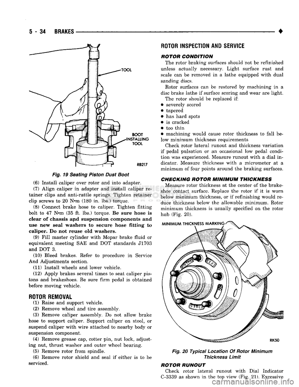
Fig.
19 Seating
Piston
Dust
Boot
(6) Install caliper over rotor and into adapter.
(7) Align caliper in adapter and install caliper re
tainer clips and anti-rattle springs. Tighten retainer clip screws to 20 N*m (180 in. lbs.) torque.
(8) Connect brake hose to caliper. Tighten fitting
bolt to 47 N»m (35 ft. lbs.) torque. Be sure hose is clear of chassis and suspension components and
use new seal washers to secure hose fitting to caliper. Do not reuse old washers.
(9) Fill master cylinder with Mopar brake fluid or
equivalent meeting SAE and DOT standards J1703 and DOT 3.
(10) Bleed brakes. Refer to procedure in Service
And Adjustments section.
(11) Install wheels and lower vehicle.
(12) Apply brakes several times to seat caliper pis
tons and brakeshoes. Be sure firm pedal is obtained
before moving vehicle.
ROTOR REMOVAL
(1) Raise and support vehicle.
(2) Remove wheel and tire assembly.
(3) Remove caliper assembly. Do not allow brake
hose to support caliper. Support caliper on stool, or suspend caliper with wire attached to nearby body or
suspension component. (4) Remove grease cap, cotter pin, nut lock, adjust
ing nut, thrust washer and outer wheel bearing. (5) Remove rotor from spindle.
(6) Remove rotor shield and seal if either is to be
serviced.
ROTOR
INSPECTION AND
SERVICE
rotor condition The rotor braking surfaces should not be refinished
unless actually necessary. Light surface rust and scale can be removed in a lathe equipped with dual
sanding discs.
Rotor surfaces can be restored by machining in a
disc brake lathe if surface scoring and wear are light.
The rotor should be replaced if:
• severely scored
• tapered
• has hard spots
• is cracked
• too thin • machining would cause rotor thickness to fall be
low minimum thickness requirements Check rotor lateral runout and thickness variation
if pedal pulsation or an occasional low pedal condi
tion was experienced. Measure runout with a dial in dicator. Measure thickness with a micrometer at a
minimum of four points around the braking surfaces.
CHECKING
ROTOR
MINIMUM
THICKNESS
Measure rotor thickness at the center of the brake-
shoe contact surface. Replace the rotor if it is worn
below minimum thickness, or if refinishing would re duce thickness below the allowable minimum. Rotor
minimum thickness is usually specified on the rotor
hub (Fig. 20).
Fig.
20 Typical Location Of Rotor
Minimum
Thickness
Limit
ROTOR RUNOUT Check rotor lateral runout with Dial Indicator
C-3339 as shown in the top view (Fig. 21). Excessive
Page 226 of 1502
BRAKES
5 - 39
DISC BRAKE LINING WEAR COMPENSATION
Normal lining wear is compensated for by exten
sion of the caliper piston and by lateral movement of
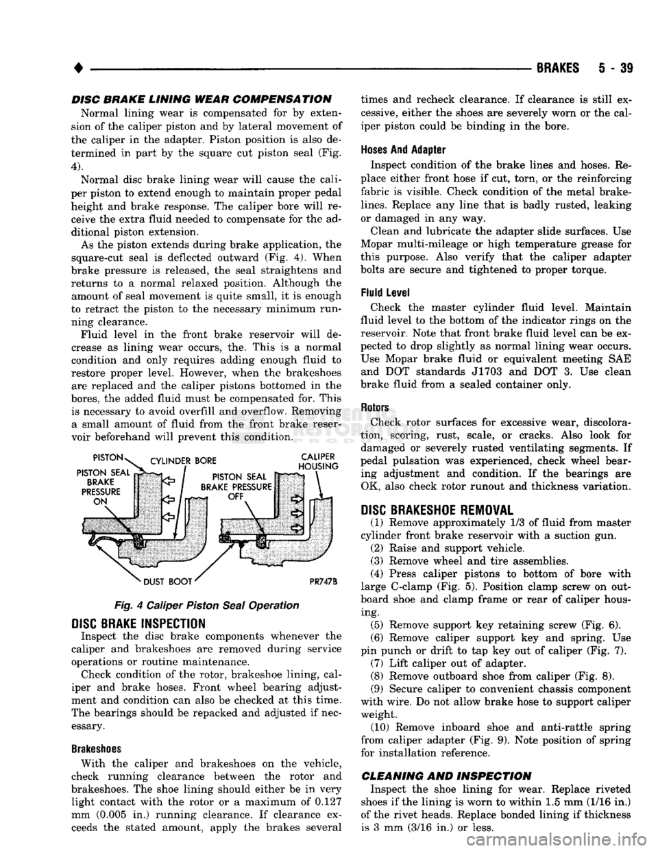
the caliper in the adapter. Piston position is also de termined in part by the square cut piston seal (Fig.
4).
Normal disc brake lining wear will cause the cali
per piston to extend enough to maintain proper pedal height and brake response. The caliper bore will receive the extra fluid needed to compensate for the ad
ditional piston extension.
As the piston extends during brake application, the
square-cut seal is deflected outward (Fig. 4). When
brake pressure is released, the seal straightens and returns to a normal relaxed position. Although the amount of seal movement is quite small, it is enough
to retract the piston to the necessary minimum run ning clearance. Fluid level in the front brake reservoir will de
crease as lining wear occurs, the. This is a normal
condition and only requires adding enough fluid to
restore proper level. However, when the brakeshoes are replaced and the caliper pistons bottomed in the
bores,
the added fluid must be compensated for. This is necessary to avoid overfill and overflow. Removing a small amount of fluid from the front brake reser
voir beforehand will prevent this condition.
Fig.
4 Caliper
Piston
Seal
Operation
DISC
BRAKE INSPECTION
Inspect the disc brake components whenever the
caliper and brakeshoes are removed during service
operations or routine maintenance. Check condition of the rotor, brakeshoe lining, cal
iper and brake hoses. Front wheel bearing adjust
ment and condition can also be checked at this time.
The bearings should be repacked and adjusted if nec essary.
Brakeshoes
With the caliper and brakeshoes on the vehicle,
check running clearance between the rotor and
brakeshoes. The shoe lining should either be in very light contact with the rotor or a maximum of 0.127
mm (0.005 in.) running clearance. If clearance exceeds the stated amount, apply the brakes several times and recheck clearance. If clearance is still ex
cessive, either the shoes are severely worn or the cal
iper piston could be binding in the bore.
Hoses
And Adapter Inspect condition of the brake lines and hoses. Re
place either front hose if cut, torn, or the reinforcing
fabric is visible. Check condition of the metal brake-
lines.
Replace any line that is badly rusted, leaking
or damaged in any way.
Clean and lubricate the adapter slide surfaces. Use
Mopar multi-mileage or high temperature grease for
this purpose. Also verify that the caliper adapter
bolts are secure and tightened to proper torque.
Fluid Level Check the master cylinder fluid level. Maintain
fluid level to the bottom of the indicator rings on the
reservoir. Note that front brake fluid level can be ex
pected to drop slightly as normal lining wear occurs.
Use Mopar brake fluid or equivalent meeting SAE and DOT standards J1703 and DOT 3. Use clean
brake fluid from a sealed container only.
Rotors
Check rotor surfaces for excessive wear, discolora
tion, scoring, rust, scale, or cracks. Also look for damaged or severely rusted ventilating segments. If
pedal pulsation was experienced, check wheel bear ing adjustment and condition. If the bearings are OK, also check rotor runout and thickness variation.
DISC
BRAKESHOE REMOVAL
(1) Remove approximately 1/3 of fluid from master
cylinder front brake reservoir with a suction gun. (2) Raise and support vehicle.
(3) Remove wheel and tire assemblies.
(4) Press caliper pistons to bottom of bore with
large C-clamp (Fig. 5). Position clamp screw on out
board shoe and clamp frame or rear of caliper hous ing. (5) Remove support key retaining screw (Fig. 6).
(6) Remove caliper support key and spring. Use
pin punch or drift to tap key out of caliper (Fig. 7). (7) Lift caliper out of adapter. (8) Remove outboard shoe from caliper (Fig. 8).
(9) Secure caliper to convenient chassis component
with wire. Do not allow brake hose to support caliper weight. (10) Remove inboard shoe and anti-rattle spring
from caliper adapter (Fig. 9). Note position of spring
for installation reference.
CLEANING AND INSPECTION Inspect the shoe lining for wear. Replace riveted
shoes if the lining is worn to within 1.5 mm (1/16 in.)
of the rivet heads. Replace bonded lining if thickness is 3 mm (3/16 in.) or less.