1993 DODGE TRUCK check transmission fluid
[x] Cancel search: check transmission fluidPage 42 of 1502
•
LUBRICATION
AND
MAINTENANCE
0 - 23 GEAR SHIFTER BOOTS
Inspect the shifter boots periodically for stone and
heat damage. Replace, if necessary.
SEVERE DRIVING CONDITIONS The interval between the transmission drain and
refill maintenance should be decreased to:
• NV4500 manual transmission—every 29 000 km (18,000 miles)
• Automatic transmission—every 19 000 km (12,000
miles)
A severe driving condition includes:
• Extended operation with heavy cargo loads
• Driving in deep mud or snow
• Off-road operation (4WD)
• Trailer towing
• Operation as a commercial vehicle
• Snow plowing
MANUAL TRANSMISSIONS
INSPECTION/LUBE
OIL
LEVEL
The transmission should be checked for leaks when
other service is necessary under the vehicle. To check
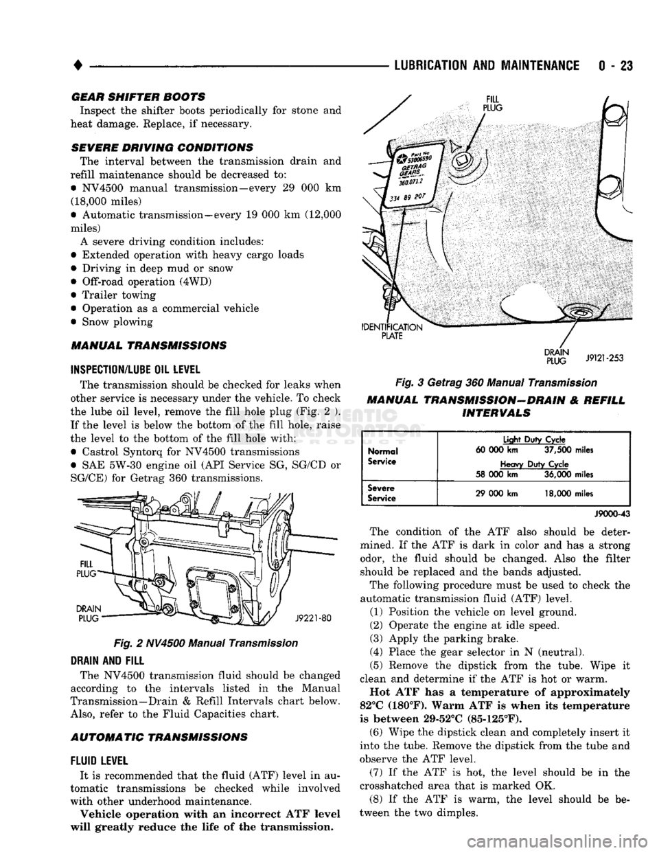
the lube oil level, remove the fill hole plug (Fig. 2 ). If the level is below the bottom of the fill hole, raise
the level to the bottom of the fill hole with:
• Castrol Syntorq for NV4500 transmissions
• SAE 5W-30 engine oil (API Service SG, SG/CD or
SG/CE) for Getrag 360 transmissions.
Fig.
2 NV4500 Manual
Transmission
DRAIN
AND
FILL
The NV4500 transmission fluid should be changed
according to the intervals listed in the Manual
Transmission—Drain & Refill Intervals chart below.
Also,
refer to the Fluid Capacities chart.
AUTOMATIC TRANSMISSIONS
FLUID
LEWEL
It is recommended that the fluid (ATF) level in au
tomatic transmissions be checked while involved
with other underhood maintenance.
Vehicle operation with an incorrect ATF level
will greatly reduce the life of the transmission.
Fig.
3 Getrag 360 Manual
Transmission
MANUAL TRANSMISSION-DRAIN & REFILL INTERVALS
Normal
Service
Light
Duty
Cycle
60 000
km
37,500
miles
Heavy
Duty
Cycle
58 000
km
36,000
miles
Severe
Service
29 000
km
18,000
miles
J9000-43
The condition of the ATF also should be deter
mined. If the ATF is dark in color and has a strong odor, the fluid should be changed. Also the filter should be replaced and the bands adjusted.
The following procedure must be used to check the
automatic transmission fluid (ATF) level.
(1) Position the vehicle on level ground.
(2) Operate the engine at idle speed.
(3) Apply the parking brake.
(4) Place the gear selector in N (neutral).
(5) Remove the dipstick from the tube. Wipe it
clean and determine if the ATF is hot or warm.
Hot ATF has a temperature of approximately
82°C (180°F). Warm ATF is when its temperature
is between 29-52°C (85-125°F). (6) Wipe the dipstick clean and completely insert it
into the tube. Remove the dipstick from the tube and
observe the ATF level.
(7) If the ATF is hot, the level should be in the
crosshatched area that is marked OK.
(8) If the ATF is warm, the level should be be
tween the two dimples.
Page 43 of 1502
0
- 24
LUBRICATION
AND
MAINTENANCE
•
CAUTION:
Do not
overfill
the
transmission.
(9) Adjust
the
level
of the ATF
accordingly.
It
is
important
to use the
correct fluid
in an
automatic transmission. MOPAR®ATF PLUS
(ATF Type
7176)
should
be
used. Dexron®
II
ATF
can be
used
if the
recommended fluid
is not
available,
(10) Insert
the
dipstick into
the
tube.
DRAIN, FILTER CHANGE, BAND ADJUSTMENT AND REFILL
The chart below lists
the
intervals
at
which
the
transmission should
be
serviced. Also, refer
to the
Fluid Capacities chart
for
fill capacity.
AUTOMATIC TRANSMISSION SERVICE
IN-
TERVALS
Normal
Usage
Light
Duty
Cycle
60 000
km
37,500
miles
Heavy
Duty
Cycle
38
000 km 24,000
miles
Severe
Usage
19 000 km 12,000
miles
J9100-19
It
is
very important
to use the
correct fluid
in
an automatic transmission. MOPAR®ATF PLUS
(ATF Type
7176)
should
be
used.
An
equivalent
Dexron®
II ATF
could
be
used only
if the
recom
mended fluid
is not
available.
The torque converter does
not
have
a
drain plug.
No attempt should
be
made
to
drain
the
converter.
Refer
to
Group
21
—Transmissions
for
transmission
drain
and
refill procedures.
TRANSFER
CASE
(4WD
VEHICLES)
INSPECTION The NP205
and
NP241 transfer cases fluid level
should
be
checked whenever maintenance
is
neces
sary under
the
vehicle.
FLUID
LEVEL
The vehicle must
be
level when
the
fluid level
is checked.
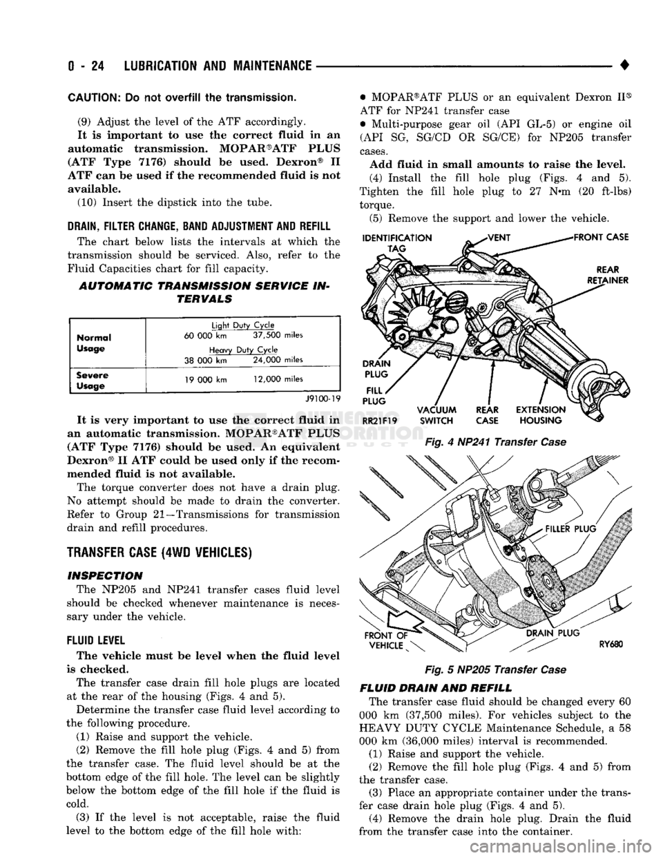
The transfer case drain fill hole plugs
are
located
at
the
rear
of the
housing (Figs.
4 and 5).
Determine
the
transfer case fluid level according
to
the following procedure.
(1) Raise
and
support
the
vehicle.
(2) Remove
the
fill hole plug (Figs.
4 and 5)
from
the transfer case.
The
fluid level should
be at the
bottom edge
of the
fill hole.
The
level
can be
slightly
below
the
bottom edge
of the
fill hole
if the
fluid
is
cold.
(3)
If the
level
is not
acceptable, raise
the
fluid
level
to the
bottom edge
of the
fill hole with: • MOPAR®ATF PLUS
or an
equivalent Dexron
II®
ATF
for
NP241 transfer case
• Multi-purpose gear
oil (API GL-5) or
engine
oil
(API
SG,
SG/CD
OR
SG/CE)
for
NP205 transfer
cases.
Add fluid
in
small amounts
to
raise
the
level. (4) Install
the
fill hole plug (Figs.
4 and 5).
Tighten
the
fill hole plug
to 27 N-m (20
ft-lbs) torque.
(5) Remove
the
support
and
lower
the
vehicle.
Fig.
4
HP241 Transfer
Case
Fig.
5
NP205 Transfer
Case
FLUID DRAIN
AND
REFILL The transfer case fluid should
be
changed every
60
000
km
(37,500 miles).
For
vehicles subject
to the
HEAVY DUTY CYCLE Maintenance Schedule,
a 58
000
km
(36,000 miles) interval
is
recommended.
(1) Raise
and
support
the
vehicle.
(2) Remove
the
fill hole plug (Figs.
4 and 5)
from
the transfer case. (3) Place
an
appropriate container under
the
trans
fer case drain hole plug (Figs.
4 and 5).
(4) Remove
the
drain hole plug. Drain
the
fluid
from
the
transfer case into
the
container.
Page 44 of 1502
•
LUBRICATION
AND
MAINTENANCE
0 - 25
CAUTION:
Do not
over-tighten
the
drain
and fill
hole
plugs.
Over-tightening
can strip the
hole
threads
and/or crack
the
aluminum housing.
(5) Install the drain hole plug (Figs. 4 and 5) in
the transfer case. Tighten the drain hole plug to 27 N*m (20 ft-lbs) torque. (6) Fill the transfer case to the bottom edge of the
fill hole (Figs. 4 and 5) with: • MOPAR®ATF PLUS or an equivalent Dexron II®
ATF for NP241 transfer cases
• Multi-purpose gear oil (API GL-5) or engine oil (API SG, SG/CD or SG/CE) for NP205 transfer cases. (7) Install the fill hole plug (Figs. 4 and 5) in the
transfer case. Tighten the plug to 27 N«m (20 ft-lbs) torque.
(8) Remove the support and lower the vehicle.
FLUID SPECIFICATION
• MOPAR®ATF PLUS or an equivalent Dexron II®
ATF for NP241 transfer cases • Multi-purpose gear oil (API GL-5) or engine oil (API SG, SG/CD or SG/CE) for NP205 transfer cases
NP20I
MULTI-PURPOSE GEAR OIL/ENGINE
OIL
SELECTION
MULTI-PURPOSE GEAR OIL-if the anticipated
minimum temperature will: • Be above 32°C (90°F)-use SAE 140, API GL-5;
• Decrease to as low as -23°C (-10°F)-use SAE 90,
API GL-5; and • Be below -23°C (-10°F)-use SAE 80, API GL-5. ENGINE OIL—if the anticipated minimum tem
perature will be: ® Above 0°C (32°F)-use SAE 50, API SG, SG/CD or
SG/CE;
• Below 0°C (32°F)-use SAE 30, API SG, SG/CD or SG/CE.
SHIFT MECHANISM-NP241 AND NP205 The transfer case shift mechanism should be
cleaned and lubricated as necessary.
Lubricate the pivot, the sliding contact areas and
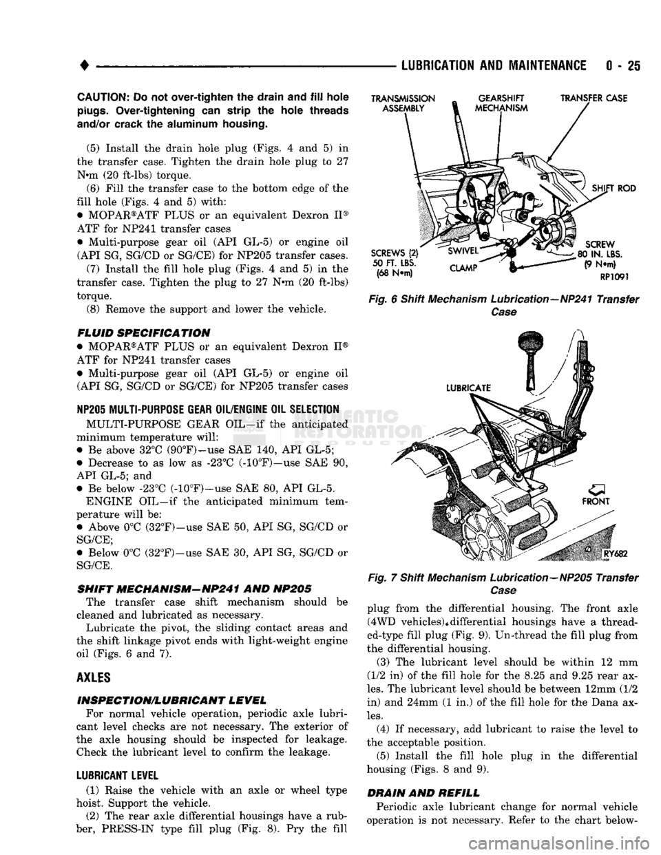
the shift linkage pivot ends with light-weight engine oil (Figs. 6 and 7).
AXLES
INSPECTION/LUBRICANT LEVEL For normal vehicle operation, periodic axle lubri
cant level checks are not necessary. The exterior of
the axle housing should be inspected for leakage. Check the lubricant level to confirm the leakage.
LUBRICANT LEVEL
(1) Raise the vehicle with an axle or wheel type
hoist. Support the vehicle.
(2) The rear axle differential housings have a rub
ber, PRESS-IN type fill plug (Fig. 8). Pry the fill
TRANSMISSION
ASSEMBLY
GEARSHIFT
MECHANISM TRANSFER CASE
SCREWS
(2)
50
FT. LBS.
(68 N*m)
CLAMP
SHIFT
ROD
SCREW
80 IN.
LBS.
(9 N*m)
RP1091
Fig.
6 Shift
Mechanism
Lubrication—NP241 Transfer
Case
Fig.
RY682
7 Shift
Mechanism
Lubrication—NP205 Transfer
Case
plug from the differential housing. The front axle (4WD vehicles)*differential housings have a thread
ed-type fill plug (Fig. 9). Un-thread the fill plug from
the differential housing.
(3) The lubricant level should be within 12 mm
(1/2 in) of the fill hole for the 8.25 and 9.25 rear ax
les.
The lubricant level should be between 12mm (1/2
in) and 24mm (1 in.) of the fill hole for the Dana ax
les.
(4) If necessary, add lubricant to raise the level to
the acceptable position.
(5) Install the fill hole plug in the differential
housing (Figs. 8 and 9).
DRAIN
AND
REFILL
Periodic axle lubricant change for normal vehicle
operation is not necessary. Refer to the chart below-
Page 189 of 1502
5 - 2 BRAKES
• CAUTION:
Never
use gasoline,
kerosene,
alcohol,
motor
oil, transmission
fluid,
or any
fluid
containing
mineral
oil to
clean
the system
components.
These
fluids
damage
rubber
cups and seals. If system
contamination
is suspected,
check
the
fluid
for
dirt,
discoloration,
or
separation
into
distinct
layers.
Drain
and
flush
the system
with
new
brake
fluid
if
contamination
is suspected.
BRAKE
SAFETY PRECAUTIONS WARNING: DUST AND DIRT ON BRAKE PARTS
THAT
ACCUMULATES DURING NORMAL USE MAY CONTAIN ASBESTOS FIBERS. BREATHING
EXCES
SIVE
CONCENTRATIONS OF ASBESTOS FIBERS
CAN
CAUSE SERIOUS BODILY HARM. EXERCISE
CARE
WHEN SERVICING BRAKE COMPONENTS.
DO NOT CLEAN BRAKE COMPONENTS
WITH
COM
PRESSED
AIR OR BY DRY BRUSHING. USE A VAC UUM CLEANER SPECIFICALLY DESIGNED FOR
REMOVING BRAKE DUST
THAT
MAY ASBESTOS
FIBERS.
IF A SUITABLE VACUUM CLEANER IS NOT
AVAILABLE,
CLEANING SHOULD BE DONE USING
A
WATER DAMPENED CLOTH. DO NOT CREATE DUST BY SANDING, GRINDING, OR SHAVING
BRAKE
LININGS UNLESS PROPERLY VENTED
EQUIPMENT IS USED. DISPOSE OF ALL DUST AND
DIRT
THAT
MAY CONTAIN ASBESTOS FIBERS IN
SEALED
BAGS OR CONTAINERS. THIS WILL MINI MIZE EXPOSURE TO YOURSELF AND OTHERS.
FOLLOW ALL RECOMMENDED PRACTICES PRE
SCRIBED
BY THE OCCUPATIONAL SAFETY AND HEALTH ADMINISTRATION AND THE ENVIRON
MENTAL PROTECTION AGENCY FOR THE HAN
DLING, PROCESSING, AND DISPOSITION OF DUST
OR DIRT WHICH MAY CONTAIN ASBESTOS FI
BERS.
Page 190 of 1502

•
BRAKES
i - 3 BRAKE DIAGNOSIS
INDEX
page
Brake
Warning Lights
3
Diagnosing
Brake Problems .................
4
Diagnosis
Procedures
3
Low
Vacuum
Switch—Diesel
Models
3
page
Master
Cylinder/Power Booster Test
5
Power
Booster
Check
Valve Test .............
6
Power
Booster
Vacuum
Test .................
6
Testing Diesel
Engine
Vacuum
Pump
Output
.... 6
DIAGNOSIS
PROCEDURES
Brake diagnosis involves determining
if the
prob
lem
is
related
to a
mechanical, hydraulic
or
vacuum
operated component.
A
preliminary check, road test
ing
and
component inspection
can all be
used
to de
termine
a
problem cause. Road testing will either verify proper brake opera
tion
or
confirm
the
existence
of a
problem. Compo nent inspection will,
in
most cases, identify
the
actual part causing
a
problem. The first diagnosis step
is the
preliminary check. This
involves inspecting fluid level, parking brake action,
wheel
and
tire condition, checking
for
obvious leaks
or
component damage
and
testing brake pedal response. A road test will confirm
the
existence
of a
problem.
Final diagnosis procedure involves road test analysis and
a
visual inspection
of
brake components.
BRAKE
WARNING LIGHTS
The
red
brake warning light
is
connected
to the
parking brake switch
and to the
pressure differential switch
in the
combination valve. The
red
light will illuminate when
the
parking
brakes
are
applied
or
when
a
fluid pressure drop
oc
curs
in the
front
or
rear brake circuit.
The
light will
also illuminate
for
approximately
2-4
seconds
at en
gine start
up.
This
is a
self test feature designed
to
check bulb
and
circuit operation each time
the en
gine
is
started. The amber antilock light
is
connected
to the
anti-
lock rear brake hydraulic valve.
The
light will illu
minate
if a
fault occurs within
the
antilock system.
LOW VACUUM SWITCH-DIESEL MODELS
On diesel models,
the red
brake warning light
is
also
used
to
alert
the
driver
of a low
brake booster vacuum
condition.
The
warning light
is in
circuit with
a
vacuum
warning switch mounted
on the
driver side fender
panel.
The
vacuum side
of the
switch
is
connected
to the
power brake booster.
The
electrical side
of the
switch
is
connected
to the
brake warning light. The
low
vacuum switch monitors booster vacuum
level whenever
the
engine
is
running.
If
booster vac
uum falls below
8.5
inches vacuum
for a
minimum
of
10 seconds,
the
switch completes
the
circuit
to the
warning light causing
it to
illuminate.
The
warning light
is
designed
to
differentiate between
a low
vac
uum condition
and a
hydraulic circuit fault.
PRELIMINARY
BRAKE CHECK
(1) Check condition
of
tires
and
wheels. Damaged
wheels
and
worn, damaged,
or
underinflated tires
can
cause pull, shudder, tramp,
and a
condition similar
to
grab.
(2)
If
complaint
was
based
on
noise when braking,
check suspension components. Jounce front
and
rear
of
vehicle
and
listen
for
noise that might
be
caused
by
loose, worn
or
damaged suspension
or
steering compo
nents.
(3) Inspect brake fluid level
and
condition. Note
that
the
front disc brake reservoir fluid level will drop
in
proportion
to
normal lining wear. Also note
that brake fluid tends
to
darken over time. This
is normal
and
should
not be
mistaken
for
con
tamination.
If the
fluid
is
still clear
and
free
of
foreign material,
it is OK.
(a)
If
fluid level
is
abnormally
low,
look
for
evi
dence
of
leaks
at
calipers, wheel cylinders, brake-
lines
and
master cylinder.
(b)
If
fluid appears contaminated, drain
out a
sample.
If
fluid
is
separated into layers,
or
obvi
ously contains
oil or a
substance other than brake
fluid,
the
system seals
and
cups will have
to be re
placed
and the
hydraulic system flushed.
(4) Check parking brake operation. Verify free
movement
and
full release
of
cables
and
pedal. Also
note
if
vehicle
was
being operated with parking
brake partially applied.
(5) Check brake pedal operation. Verify that pedal
does
not
bind
and has
adequate free play.
If
pedal
lacks free play, check pedal
and
power booster
for be
ing loose
or for
bind condition.
Do not
road test until
condition
is
corrected.
(6)
If
components checked appear
OK,
road test
the
vehicle.
ROAD
TESTING (1)
If
complaint involved
low
brake pedal, pump
the pedal
and
note
if the
pedal comes back
up to
nor mal height.
(2) Check brake pedal response with transmission
in Neutral
and
engine running. Pedal should remain
firm under steady foot pressure.
Page 191 of 1502
5
- 4
BRAKES
• (3) During road test, make normal and firm brake
stops in 25-40 mph (40-64 Km/h) range. Note faulty
brake operation such as pull, grab, drag, noise, low
pedal, etc.
(4) Inspect suspect brake components and refer to
problem diagnosis information for causes of various
brake conditions.
COMPONENT
INSPECTION
Fluid leak points and dragging brake units can usu
ally be located without removing any components. The
area around a leak point will be wet with fluid. The
components at a dragging brake unit (wheel, tire, rotor)
will be quite warm or hot to the touch.
Other brake problem conditions will require compo
nent removal for proper inspection. Raise the vehicle and remove the necessary wheels for better visual ac
cess.
DIAGNOSING BRAKE
PROBLEMS
PEDAL FALLS
AWAY
A
brake pedal that falls away under steady foot
pressure is the result of a system leak. The leak
point could be at a brakeline, fitting, hose, or caliper. Internal leakage in the master cylinder caused by
worn or damaged piston cups, may also be the prob lem cause.
If leakage is severe, fluid will be evident at or around
the leaking component. However, internal leakage in
the master cylinder may not be physically evident. Re fer to the cylinder test procedure in this section.
LOW PEDAL
If a low pedal is experienced, pump the pedal sev
eral times. If the pedal comes back up, worn lining
and worn rotors or drums are the likely causes.
A decrease in fluid level in the master cylinder res
ervoirs may only be the result of normal lining wear.
Fluid level can be expected to decrease in proportion to wear. It is a result of the outward movement of
caliper and wheel cylinder pistons to compensate for
normal wear. Top off the reservoir fluid level and
check brake operation to verify proper brake action.
SPONGY PEDAL. A spongy pedal is most often caused by air in the sys
tem. Thin brake drums or substandard brake lines and
hoses can also cause a spongy pedal. The proper course
of action is to bleed the system and replace thin drums and suspect quality brake lines and hoses.
HARD PEDAL
OR
HIGH
PEDAL
EFFORT
A hard pedal or high pedal effort may be due to
lining that is water soaked, contaminated, glazed, or
badly worn. The power booster or check valve could also be faulty. On diesel engine models, high pedal effort may be
the result of a low vacuum condition. If the booster and check valve are OK, the problem may be related
to a vacuum pump hose, hose connection, hose fit
ting, pump diaphragm, or drive gear. Vacuum pump output can be checked with a standard vacuum
gauge. Vacuum output should range from 8.5 to 25 inches vacuum. If vacuum pump output is within
limits,
check the power booster and check valve as
described in this section.
BRAKE DRAG
Brake drag occurs when the lining is in constant
contact with the rotor or drum. Drag can occur at
one wheel, all wheels, fronts only, or rears only. It is a product of incomplete brakeshoe release. Drag can
be minor or severe enough to overheat the linings,
rotors and drums.
Brake drag can also effect fuel economy. If undetec
ted, minor brake drag can be misdiagnosed as an en gine or transmission/torque converter problem.
Minor drag will usually cause slight surface charring
of the lining. It can also generate hard spots in rotors and drums from the overheat-cool down process. In most
cases,
the rotors, drums, wheels and tires are quite
warm to the touch after the vehicle is stopped.
Severe drag can char the brake lining all the way
through. It can also distort and score rotors and drums to the point of replacement. The wheels, tires and brake components will be extremely hot. In se
vere cases, the lining may generate smoke as it chars
from overheating.
Some common causes of brake drag are:
• seized or improperly adjusted parking brake cables
• loose/worn wheel bearing
• seized caliper or wheel cylinder piston
• caliper binding on corroded bushings or rusted
slide surfaces
• loose caliper mounting bracket
• drum brakeshoes binding on worn or damaged sup
port plates
• misassembled components. If brake drag occurs at all wheels, the problem may
be related to a blocked master cylinder return port, or faulty power booster that binds and does not release.
BRAKE FADE
Brake fade is a product of overheating caused by
brake drag. However, brake overheating and subse quent fade can also be caused by riding the brake
pedal, making repeated high deceleration stops in a short time span, or constant braking on steep moun
tain roads. Refer to the Brake Drag information in
this section for additional causes.
PEDAL
PULSA
TION
Pedal pulsation is caused by components that are
loose, out of round, or worn beyond tolerance limits.
Page 192 of 1502

•
BRAKES
5 - 5 Disc brake rotors with excessive lateral runout or
thickness variation, or out of round brake drums are
the primary causes of pulsation. Other causes are loose
wheel bearings or calipers and worn, damaged tires.
PULL A
front pull condition could be the result of con
taminated lining in one caliper, seized caliper piston,
binding caliper, loose caliper, loose or corroded slide
pins,
improper brakeshoes, or a damaged rotor.
A worn, damaged wheel bearing or suspension compo
nent are further causes of pull. A damaged front tire (bruised, ply separation) can also cause pull.
A common and frequently misdiagnosed pull condi
tion is where direction of pull changes after a few
stops.
The cause is a combination of brake drag fol
lowed by fade at one of the brake units.
As the dragging brake overheats, efficiency is so
reduced that fade occurs. Since the opposite brake
unit is still functioning normally, its braking effect is
magnified. This causes pull to switch direction in fa
vor of the normally functioning brake unit.
When diagnosing a change in pull condition, re
member that pull will return to the original direction
if the dragging brake unit is allowed to cool down (and is not seriously damaged).
REAR BRAKE GRAB
OR
PULL
Rear grab or pull is usually caused by an improperly
adjusted or seized parking brake cable, contaminated
lining, bent or binding shoes and support plates, or im
properly assembled components. This is particularly
true when only one rear wheel is involved. However,
when both rear wheels are affected, the master cylinder or proportioning valve could be at fault.
BRAKES
DO NOT
HOLD
AFTER
DRIVING
THROUGH
DEEP
WATER
PUDDLES
This condition is generally caused by water soaked
lining. If the lining is only wet, it can be dried by driv
ing with the brakes very lightly applied for a few min
utes.
However, if the lining is thoroughly wet and dirty,
disassembly and cleaning will be necessary.
BRAKE NOISE
Squeak/Squeal
Brake squeak or squeal may be due to linings that
are wet or contaminated with brake fluid, grease, or oil. Glazed linings and rotors with hard spots can also con
tribute to squeak. Dirt and foreign material embedded in the brake lining can also cause squeak/squeal.
A very loud squeak or squeal is frequently a sign of
severely worn brake lining. If the lining has worn
through to the brakeshoes in spots, metal-to-metal con
tact occurs. If the condition is allowed to continue, ro tors can become so scored that replacement is necessary.
Thump/Clunk
Thumping or clunk noises during braking are fre
quently not caused by brake components. In many
cases,
such noises are caused by loose or damaged steering, suspension, or engine components. How
ever, calipers that bind on the slide pins, or slide sur
faces,
can generate a thump or clunk noise. Worn
out, improperly adjusted, or improperly assembled
rear brakeshoes can also produce a thump noise.
Chatter
Brake chatter is usually caused by loose or worn
components, or glazed/burnt lining. Rotors with hard
spots can also contribute to chatter. Additional
causes of chatter are out of tolerance rotors, brake
lining not securely attached to the shoes, loose wheel
bearings and contaminated brake lining.
Brakelining Contamination Brakelining contamination is usually a product of
leaking calipers or wheel cylinders, driving through
deep water puddles, or lining that has become cov
ered with grease and grit during repair.
Wheel and
Tire
Problems Some conditions attributed to brake components
may actually be caused by a wheel or tire problem.
A damaged wheel can cause shudder, vibration and
pull. A worn or damaged tire can also cause pull.
Severely worn tires with very little tread left can
produce a grab-like condition as the tire loses and re covers traction. Flat-spotted tires can cause vibration and wheel
tramp and generate shudder during brake operation. A tire with internal damage such as a severe
bruise or ply separation can cause pull and vibration.
MASTER
CYLINDER/POWER BOOSTER TEST
(1) Start engine and check booster vacuum hose
connections. Hissing noise indicates a vacuum leak. Correct any leaks before proceeding. (2) Stop engine and shift transmission into Neu
tral (3) Pump brake pedal until all vacuum reserve in
booster is depleted. (4) Press and hold brake pedal under light foot
pressure. (a) If pedal holds firm, proceed to step (5).
(b) If pedal does not hold firm and falls away,
master cylinder is faulty (internal leakage). (5) Start engine and note pedal action. (a) If pedal falls away slightly under light foot
pressure then holds firm, proceed to step (6). (b) If pedal is effort is high, or no pedal action is
discernible, power booster or vacuum check valve is
faulty. Install known good check valve and repeat steps (2) through (5).
Page 255 of 1502
6
- 2
CLUTCH
•
CLUTCH DIAGNOSIS
INDEX
page
Clutch Problem
Causes
, 2
General
Diagnosis
Information
2
GENERAL
DIAGNOSIS INFORMATION
Unless the cause of a clutch problem is obvious, a
road test and component inspection will be required
for accurate diagnosis. A road test will help determine the type of fault
while component inspection will identify the problem component. During a road test, drive the vehicle at normal
speeds. Shift the transmission through all gear
ranges and observe clutch action. If chatter, grab, slip, or improper release is experi
enced, remove and inspect the clutch components.
However, if the problem is noise or hard shifting,
further diagnosis is needed. The transmission or an
other driveline component may actually be at fault. Careful observation during a road test will help
narrow the problem area.
CLUTCH PROBLEM
CAUSES
CONTAMINATION Fluid contamination is one of the more common
causes of clutch malfunctions. Oil, water, or clutch
fluid on the clutch contact surfaces will result in
faulty operation. The usual result is chatter, slip, or
grab.
During inspection, note if any components are con
taminated with oil, hydraulic fluid, or water/road splash.
Oil contamination indicates a leak at either the
rear main seal or transmission input shaft.
Oil leakage produces a residue of oil on the hous
ing interior and on the clutch cover and flywheel.
Heat buildup caused by slippage between the cover,
disc and flywheel, can sometimes bake the oil residue
onto the components. The glaze-like residue ranges
in color from amber to black.
Road splash contamination means dirt and water
are entering the clutch housing due to loose bolts,
housing cracks, vent openings, or through the slave
cylinder opening. Driving through deep water pud
dles can force water/road splash into the housing
through such openings.
An additional problem caused by water contamina
tion and especially by steam cleaning, involves
clutch disc sticking and poor release. Water and steam vapors can be absorbed by the
clutch facing material. If the vehicle sits idle for long
page
Inspection
and
Diagnosis
Charts 5
periods after water contamination, the force exerted
by the pressure plate may cause the disc to bond it self to the flywheel or pressure plate.
Frequently, the only remedy for the above condi
tion is component replacement. To avoid this prob
lem, a vehicle should be driven as soon as possible to
heat and dry the clutch components.
Clutch fluid leaks are from a loose or damaged
slave cylinder line or connection. However, clutch
fluid leaks will usually be noted and corrected before severe contamination occurs.
CLUTCH MISALIGNMENT
Clutch components must be in proper alignment
with the crankshaft and transmission input shaft.
Misalignment caused by excessive runout or warpage of any clutch component will cause grab, chatter and improper clutch release.
Flywheel
Runout
Common causes of runout are heat warping, im
proper machining, mounting the flywheel on a dirty crankshaft flange, incorrect bolt tightening, or im
proper seating on the crankshaft flange shoulder.
Very light scratches or surface roughness on the
flywheel face can be cleaned up by scuff sanding with 180 grit emery cloth. However, if the surface is
warped or severely scored, replace the flywheel.
Do not machine the flywheel. The flywheel
face is manufactured with a unique surface con
tour. Machining would negate this feature and could result in unsatisfactory operation.
Clean the crankshaft flange before mounting the
flywheel. Dirt and grease on the flange surface may cock the flywheel causing runout.
Use new bolts when remounting a flywheel and se
cure the bolts with Mopar Lock And Seal, or Loctite
242.
Tighten flywheel bolts to specified torque only.
Overtightening could distort the flywheel hub caus
ing runout.
Clutch
Cover
And Disc
Runout
Check the clutch disc before installation. Axial
(face) runout of a new disc should not exceed 0.5 mm
(0.020 in.). Measure runout about 6 mm (1/4 in.)
from the outer edge of the disc facing. Obtain an other disc if runout is excessive.