1993 DODGE TRUCK catalytic converter
[x] Cancel search: catalytic converterPage 21 of 1502
0 - 2
LUBRICATION
AND
MAINTENANCE
• Commercial service
When a vehicle is continuously subjected to severe
driving conditions, lubricate:
• Body components
• All the driveline coupling joints
• Steering linkage More often than normal driving conditions
DUSTY
AREAS
With this type of severe driving condition, special
care should be given to the:
• Engine air cleaner filter
• PCV filter
• Crankcase ventilation system
• Brake booster control valve air filter. Verify that the filters and the associated compo
nents are clean. Also verify that they are functioning
effectively. This will minimize the amount of abra sive particles that enter the engine.
OFF-ROAD
(4WD)
OPERATION
After off-road (4WD) operation, inspect the under
side of the vehicle. Inspect the:
• Tires
• Body structure
• Steering components
• Suspension components • Exhaust system
• Threaded fasteners
HARSH
SURFACE ENVIRONMENTS
After extended operation in harsh environments,
the brake drums, brake linings, and rear wheel bear ings should be inspected and cleaned. This will pre
vent wear and erratic brake action.
ROUTINE MAINTENANCE
The following routine maintenance is recommended
on a monthly basis: TIRES—Inspect the tires for unusual wear/damage.
Determine if the inflation pressure is adequate for
the vehicle load. BATTERY—Inspect and clean the terminals.
Tighten the terminals if necessary. FLUIDS—Determine if the component fluid levels
are acceptable. Add fluid, if necessary. LIGHTS/ELECTRICAL—Test all the electrical sys
tems in the vehicle for proper operation. It is also recommended that the engine oil and the
washer fluid level be determined at each fuel fill-up.
VEHICLE
NOISE CONTROL
Vehicles with a GVWR of 4 535 kg (10,000 lbs), or
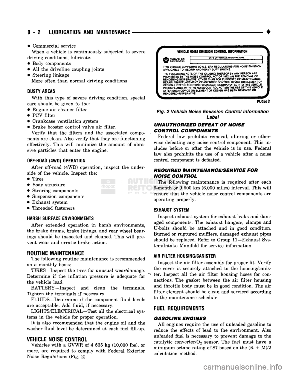
more, are required to comply with Federal Exterior Noise Regulations (Fig. 2).
VEHICLE
NOISE
EMISSION
CONTROL INFORMATION
DATE
OF
VEHICLE
MANUFACTURE
THIS
VEHICLE CONFORMS
TO
U.S. EPA REGULATIONS FOR NOISE EMISSION
APPLICABLE
TO
MEDIUM
AND HEAVY
DUTY
TRUCKS. THE
FOLLOWING
ACTS OR THE CAUSING THEREOF BY ANY PERSON ARE PROHIBITED BY THE NOISE CONTROL ACT
OF 1972. (A) THE
REMOVAL
OR
RENDERING
INOPERATIVE, OTHER
THAN
FOR
PURPOSES
OF
MAINTENANCE,
REPAIR.
OR REPLACEMENT, OF ANY NOISE CONTROL DEVICE OR ELEMENT OF
DESIGN
(LISTED
IN
THE
OWNERS
MANUAL)
INCORPORATED
INTO
THIS
VEHICLE
IN COMPLIANCE
WITH
THE NOISE CONTROL
ACT:
(B) THE
USE
OF
THIS
VEHICLE
AFTER SUCH DEVICE
OR
ELEMENT
OF
DESIGN HAS BEEN REMOVED
OR
RENDERED
INOPERATIVE.
PU626D
Fig.
2 Vehicle
Noise
Emission
Control Information
Label
UNAUTHORIZED
DEFEAT
OF
NOISE
CONTROL COMPONENTS
Federal law prohibits removal, altering or other
wise defeating any noise control component. This in
cludes before or after the vehicle is in use. Federal
law also prohibits the use of a vehicle after a noise
control component is defeated.
REQUIRED MAINTENANCE/SERVICE
FOR
NOISE
CONTROL
The following maintenance is required after each
6-month or 9 600 km (6,000 miles) interval. This will
ensure that the vehicle noise control components are
operating properly.
EXHAUST SYSTEM
Inspect exhaust system for exhaust leaks and dam
aged components. The exhaust hangers, clamps and
U-bolts should be attached and in good condition.
Burned or ruptured mufflers, damaged exhaust pipes should be replaced. Refer to Group 11—Exhaust Sys
tem/Intake Manifold for service information.
AIR
FILTER
HOUSING/CANISTER
Inspect the air filter assembly for proper fit. Verify
the cover is securely attached to the housing/canis
ter. Inspect all the air filter housing hoses for con nections. The gasket between the air filter housing and throttle body must be in good condition. The air
filter element should be clean and serviced according
to the maintenance schedule.
FUEL
REQUIREMENTS
GASOLINE
ENGINES
All engines require the use of unleaded gasoline to
reduce the effects of lead to the environment. Also unleaded fuel is necessary to prevent damage to the
catalytic converter/02 sensor. The fuel must have a
minimum octane rating of 87 based on the (R + M)/2
calculation method.
Page 28 of 1502
•
LUBRICATION AND MAINTENANCE
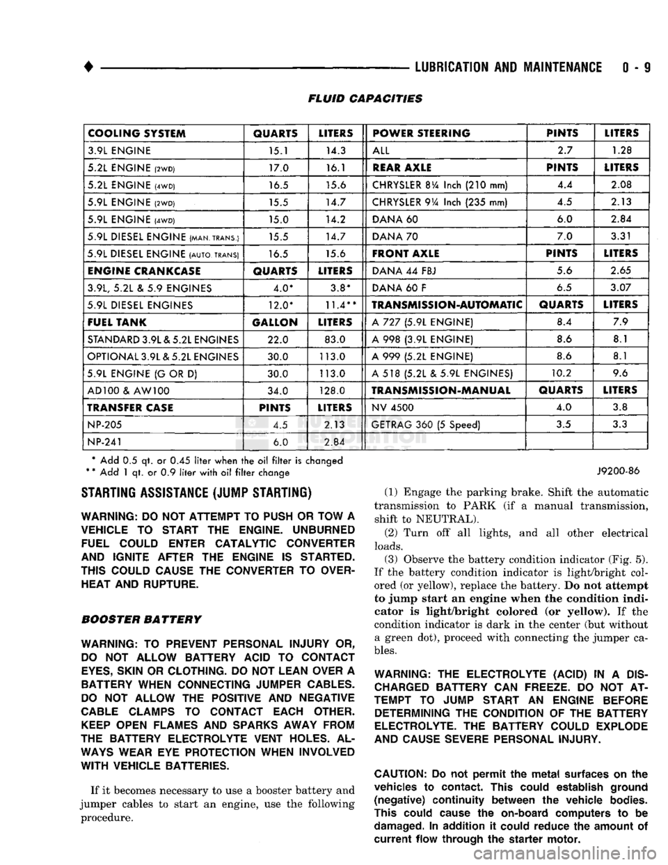
0 - 9 FLUID CAPACITIES
COOLING SYSTEM
QUARTS
LITERS
POWER STEERING PINTS
LITERS
3.9L ENGINE 15.1 14.3
ALL
2.7
1.28
5.2L ENGINE
(2WD)
17.0 16.1
REAR
AXLE
PINTS
LITERS
5.2L ENGINE
(4WD)
16.5 15.6
CHRYSLER
BVa
Inch
(210
mm) 4.4
2.08
5.9L ENGINE
(2WD)
15.5 14.7
CHRYSLER
9Va
Inch
(235
mm) 4.5
2.13
5.9L ENGINE
(4WD)
15.0 14.2
DANA
60 6.0
2.84
5.9L DIESEL ENGINE (MAN.TRANS.) 15.5 14.7
DANA
70 7.0
3.31
5.9L DIESEL ENGINE
(AUTO,
TRANS)
16.5 15.6
FRONT AXLE
PINTS
LITERS
ENGINE
CRANKCASE
QUARTS
LITERS
DANA
44
FBJ 5.6
2.65
3.9L,
5.2L & 5.9
ENGINES 4.0* 3.8*
DANA
60 F
6.5
3.07
5.9L DIESEL ENGINES 12.0*
11.4**
TRANSMISSION-AUTOMATIC
QUARTS
LITERS
FUEL TANK GALLON
LITERS
A
727 (5.9L
ENGINE) 8.4
7.9
STANDARD
3.9L & 5.2L ENGINES 22.0 83.0
A
998 (3.9L
ENGINE) 8.6
8.1
OPTIONAL 3.9L & 5.2L ENGINES 30.0 113.0
A
999 (5.2L
ENGINE) 8.6
8.1
5.9L ENGINE
{G
OR
D)
30.0 113.0
A
518 (5.2L & 5.9L
ENGINES) 10.2
9.6
AD 100
&
AW 100 34.0 128.0
TRANSMISSION-MANUAL
QUARTS
LITERS
TRANSFER
CASE
PINTS
LITERS
NV
4500
4.0
3.8
NP-205
4.5 2.13
GETRAG
360 (5
Speed)
3.5
3.3
NP-241
6.0
2.84
* Add
0.5 qt. or 0.45
liter
when
the oil filter
is
changed
*
*
Add
1 qt. or 0.9
liter
with
oil filter
change STARTING ASSISTANCE (JUMP STARTING)
WARNING:
DO NOT
ATTEMPT
TO
PUSH
OR
TOW
A
VEHICLE
TO
START
THE
ENGINE. UNBURNED FUEL COULD ENTER CATALYTIC CONVERTER
AND IGNITE AFTER
THE
ENGINE
IS
STARTED.
THIS COULD CAUSE
THE
CONVERTER
TO
OVER HEAT AND RUPTURE.
BOOSTER BATTERY
WARNING:
TO
PREVENT PERSONAL INJURY
OR,
DO
NOT
ALLOW BATTERY ACID
TO
CONTACT
EYES,
SKIN
OR
CLOTHING.
DO NOT
LEAN OVER
A
BATTERY WHEN CONNECTING JUMPER
CABLES.
DO
NOT
ALLOW
THE
POSITIVE
AND
NEGATIVE
CABLE
CLAMPS
TO
CONTACT EACH OTHER.
KEEP
OPEN FLAMES
AND
SPARKS
AWAY FROM
THE BATTERY ELECTROLYTE VENT HOLES.
AL
WAYS
WEAR
EYE
PROTECTION WHEN INVOLVED
WITH
VEHICLE BATTERIES.
If it becomes necessary to use a booster battery and
jumper cables to start an engine, use the following procedure.
J9200-86
(1) Engage the parking brake. Shift the automatic
transmission to PARK (if a manual transmission, shift to NEUTRAL).
(2) Turn off all lights, and all other electrical
loads.
(3)
Observe the battery condition indicator (Fig. 5).
If the battery condition indicator is light/bright col
ored (or yellow), replace the battery. Do not attempt
to jump start an engine when the condition indi
cator is light/bright colored (or yellow). If the
condition indicator is dark in the center (but without a green dot), proceed with connecting the jumper ca
bles.
WARNING:
THE
ELECTROLYTE (ACID)
IN A
DIS
CHARGED
BATTERY
CAN
FREEZE.
DO NOT AT
TEMPT
TO
JUMP START
AN
ENGINE BEFORE DETERMINING
THE
CONDITION
OF THE
BATTERY
ELECTROLYTE.
THE
BATTERY COULD EXPLODE
AND CAUSE SEVERE PERSONAL INJURY.
CAUTION:
Do not
permit
the
metal
surfaces
on the
vehicles
to
contact.
This
could
establish
ground
(negative)
continuity
between
the
vehicle
bodies.
This
could
cause
the
on-board
computers
to be
damaged.
In
addition
it
could
reduce
the
amount
of
current
flow
through
the
starter
motor.
Page 40 of 1502
•
LUBRICATION
AND
MAINTENANCE
0 - 21 ROUTINE INSPECTION
It is recommended that the drive belt(s) be rou
tinely inspected for cracks, fraying and excessive
wear. Replace as necessary.
EXHAUST SYSTEM
An exhaust system must be properly aligned to
prevent stress, leakage, and vehicle body contact.
MAINTENANCE SCHEDULE Inspect the exhaust system at the interval specified
in maintenance schedule.
INSPECTION Inspect for cracked or loose joints, corrosion dam
age,
and worn or broken hangers. Replace all compo
nents that are damaged. Do not attempt repair. Also,
inspect for the following conditions and correct as
necessary:
• Exhaust system leaks, misalignment • Contact with body panels or the frame
• Catalytic converter bulging or excessive heat dam
age
CAUTION:
A
catalytic converter
will
become
con
taminated
if
leaded gasoline
is
burned
in the en
gine.
If
this
occurs,
the
complete converter must
be
replaced.
AIR-CONDITIONER COMPRESSOR LUBRICANT
AND
REFRIGERANT
The lubricant level in the compressor should be
checked if there are indications that oil was lost.
Loss of lubricating oil usually accompanies a loss of
refrigerant. The presence of bubbles in sight glass in dicates that loss of refrigerant has occurred. For additional information involving the A/C sys
tem, refer to Group 24—Heater And Air Condition ing.
Page 275 of 1502
DIAGNOSIS
PRELIMINARY
CHECKS
ENGINE COOLING SYSTEM OVERHEATING Establish what driving conditions caused the com
plaint. Abnormal loads on the cooling system such as
the following may be the cause:
1.
PROLONGED IDLE, VERY HIGH AMBI
ENT TEMPERATURE, SLIGHT TAIL WIND AT
IDLE, SLOW TRAFFIC, TRAFFIC JAMS, HIGH SPEED OR STEEP GRADES.
Driving techniques that avoid overheating are:
• Idle with A/C off when temperature gauge is at
end of normal range. * Increasing engine speed for more air flow is recom
mended.
2.
TRAILER TOWING: Consult Trailer Towing section of owners manual.
Do not exceed limits.
3.
AIR CONDITIONING; ADD-ON OR AFTER
MARKET: A maximum cooling package should have been or
dered with vehicle if add-on or after market A/C is
SYMPTOM AND ACTION
SYMPTOM
installed. If not, maximum cooling system compo
nents should be installed for model involved per
manufacturer's specifications.
4.
RECENT SERVICE OR ACCIDENT RE
PAIR:
Determine if any recent service has been performed
on vehicle that may effect cooling system. This may
be:
• Engine adjustments (incorrect timing)
• Slipping engine accessory drive belt(s) • Brakes (possibly dragging)
• Changed parts. Incorrect water pump or pump ro
tating in wrong direction due to belt not correctly
routed
• Reconditioned radiator or cooling system refilling (possibly under filled or air trapped in system).
If investigation reveals none of the above as a
cause for an engine overheating complaint, refer to
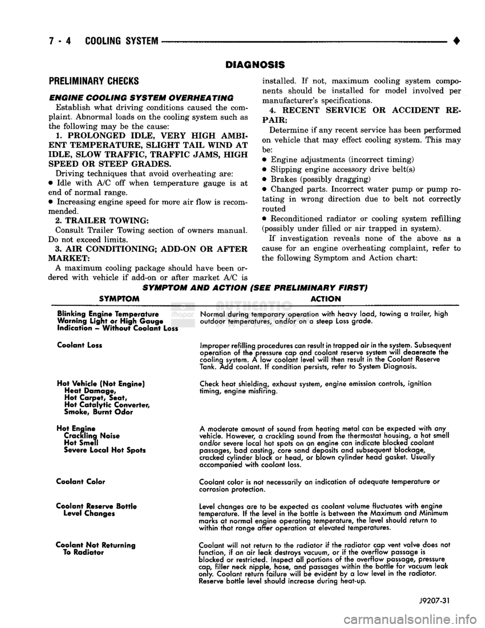
the following Symptom and Action chart:
PRELIMINARY FIRST) ACTION
Blinking Engine Temperature
Warning Light or High Gauge indication - Without Coolant Loss
Normal during temporary operation
with
heavy load, towing
a
trailer,
high
outdoor temperatures, and/or on
a
steep
Loss
grade.
Coolant Loss
Hot Vehicle (Not Engine) Heat Damage,
Hot Carpet, Seat,
Hot
Catalytic
Converter,
Smoke, Burnt Odor
Hot Engine Crackling Noise Hot Smell
Severe Local Hot Spots
Coolant Color
Coolant Reserve Bottle Level Changes
Coolant Not Returning To Radiator
Improper refilling procedures
can
result
in
trapped air
in
the
system.
Subsequent
operation
of the
pressure cap and coolant reserve system
will
deaereate
the
cooling
system.
A low
coolant
level
will
then result
in the
Coolant Reserve
Tank. Add coolant.
If
condition persists,
refer
to
System
Diagnosis.
Check
heat shielding, exhaust
system,
engine emission controls, ignition
timing, engine misfiring.
A
moderate amount
of
sound from heating
metal
can
be
expected
with
any
vehicle. However,
a
crackling sound from
trie
thermostat
housing,
a hot
smell and/or severe local
hot
spots on
an
engine can indicate blocked coolant
passages,
bad castina, core sand deposits and subsequent blockage,
cracked cylinder block
or
head,
or
blown cylinder head gasket. Usually
accompanied
with
coolant
loss.
Coolant
color is
not
necessarily
an
indication
of
adequate
temperature
or
corrosion
protection.
Level changes
are to be
expected as coolant volume fluctuates
with
engine
temperature.
If the
level
in the
bottle
is
between
the
Maximum and Minimum
marks
at
normal engine operating temperature,
the
level
should
return
to
within
that
range
after
operation
at
elevated temperatures.
Coolant
will
not
return
to the
radiator
if the
radiator cap vent valve does
not
function,
if
an
air
leak destroys vacuum,
or if the
overflow
passage
is
blocked
or
restricted. Inspect
all
portions
of the
overflow
passage,
pressure
cap,
filler
neck nipple, hose, and
passages
within
the
bottle
for
vacuum leak
only. Coolant
return
failure
will
be
evident
by a low
level
in the
radiator.
Reserve
bottle
level
should increase during heat-up.
J9207-31
Page 279 of 1502
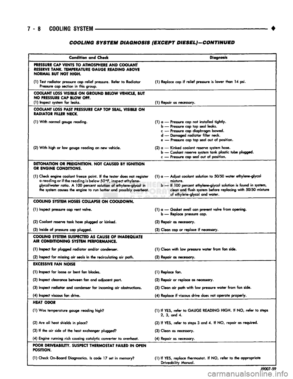
7 - 8
COOLING
SYSTEM
COOLING SYSTEM DIAGNOSIS (EXCEPT DIESEL)—CONTINUED
Condition and Check
Diagnosis
PRESSURE
CAP
VENTS
TO
ATMOSPHERE
AND COOLANT
RESERVE
TANK.
TEMPERATURE
GAUGE
READING
ABOVE
NORMAL
BUT NOT HIGH.
(1) Test radiator pressure cap
relief
pressure. Refer to Radiator Pressure cap section in this group. (1) Replace cap if
relief
pressure is lower than 14 psi.
COOLANT
LOSS
VISIBLE
ON
GROUND
BELOW
VEHICLE,
BUT
NO
PRESSURE
CAP
BLOW
OFF.
(1) Inspect
system
for leaks. (1) Repair as necessary.
COOLANT
LOSS
PAST
PRESSURE
CAP
TOP
SEAL,
VISIBLE
ON
RADIATOR
FILLER
NECK.
(1) With normal gauge reading. (1) a — Pressure cap not installed tightly.
b — Pressure cap top seal leaks.
c
— Pressure cap diaphragm bowed.
d — Damaged radiator
filler
neck.
e — Pressure cap top seal out of position.
(2) With high or low gauge reading on new vehicle. (2) a — Kinked coolant reserve
system
hose.
b — Coolant reserve
system
tank
plastic
tube
plugged,
c
— Pressure cap seal out of position.
DETONATION
OR
PREIGNITION.
NOT
CAUSED
BY IGNITION
OR
ENGINE
CONDITIONS.
(1) Check engine coolant
freeze
point. If the
tester
does
not register a reading or if
the
reading
is
below
50°F,
inspect
ethylene-
glycol/water
ratio.
A 100
percent
solution of ethylene-glycol in
the
system
causes
the engine to run
hotter
and
possibly
overheat. (1) a — Adjust coolant solution to
50/50
water
ethylene-glycol
mixture.
b — If 100
percent
ethylene-glycol solution
is
found in system, clean and flush
system
before
replacing
with
50/50
mixture
of ethylene-glycol and
water.
COOLING
SYSTEM
HOSES
COLLAPSE
ON
COOLDOWN.
(1) Inspect pressure cap
vent
valve. (1) a — Gasket swell can
prevent
valve from opening,
b — Replace pressure cap.
(2) Coolant reserve
tank
hose plugged or kinked. (2) Repair as necessary.
(3) Inside of pressure cap plugged. (3) Clean cap or replace if necessary.
COOLING
SYSTEM
SUSPECTED
AS
CAUSE
OF
INADEQUATE
AIR
CONDITIONING
SYSTEM
PERFORMANCE.
(1) Inspect for plugged radiator and/or condenser. (1) Clean
with
low pressure
water
from fan side.
(2) Inspect for
missing
air
seals
in the recirculating air path. (2) Repair as necessary.
EXCESSIVE
FAN
NOISE
(1) Inspect for loose or
bent
fan blades. (1) Replace fan.
(2) Inspect clearance
between
fan and adjacent
part.
(2) Repair or replace as necessary.
(3) Inspect radiator and condenser for incoming air obstructions. (3) Clean air path
with
low pressure
water
from fan side.
(4) Inspect
viscous
fan drive. (4) Replace if
viscous
drive
does not
operate
properly.
HEAT
ODOR
(1) Was
temperature
gauge reading
high?
(1) If
YES,
refer
to
GAUGE
READING
HIGH. If NO,
refer
to steps
2, 3, and 4.
(2) Are all
heat
shields in place? (2) If
YES,
refer
to
steps
3 and 4. If NO,
repair
as required.
(3) If the air side of the
heat
exchanger
plugged?
(3) Clean as necessary.
(4) Engine running rich
causing
catalytic converter to overheat. (4) Repair as necessary.
POOR
DRIVEABIUTY.
SUSPECT
THERMOSTAT
FAILED
IN
OPEN
POSITION.
(1) Check On-Board
Diagnostics.
Is code 17 set in memory? (1) If
YES,
replace thermostat. If NO,
refer
to the appropriate
Driveability Manual.
J9007-59
Page 284 of 1502
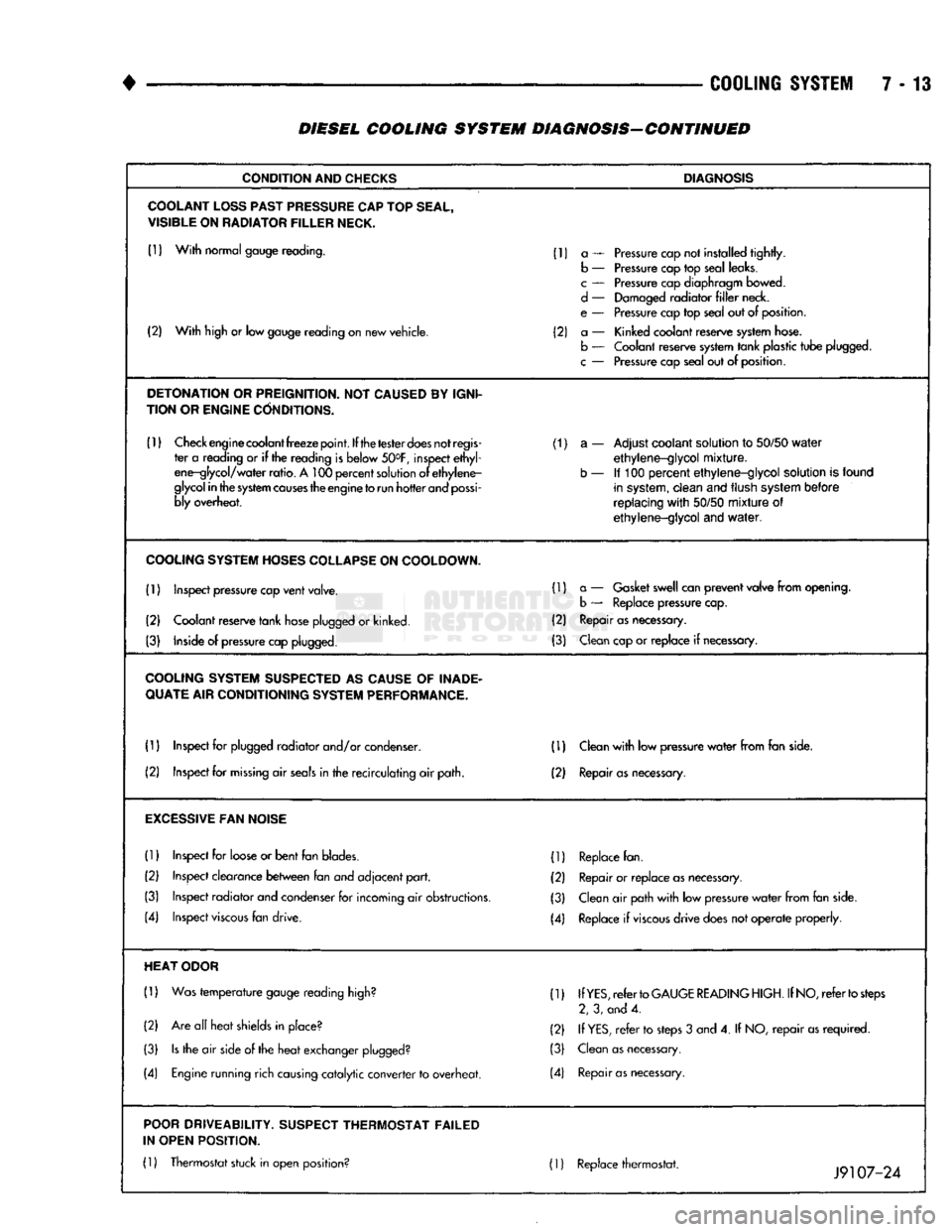
•
COOLING SYSTEM 7-13
DIESEL COOLING SYSTEM DIAGNOSIS-CONTINUED
CONDITION
AND
CHECKS
DIAGNOSIS
COOLANT
LOSS
PAST
PRESSURE
CAP
TOP
SEAL,
VISIBLE
ON
RADIATOR
FILLER
NECK.
(1)
With
normal gauge reading. (1) a — Pressure cap not installed
tightly.
b — Pressure cap top seal leaks.
c
— Pressure cap diaphragm bowed.
d
— Damaged
radiator
filler
neck.
e — Pressure cap top seal out of position.
(2)
With
high or low gauge reading on new vehicle. (2) a — Kinked coolant reserve system hose.
(2)
With
high or low gauge reading on new vehicle.
b — Coolant reserve system
tank
plastic
tube
plugged.
c
— Pressure cap seal out of position.
DETONATION
OR
PREIGNITION.
NOT
CAUSED
BY
IGNI
TION OR
ENGINE
CONDITIONS.
(1)
Check engine coolant
freeze
point.
If the
tester
does
not
regis
(1) a — Adjust coolant solution to
50/50
water
ter a reading or if the reading is below 50°F, inspect
ethyl
ethylene-glycol
mixture.
ene-glycol/
water
ratio.
A 100
percent
solution of
ethylene-
b — If 100
percent
ethylene-glycol
solution is found
glycol
in
the
system
causes
the engine
to
run
hotter
and
possi
in system,
clean
and flush system
before
bly overheat.
replacing
with
50/50
mixture
of
ethylene-glycol
and
water.
COOLING
SYSTEM
HOSES
COLLAPSE
ON
COOLDOWN.
(1) Inspect pressure cap
vent
valve. (1) a — Gasket swell can
prevent
valve
from
opening.
b — Replace pressure cap.
(2) Coolant reserve
tank
hose plugged or kinked. (2) Repair as necessary.
(3) Inside of pressure cap plugged. (3) Clean cap or
replace
if necessary.
COOLING
SYSTEM
SUSPECTED
AS
CAUSE
OF
INADE
QUATE
AIR CONDITIONING
SYSTEM
PERFORMANCE.
(1) Inspect for plugged
radiator
and/or condenser. (D Clean
with
low pressure
water
from
fan side.
(2) Inspect for
missing
air
seals
in the
recirculating
air path. (2) Repair
as
necessary.
EXCESSIVE
FAN
NOISE
(1)
Inspect for loose or
bent
fan blades. (1) Replace fan.
(2) Inspect clearance
between
fan and
adjacent
part.
(2) Repair or
replace
as necessary.
(3) Inspect
radiator
and condenser for incoming air obstructions. (3) Clean air path
with
low pressure
water
from
fan side.
(4) Inspect
viscous
fan drive. (4) Replace if
viscous
drive
does not
operate
properly.
HEAT
ODOR
(1)
Was
temperature
gauge reading high? (1) If
YES,
refer
to
GAUGE
READING
HIGH.
If
NO,
refer
to
steps
2, 3, and 4.
(2) Are all
heat
shields in place? (2) If
YES,
refer
to steps 3 and 4. If NO,
repair
as
required.
(3)
Is
the air side of the
heat
exchanger plugged? (3) Clean as necessary.
(4) Engine running rich causing
catalytic
converter
to overheat. (4) Repair
as
necessary.
POOR
DRIVEABILITY.
SUSPECT
THERMOSTAT FAILED
IN OPEN POSITION.
(1)
Thermostat stuck in open position? 01 Replace thermostat. ._ _0 .
Jy
107-24
Page 301 of 1502

7 - 30
COOLING
SYSTEM
•
COOLING
SYSTEM
Fig.
39
Pressure
Testing
Cooling
System—Typical bulges while testing, replace as necessary. Observe
gauge pointer and determine condition of cooling sys
tem according to following criteria:
Holds Steady: If pointer remains steady for two
minutes, serious coolant leaks are not present in sys
tem. However, there could be an internal leak that does not appear with normal system test pressure. If
it is certain that coolant is being lost and leaks can
not be detected, inspect for interior leakage or per
form Internal Leakage Test.
Drops Slowly: Indicates a small leak or seepage is
occurring. Examine all connections for seepage or
slight leakage with a flashlight. Inspect radiator,
hoses,
gasket edges and heater. Seal small leak holes
with a Sealer Lubricant (or equivalent). Repair leak
holes and inspect system again with pressure ap
plied.
Drops Quickly: Indicates that serious leakage is
occurring. Examine system for external leakage. If
leaks are not visible, inspect for internal leakage.
Large radiator leak holes should be repaired by a
reputable radiator repair shop.
INTERNAL LEAKAGE INSPECTION Remove engine oil pan drain plug and drain a
small amount of engine oil. If coolant is present in
the pan, it will drain first because it is heavier than
oil.
An alternative method is to operate engine for a
short period to churn the oil. After this is done, re
move engine dipstick and inspect for water globules.
Also inspect transmission dipstick for water globules and transmission fluid cooler for leakage.
WARNING:
WITH
PRESSURE TESTER TOOL
7700
INSTALLED
ON
RADIATOR,
DO
NOT ALLOW
PRES
SURE
TO
EXCEED
110 KPA (20
PSI). PRESSURE
WILL
BUILD
UP
QUICKLY
IF A
COMBUSTION LEAK
IS
PRESENT.
TO
RELEASE
PRESSURE,
ROCK
TESTER
FROM SIDE
TO
SIDE. WHEN REMOVING
TESTER,
DO NOT
TURN TESTER MORE THAN
1/2
TURN
IF
SYSTEM
IS
UNDER
PRESSURE.
Operate engine without pressure cap on radiator
until thermostat opens. Attach a Pressure Tester to
filler neck. If pressure builds up quickly it indicates a combustion leak exists. This is usually the result of
a cylinder head gasket leak or crack in engine. Re
pair as necessary.
If there is not an immediate pressure increase,
pump the Pressure Tester. Do this until indicated
pressure is within system range of 110 kPa (16 psi). Fluctuation of gauge pointer indicates compression or
combustion leakage into cooling system.
Because the vehicle is equipped with a catalytic
converter, do not remove spark plug cables or short
out cylinders (non-diesel engines) to isolate compres
sion leak.
If the needle on dial of pressure tester does not
fluctuate, race engine a few times to check for an ab normal amount of coolant or steam. This would be
emitting from exhaust pipe. Coolant or steam from
exhaust pipe may indicate a faulty cylinder head
gasket, cracked engine cylinder block or cylinder
head. A convenient check for exhaust gas leakage into
cooling system is provided by a commercially avail able Block Leak Check tool. Follow manufacturers
instructions when using this product.
COMBUSTION LEAKAGE TEST-WITHOUT
PRESSURE TESTER DO NOT WASTE reusable coolant. If solution is
clean, drain coolant into a clean container for reuse.
WARNING:
DO NOT
REMOVE CYLINDER BLOCK DRAIN PLUGS
OR
LOOSEN RADIATOR DRAIN-
COCK
WITH
SYSTEM
HOT AND
UNDER PRES
SURE.
SERIOUS BURNS FROM COOLANT
CAN
OCCUR.
Drain sufficient coolant to allow thermostat re
moval. Refer to Thermostat Replacement. Disconnect
water pump drive belt. Add coolant to radiator to bring level to within 6.3
mm (1/4 in) of top of thermostat housing.
CAUTION:
Avoid
overheating.
Do not
operate
en
gine
for an
excessive
period
of
time.
Open
drain-
cock
immediately
after
test
to
eliminate
boil
over.
Start engine and accelerate rapidly three times, to
approximately 3000 rpm while observing coolant. If
internal engine combustion gases% are leaking into
cooling system, bubbles will appear in coolant. If
bubbles do not appear, internal combustion gas leak age is not present.
COOLANT
RESERVE/0WERFL0W
SYSTEM
The coolant reserve/overflow system (Fig. 40 or 41)
works in conjunction with the radiator pressure cap.
Page 367 of 1502
8D
- 16
IGNITION
SYSTEMS
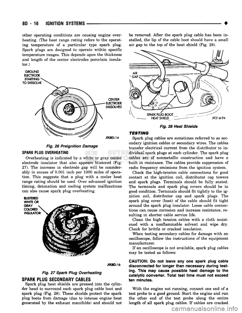
• other operating conditions are causing engine over
heating. (The heat range rating refers to the operat
ing temperature of a particular type spark plug.
Spark plugs are designed to operate within specific
temperature ranges. This depends upon the thickness and length of the center electrodes porcelain insula
tor.)
GROUND
ELECTRODE
CENTER
ELECTRODE
DISSOLVED
J908D-14 Fig. 26 Preignition Damage
SPARK
PLUG
OVERHEATING
Overheating is indicated by a white or gray center
electrode insulator that also appears blistered (Fig.
27).
The increase in electrode gap will be consider
ably in excess of 0.001 inch per 1000 miles of opera
tion. This suggests that a plug with a cooler heat
range rating should be used. Over advanced ignition
timing, detonation and cooling system malfunctions can also cause spark plug overheating.
BLISTERED
WHITE
OR
J908D-16
Fig. 27 Spark Plug Overheating
SPARK
PLUG
SECONDARY
CABLES
Spark plug heat shields are pressed into the cylin
der head to surround each spark plug cable boot and spark plug (Fig. 28). These shields protect the spark
plug boots from damage (due to intense engine heat
generated by the exhaust manifolds) and should not be removed. After the spark plug cable has been in
stalled, the lip of the cable boot should have a small
air gap to the top of the heat shield (Fig. 28).
Fig.
28 Heat
Shields
TESTING
Spark plug cables are sometimes referred to as sec
ondary ignition cables or secondary wires. The cables
transfer electrical current from the distributor to in dividual spark plugs at each cylinder. The spark plug
cables are of nonmetallic construction and have a
built in resistance. The cables provide suppression of radio frequency emissions from the ignition system.
Check the high-tension cable connections for good
contact at the ignition coil, distributor cap towers and spark plugs. Terminals should be fully seated.
The terminals and spark plug covers should be in good condition. Terminals should fit tightly to the ig
nition coil, distributor cap and spark plugs. The spark plug cover (boot) of the cable should fit tight
around the spark plug insulator. Loose cable connec
tions can cause corrosion and increase resistance, re sulting in shorter cable service life. Clean the high tension cables with a cloth moist
ened with a nonflammable solvent and wipe dry.
Check for brittle or cracked insulation. When testing secondary cables for damage with an
oscilloscope, follow the instructions of the equipment
manufacturer. If an oscilloscope is not available, spark plug cables
may be tested as follows:
CAUTION:
Do not leave any one
spark
plug
cable
disconnected
for
longer
than
necessary
during test
ing.
This
may
cause
possible
heat
damage
to the
catalytic converter. Total test
time
must
not exceed
ten
minutes.
With the engine not running, connect one end of a
test probe to a good ground. Start the engine and run the other end of the test probe along the entire length of all spark plug cables. If cables are cracked