1993 DODGE TRUCK fold seats
[x] Cancel search: fold seatsPage 612 of 1502

•
ENGINES
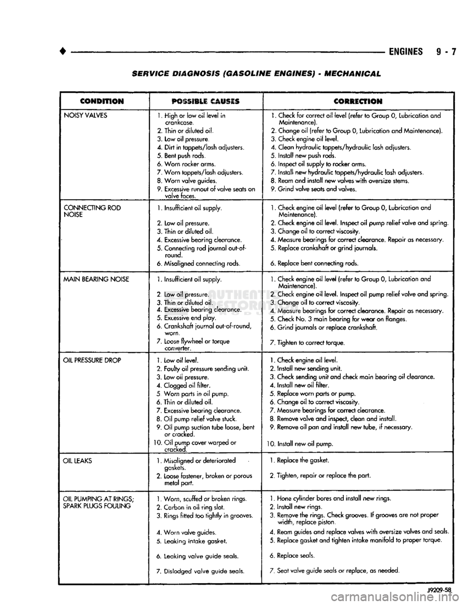
9 - 7 SERVICE DIAGNOSIS (GASOLINE ENGINES) - MECHANICAL
CONDITION
PSSSI1LI
CAUSIS
CORRECTION
NOISY
VALVES
1. High
or
low oil
level
in
crankcase.
2. Thin or
diluted
oil.
3.
Low
oil
pressure.
4.
Dirt
in
tappets/lash
adjusters.
5. Bent
push
rods.
6. Worn rocker arms.
7.
Worn
tappets/lash
adjusters.
8.
Worn
valve
guides.
9.
Excessive
runout
of
valve
seats
on
valve
faces.
1.
Check
for
correct oil
level
(refer
to
Group
0,
Lubrication and
Maintenance).
2. Change oil
(refer
to Group
0,
Lubrication and Maintenance).
3. Check engine oil level.
4. Clean hydraulic tappets/hydraulic lash adjusters.
5. Install new
push
rods.
6. Inspect oil supply to rocker arms.
7. Install new hydraulic tappets/hydraulic lash adjusters. 8. Ream and install new valves
with
oversize stems.
9. Grind valve seats and valves.
CONNECTING
ROD
NOISE
1.
Insufficient oil supply.
2.
Low oil
pressure.
3.
Thin
or
diluted
oil.
4.
Excessive
bearing
clearance.
5. Connecting rod
journal
out-of- round.
6. Misaligned connecting rods.
1.
Check engine oil
level
(refer
to Group
0,
Lubrication and
Maintenance).
2. Check engine oil level. Inspect oil pump
relief
valve and spring.
3. Change oil to correct
viscosity.
4. Measure bearings for correct clearance. Repair as necessary, 5. Replace crankshaft or grind journals.
6.
Replace
bent
connecting rods.
MAIN
BEARING
NOISE
1.
Insufficient oil supply.
2 Low
oil
pressure.
3. Thin or
diluted
oil.
4.
Excessive
bearing clearance. 5.
Excessive
end play.
6. Crankshaft
journal
out-of-round, worn,
7.
Loose
flywheel
or
torque
converter.
1.
Check engine oil
level
(refer
to Group
0,
Lubrication and
Maintenance).
2. Check engine oil level. Inspect oil pump
relief
valve and spring.
3. Change oil to correct
viscosity.
4. Measure bearings for correct clearance. Repair as necessary. 5. Check No.
3
main bearing for
wear
on flanges.
6. Grind journals
or
replace crankshaft.
7. Tighten to correct torque.
OIL
PRESSURE
DROP
1.
Low oil level.
2. Faulty oil pressure sending
unit.
3. Low
oil
pressure.
4.
Clogged
oil
filter.
5 Worn parts in
oil
pump.
6. Thin or
diluted
oil.
7.
Excessive
bearing clearance. 8.
Oil
pump
relief
valve stuck.
9. Oil pump suction
tube
loose,
bent
or cracked.
10.
Oil pump cover warped
or
cracked.
1.
Check engine oil level.
2. Install new sending
unit.
3. Check sending
unit
and check main bearing oil clearance.
4. Install new oil
filter.
5. Replace worn parts or pump. 6. Change oil to correct
viscosity.
7. Measure bearings for correct clearance.
8. Remove valve and inspect, clean and install. 9. Remove oil pan and install new tube,
if
necessary.
10. Install new oil pump.
OIL
LEAKS
1.
Misaligned or
deteriorated
gaskets.
2.
Loose
fastener, broken
or
porous
metal
part.
1. Replace the gasket.
2. Tighten,
repair
or replace the
part.
OIL
PUMPING
AT
RINGS;
SPARK
PLUGS
FOULING
1.
Worn, scuffed
or broken
rings.
2. Carbon in oil ring
slot.
3.
Rings
fitted
too
tightly
in grooves.
4. Worn valve guides.
5. Leaking
intake
gasket.
6. Leaking valve guide
seals.
7. Dislodged valve guide
seals.
1.
Hone cylinder bores and install new rings.
2. Install new rings.
3. Remove the rings. Check
grooves.
If
grooves
are not proper width, replace piston.
4. Ream guides and replace valves
with
oversize valves and
seals.
5. Replace gasket and tighten
intake
manifold
to
proper torque.
6. Replace
seals.
7. Seat
valve guide
seals
or
replace, as needed.
J9209-58
Page 1424 of 1502

•
BODY COMPONENTS
23 - 41
RELEASE
SCREW TRACK
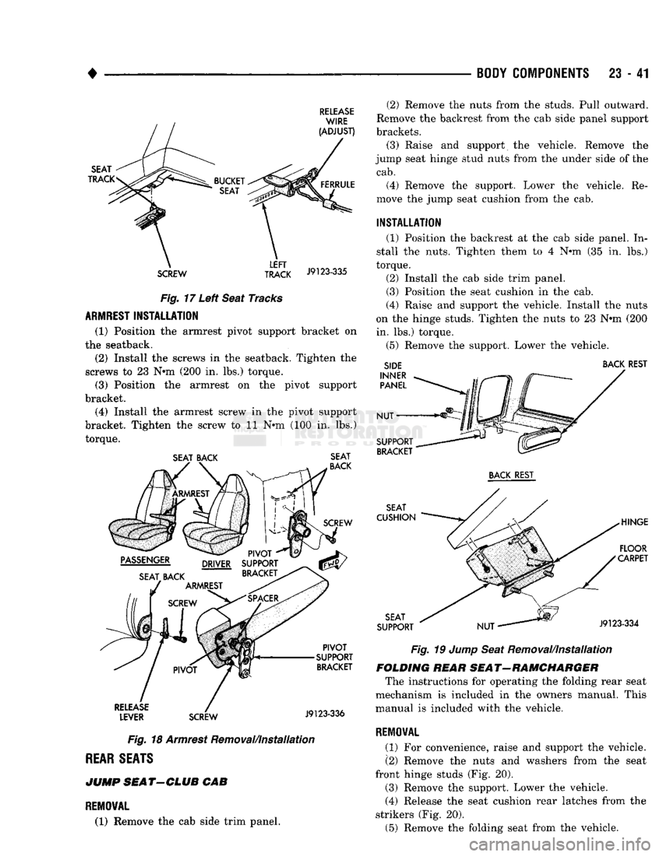
J9123"335 Fig. 17 Left Seat Tracks
ARMREST
INSTALLATION
(1) Position the armrest pivot support bracket on
the seatback.
(2) Install the screws in the seatback. Tighten the
screws to 23 N*m (200 in. lbs.) torque. (3) Position the armrest on the pivot support
bracket.
(4) Install the armrest screw in the pivot support
bracket. Tighten the screw to 11 N*m (100 in. lbs.) torque.
SEAT BACK SEAT
Fig. 18 Armrest Removal/Installation
REAR
SEATS
JUMP
SEAT-CLUB
CAB
REMOVAL
(1) Remove the cab side trim panel. (2) Remove the nuts from the studs. Pull outward.
Remove the backrest from the cab side panel support
brackets.
(3) Raise and support the vehicle. Remove the
jump seat hinge stud nuts from the under side of the
cab.
(4) Remove the support. Lower the vehicle. Re
move the jump seat cushion from the cab.
INSTALLATION
(1) Position the backrest at the cab side panel. In
stall the nuts. Tighten them to 4 N*m (35 in. lbs.)
torque.
(2) Install the cab side trim panel.
(3) Position the seat cushion in the cab.
(4) Raise and support the vehicle. Install the nuts
on the hinge studs. Tighten the nuts to 23 N#m (200 in. lbs.) torque.
(5) Remove the support. Lower the vehicle.
SIDE BACK REST
Fig. 19 Jump Seat Removal/installation
FOLDING HEAR SEAT-RAMCHARGER The instructions for operating the folding rear seat
mechanism is included in the owners manual. This
manual is included with the vehicle.
REMOVAL
(1) For convenience, raise and support the vehicle.
(2) Remove the nuts and washers from the seat
front hinge studs (Fig. 20).
(3) Remove the support. Lower the vehicle.
(4) Release the seat cushion rear latches from the
strikers (Fig. 20).
(5) Remove the folding seat from the vehicle.
Page 1429 of 1502

23
- 46
BODY
COMPONENTS
• (3) Bucket seats—detach the covers from the an
chor bolts for the left and right shoulder belt buckles.
(4) Remove the anchor bolts from the anchor plates
on the floor panel.
(5)
Remove the buckles and the lap belt from the
floor panel.
• Ram Trucks and Chassis Cabs—Remove the cover
concealing the shoulder belt upper anchor bolt.
• Ramchargers—Remove the quarter window trim
panel. If necessary, refer to the removal procedure.
(6) Remove the upper anchor bolt from the cab in
ner side panel/B-pillar.
• Ram Trucks and Chassis Cabs—Remove the shoul
der belt retractor and lower anchor bolt from the B-pillar.
• Ramchargers—Remove the screw and belt retrac
tor cover from the side inner panel. Remove the an chor bolts. Remove the retractor and lower belt from
the side inner panel.
(7) Remove the shoulder belts and retractors from
the vehicle.
INSTALLATION
(1) Position the shoulder belt retractor and the
lower end of the shoulder belt at the side inner
panel. Align the anchor bolt holes. Install the anchor
bolts.
Tighten the anchor bolts to 40 N*m (350 in. lbs.) torque.
• Ramchargers—Install the belt retractor cover and
the screw in the side inner panel. Tighten the screw
to 1 N»m (12 in. lbs.) torque.
(2) Position the shoulder belt upper anchor plate
on the trim panel. Install the upper anchor bolts in
the side panels. Tighten the anchor bolts to 40 N#m (350 in. lbs.) torque.
• Ram Trucks and Chassis Cabs—Install the cover
to conceal the shoulder belt upper anchor bolt.
• Ramchargers—Install the quarter window trim
panel. If necessary, refer to the installation proce
dure.
(3) Position the belt buckles on the floor panel.
(4) Install the shoulder belt buckles. Install the lap
belt and buckle anchor bolts in the floor panel.
Tighten the anchor bolts to 40 N«m (350 in. lbs.) torque.
• Bucket seats—Position the covers over the left and
right shoulder belt buckle anchor bolts.
(5) Connect the shoulder belt warning wire har
ness connectors. (6) If moved all the way forward for access, cor
rectly position the front seat.
REAR
SHOULDER
BELTS/LAP
BELT/BUCKLES-RAMCHARGER
REMOVAL
(1) If necessary, move the front seat(s) all the way
forward for access.
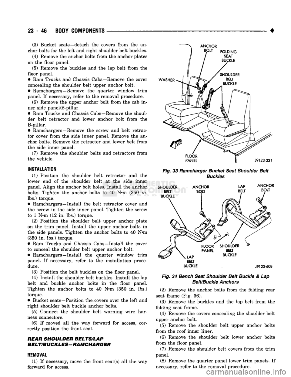
Fig.
33
Ramcharger
Bucket
Seat
Shoulder
Belt
Buckles
SHOULDER
ANCHOR
LAP
BELT
BUCKLE
.
J9123-608
Fig.
34
Bench
Seat
Shoulder
Belt
Buckle
& Lap
Belt/Buckle
Anchors
(2) Remove the anchor bolts from the folding rear
seat frame (Fig. 36). (3) Remove the buckles and the lap belt from the
folding seat frame. (4) Remove the covers concealing the shoulder belt
upper anchor bolt.
(5) Remove the shoulder belt upper anchor bolts
from the roof inner liner.
(6) Remove the shoulder belt lower anchor bolts
from the floor panel.
(7) Remove the shoulder belt covers from the trim
panel.
(8) Remove the quarter panel lower trim panels. If
necessary, refer to the removal procedure.