1993 DODGE TRUCK fuel additives
[x] Cancel search: fuel additivesPage 37 of 1502

0-18
LUBRICATION
AND
MAINTENANCE
• MAINTENANCE SCHEDULE
A crankcase ventilation system must be clean to
provide good operation and durability. Periodic main
tenance is necessary. Replace the PCV valve. Re
move residual combustion deposits from the hoses and throttle body/intake manifold passages.
The PCV valve should be replaced and the system
should be serviced at the interval specified in main
tenance schedule. If a vehicle is routinely used for short trips, the crankcase ventilation system could
possibly require more maintenance.
CRANKCASE AIR INLET FILTER
MAINTENANCE SCHEDULE Replace or clean, the air inlet filter at the interval
specified in maintenance schedule.
More frequent PCV system maintenance could be
required for:
• Vehicles routinely used for short trips
• Vehicles routinely involved in stop and go traffic
operation
• Vehicles routinely involved in extended periods of
engine idle
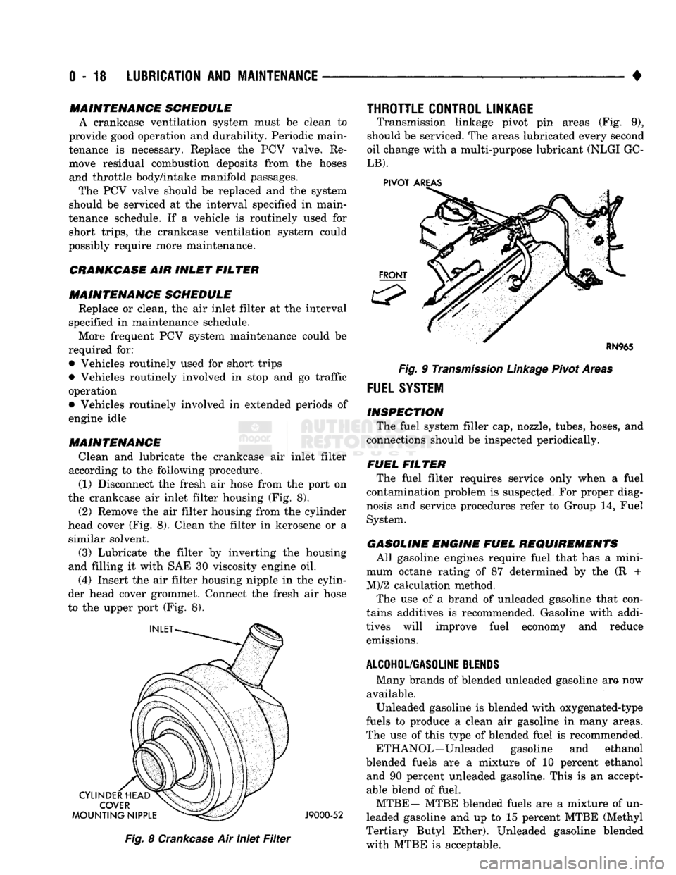
MAINTENANCE Clean and lubricate the crankcase air inlet filter
according to the following procedure. (1) Disconnect the fresh air hose from the port on
the crankcase air inlet filter housing (Fig. 8).
(2) Remove the air filter housing from the cylinder
head cover (Fig. 8). Clean the filter in kerosene or a similar solvent.
(3) Lubricate the filter by inverting the housing
and filling it with SAE 30 viscosity engine oil.
(4) Insert the air filter housing nipple in the cylin
der head cover grommet. Connect the fresh air hose
to the upper port (Fig. 8).
J9000-52
Fig.
8
Crankcase
Air Inlet
Filter
THROTTLE CONTROL LINKAGE
Transmission linkage pivot pin areas (Fig. 9),
should be serviced. The areas lubricated every second
oil change with a multi-purpose lubricant (NLGI GC-
LB).
PIVOT
AREAS
Fig.
9
Transmission
Linkage
Pivot Areas
FUEL
SYSTEM
INSPECTION The fuel system filler cap, nozzle, tubes, hoses, and
connections should be inspected periodically.
FUEL FILTER The fuel filter requires service only when a fuel
contamination problem is suspected. For proper diag
nosis and service procedures refer to Group 14, Fuel
System.
GASOLINE ENGINE FUEL REQUIREMENTS All gasoline engines require fuel that has a mini
mum octane rating of 87 determined by the (R +
M)/2 calculation method.
The use of a brand of unleaded gasoline that con
tains additives is recommended. Gasoline with addi
tives will improve fuel economy and reduce emissions.
ALCOHOL/GASOLINE
BLENDS
Many brands of blended unleaded gasoline am now
available. Unleaded gasoline is blended with oxygenated-type
fuels to produce a clean air gasoline in many areas.
The use of this type of blended fuel is recommended.
ETH ANOL—Unleaded gasoline and ethanol
blended fuels are a mixture of 10 percent ethanol and 90 percent unleaded gasoline. This is an accept
able blend of fuel.
MTBE— MTBE blended fuels are a mixture of un
leaded gasoline and up to 15 percent MTBE (Methyl
Tertiary Butyl Ether). Unleaded gasoline blended
with MTBE is acceptable.
Page 38 of 1502

•
LUBRICATION
AND
MAINTENANCE
0 - 19 ETBE— This fuel is a mixture of unleaded gasoline
and up to 17 percent ETBE (Ethyl Tertiary Butyl
Ether).
Unleaded gasoline blended with ETBE is ac ceptable.
METHANOL—Do not use unleaded gasoline
blended with methanol. The use of this type of alco hol can result in engine performance and damage to
critical components. Engine problems that result
from the use of methanol possibly will not be covered by the new vehicle warranty.
Certain brands of unleaded gasoline contain a per
centage of unidentified alcohol. These types of un
leaded gasoline are not recommended.
ADDITIVES MIXED
WITH
GASOLINE
Use of fuel system cleaning additives should be
avoided. Many of these solutions could contain highly
active solvents. This type of solvent can be harmful
to the gasket and diaphragm material within the fuel system.
DIESEL
ENGINE FUEL REQUIREMENTS
All Diesel engines normally can use number 2D
Diesel fuel for most year-round operations. A fuel
conforming to ASTM Specification D-975 is recom
mended. For extreme cold-weather operation (below
-18°C/0°F), or for prolonged cold-climate operation ei
ther:
• Use No. ID fuel, or
• Add an equal quantity of kerosene to No. 2D fuel (a 50/50 mixture).
Both methods provide protection against fuel gel
ling and waxing.
Diesel fuel seldom is without water contamination.
To help prevent fuel system malfunctions, drain all accumulated water from the separators periodically.
VACUUM OPERATED,
EMISSION
CONTROL
COMPONENTS
MAINTENANCE SCHEDULE
The following emission controls should be replaced
at the interval specified in the maintenance sched
ule:
• Bi-level purge check valves
• Delay valves
• Heated air temperature sensor (HATS)
• Air cleaner vacuum motors
EXHAUST
GAS RECIRCULATION (EGR)
SYSTEM
MAINTENANCE SCHEDULE
Replace the EGR valve and tube, and clean the
passages at the interval specified in maintenance schedule. If necessary, refer to Group 25—Emission
Control Systems for additional information.
OXYGEN
(02)
SENSOR
MAINTENANCE SCHEDULE
Replace the 02 sensor at the interval specified in
maintenance schedule.
IGNITION
CABLES,
DISTRIBUTOR CAP AND
ROTOR
MAINTENANCE SCHEDULE
Replace the ignition cables, distributor cap, and ro
tor at the interval specified in maintenance schedule.
Inspect the distributor for excessive wear and re
place, as necessary. Refer to Group 8D—Ignition Sys
tems for additional information.
IGNITION TIMING
MAINTENANCE SCHEDULE
Test and adjust, if necessary, the ignition timing at
the interval specified in maintenance schedule. Refer
to the specifications listed on the engine Emission Control Information label. Refer to Group 8D—Igni
tion Systems and to Group 25—Emission Control Systems for additional service information.
SPARK
PLUGS MAINTENANCE SCHEDULE
Replace the spark plugs at the interval specified in
maintenance schedule. Refer to the Spark Plugs
chart below and to Group 8D—Ignition Systems for additional service information.
SPARK
PLUGS
ENGINE
SPARK
PLUG
SPARK
PLUG
GAP
TORQUE
3.9L
5.2L
5.9L
RN12YC
RN12YC
RN12YC
0.9 mm
(0.035
in.)
0.9 mm
(0.035
in.)
0.9 mm
(0.035
in.) 41 N*m (30 ft. lb.)
41 NVn (30 ft. lb.)
41 N*m (30 ft. lb.)
J9100-17
BATTERY
MAINTENANCE SCHEDULE
Replace battery at interval specified in mainte
nance schedule.
Page 366 of 1502

•
IGNITION
SYSTEMS
8D - 15 J908D-15
Fig.
22 Normal Operation and Cold (Carbon) Fouling
sically carbon (Fig. 22). A dry, black deposit on one
or two plugs in a set may be caused by sticking
valves or defective spark plug cables. Cold (carbon)
fouling of the entire set of spark plugs may be caused
by a clogged air filter or .repeated short operating
times (short trips).
ELECTRODE GAP BRIDGIMG
Electrode gap bridging may be traced to loose de
posits in the combustion chamber. These deposits ac cumulate on the spark plugs during continuous stop-
and-go driving. When the engine is suddenly
subjected to a high torque load, deposits partially liq
uefy and bridge the gap between electrodes (Fig. 28).
This short circuits the electrodes. Spark plugs with electrode gap bridging can be cleaned using standard
procedures.
GROUND
ELECTRODE
J908D-11
Fig. 23 Electrode Gap Bridging
SCAVENGER
DEPOSITS
Fuel scavenger deposits may be either white or yel
low (Fig. 24). They may appear to be harmful, but
this is a normal condition caused by chemical addi
tives in certain fuels. These additives are designed to change the chemical nature of deposits and decrease
spark plug misfire tendencies. Notice that accumula
tion on the ground electrode and shell area may be
heavy, but the deposits are easily removed. Spark
plugs with scavenger deposits can be considered nor mal in condition and can be cleaned using standard
procedures.
GROUND
ELECTRODE
COVERED
J908D-12
Fig.
24
Scavenger
Deposits
CHIPPED ELECTRODE
INSULATOR
A chipped electrode insulator usually results from
bending the center electrode while adjusting the spark plug electrode gap. Under certain conditions, severe detonation can also separate the insulator
from the center electrode (Fig. 25). Spark plugs with
this condition must be replaced.
GROUND
J908D-13
Fig.
25
Chipped
Electrode Insulator
PREIGNITION
DAMAGE
Preignition damage is usually caused by excessive
combustion chamber temperature. The center elec
trode dissolves first and the ground electrode dis solves somewhat latter (Fig. 26). Insulators appear
relatively deposit free. Determine if the spark plug
has the correct heat range rating for the engine. De
termine if ignition timing is over advanced, or if
Page 820 of 1502

•
FUEL
SYSTEM
14 - 1
FUEL
SYSTEM
page
ACCELERATOR
PEDAL
AND THROTTLE
CABLE
................ 25
DIESEL
FUEL
INJECTION-COMPONENT
DESCRIPTION/SYSTEM
OPERATION
76
DIESEL
FUEL
INJECTION-GENERAL
DIAGNOSIS
88
DIESEL
FUEL
INJECTION-SERVICE
PROCEDURES
....................... 106
FUEL
DELIVERY
SYSTEM-EXCEPT
DIESEL
.. 3
FUEL
DELIVERY-DIESEL
ENGINE
15
FUEL
TANKS
.... 20
page
GENERAL
INFORMATION 1
MULTI-PORT
FUEL
INJECTION (MPI)-
COMPONENT
DESCRIPTION/SYSTEM
OPERATION-EXCEPT
DIESEL
29
MULTI-PORT
FUEL
INJECTION (MPI)-
COMPONENT
REMOVAL/INSTALLATION-
EXCEPT
DIESEL
64
MULTI-PORT
FUEL
INJECTION (MPI)-
GENERAL
DIAGNOSIS-EXCEPT
DIESEL
...43
SERVICE
ADJUSTMENTS-DIESEL
122
SPECIFICATIONS
123
GENERAL INFORMATION
Throughout this group, references are made to par
ticular vehicle models by alphabetical designation or
by the particular vehicle nameplate. A chart showing a breakdown of the alphabetical designations is in
cluded in the Introduction section at the beginning of
this manual.
The 5.9L (V-8) gas powered engine will be referred
to in this group as either the: LDC (Light Duty Cy cle) or HDC (Heavy Duty Cycle) engine. The HDC engine can be easily identified by the use of an en
gine mounted air injection pump. The 3.9L/5.2L/5.9L
LDC engine will not use an air injection pump.
This Fuel System group will cover all fuel system
components for the 3.9L (V-6), 5.2L (V-8), 5.9L LDC
(V-8),
5.9L HDC (V-8) and 5.9L (in-line six cylinder)
diesel engines.
The Fuel System consists of: the fuel tank, an
electric (fuel tank mounted) fuel pump and fuel fil
ter. It also consists of fuel tubes/lines/hoses, vacuum
hoses,
throttle body and fuel injector(s).
The Fuel Delivery System consists of: the electric
fuel pump, fuel filter, fuel tubes/lines/hoses, fuel rail,
fuel injectors and fuel pressure regulator.
A Fuel Return System is used on all vehicles (all
engines) except the 5.9L (V-8) gas powered engine. On this engine, a returnless type fuel system is
used. The fuel return system consists of fuel tubes/
lines and hoses that route fuel back to the fuel tank.
The Fuel Tank Assembly consists of: the fuel
tank, filler tube, fuel gauge sending unit/electric fuel
pump module, a pressure relief/rollover valve and a
pressure-vacuum filler cap. Also to be considered part of the fuel system is the
Evaporation Control System. This is designed to
reduce the emission of fuel vapors into the atmo sphere. The description and function of the Evapora
tive Control System is found in Group 25, Emission Control Systems.
FUEL
USAGE
STATEMENT-GAS
ENGINES
Your vehicle was designed to meet all emission
regulations and provide excellent fuel economy using
high quality unleaded gasoline. Only use unleaded gasolines having a minimum posted octane of 87. If your vehicle develops occasional light spark
knock (ping) at low engine speeds, this is not harm
ful.
However, continued heavy knock at high speeds can cause damage and should be re
ported to your dealer immediately. Engine dam age as a result of heavy knock operation may not be
covered by the new vehicle warranty. In addition to using unleaded gasoline with the
proper octane rating, those that contain deter
gents,
corrosion and stability additives are rec
ommended. Using gasolines that have these additives will help improve fuel economy, reduce
emissions and maintain vehicle performance. Gener ally, premium unleaded gasolines contain more addi
tive than regular unleaded gasolines. Poor quality gasoline can cause problems such as
hard starting, stalling and stumble. If you experience
these problems, use another brand of gasoline before considering service for the vehicle.