1993 DODGE TRUCK instrument panel
[x] Cancel search: instrument panelPage 6 of 1502
INTRODUCTION
INTRODUCTION
DESIGNATIONS,
LABELS/PLATES/DECALS,
CODES
AND DIMENSIONS/WEIGHTS .
CONTENTS
page
MEASUREMENT
AND TORQUE
... 1 SPECIFICATIONS
page
. 11
DESIGNATIONS, LABELS/PLATES/DECALS, CODES
AND
DIMENSIONS/WEIGHTS
INDEX
page
Engine
and
Transmission/Transfer
Case
Identification
2
Engine/Transmission/GVWR
4
Equipment
Identification
Plate
3
International
Vehicle Control
and
Display
Symbols
10
Major Component
Identification 3
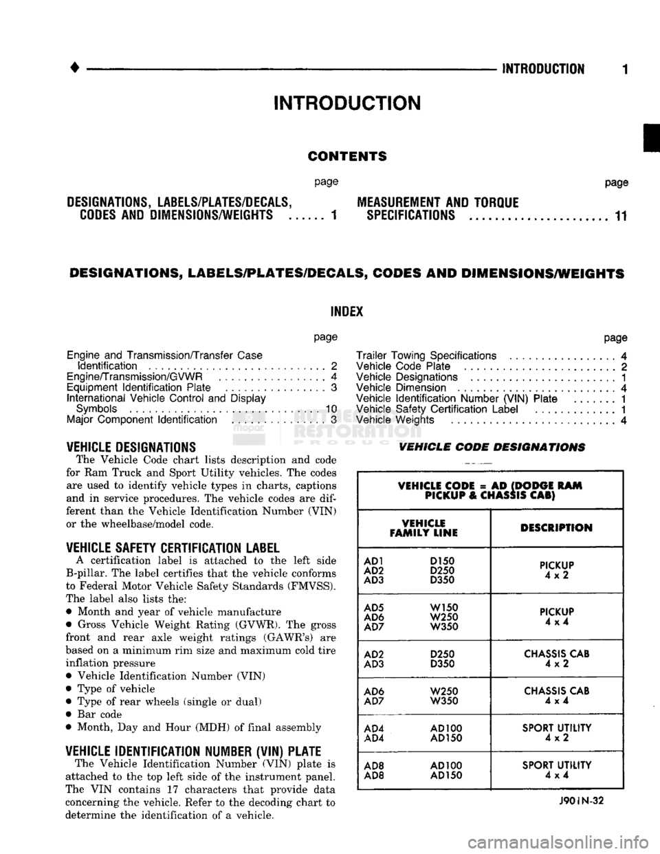
VEHICLE DESIGNATIONS The Vehicle Code chart lists description and code
for Ram Truck and Sport Utility vehicles. The codes are used to identify vehicle types in charts, captions
and in service procedures. The vehicle codes are
dif
ferent than the Vehicle Identification Number (VIN) or the wheelbase/model code.
VEHICLE SAFETY CERTIFICATION
LABEL
A certification label is attached to the left side
B-pillar. The label certifies that the vehicle conforms
to Federal Motor Vehicle Safety Standards (FMVSS).
The label also lists the: • Month and year of vehicle manufacture
• Gross Vehicle Weight Rating (GVWR). The gross
front and rear axle weight ratings (GAWR's) are
based on a minimum rim size and maximum cold tire inflation pressure Vehicle Identification Number (VIN)
Type of vehicle
Type of rear wheels (single or dual) Bar code
Month, Day and Hour (MDH) of final assembly
VEHICLE IDENTIFICATION NUMBER (VIN) PLATE The Vehicle Identification Number (VIN) plate is
attached to the top left side of the instrument panel.
The VIN contains 17 characters that provide data
concerning the vehicle. Refer to the decoding chart to
determine the identification of a vehicle.
page
Trailer
Towing Specifications
4
Vehicle Code Plate
2
Vehicle Designations
1
Vehicle Dimension
4
Vehicle
Identification
Number (VIN) Plate
1
Vehicle Safety
Certification
Label
............. 1
Vehicle Weights
4
VEHICLE CODE
DESIGNATIONS
VEHICLE CODE
= AD
(DODGE
RAM
PICKUP
&
CHASSIS
CAB)
VEHICLE
FAMILY LINE DESCRIPTION
AD1
D150
AD2
D250
AD3
D350
PICKUP
4x2
AD5
W150
AD6
W250
AD7
W350
PICKUP
4x4
AD2
D250
AD3
D350
CHASSIS
CAB
4x2
AD6
W250
AD7
W350
CHASSIS
CAB
4x4
AD4
AD100
AD4
AD150
SPORT
UTILITY
4x2
AD8
AD100
AD8 AD
150
SPORT
UTILITY
4x4
J90IN-32
Page 15 of 1502
10 INTRODUCTION
•
INTERNATIONAL CONTROL AND DISPLAY SYMBOLS
ID
HIGH
BEAM P
FOG UGHTS -&
HEADLIGHTS,
PARKING UGHTS, PANEL UGHTS TURN SIGNAL A
HAZARD WARNING WINDSHIELD
WASHER
WINDSHIELD WIPER WINDSHIELD WIPER
AND WASHER
AND DEFROSTING *
VENTILATING
FAN 8
M f
REAR
WINDOW DEFOGGER
sp
REARWINLX)W WIPER
CD
l
m
REAR
WINDOW WASHER FUEL ENGINE COOLANT
TEMPERATURE BATTERY CHARGING
CONDITION ENGINE OIL
SEAT
BELT
(©) (®) ky
11 J
LIGHTER
BRAKE
FAILURE
PARKING
BRAKE
FRONT HOOD
REAR
HOOD
(TRUNK)
HORN
11 J
LIGHTER
93IN-9
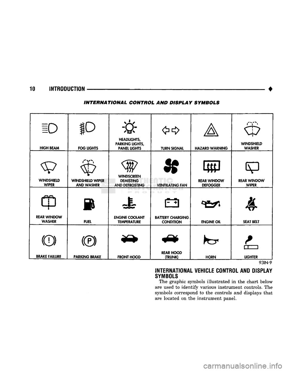
INTERNATIONAL VEHICLE CONTROL AND DISPLAY
SYMBOLS
The graphic symbols illustrated in the chart below
are used to identify various instrument controls. The
symbols correspond to the controls and displays that are located on the instrument panel.
Page 22 of 1502

•
LUBRICATION AND MAINTENANCE
0 - 3
CAUTION: UNLEADED FUEL ONLY must
be
used
in
vehicles equipped
with
a
catalyst emission
control
system.
All
vehicles have reminders
printed
on the
instrument
panel below
the
fuel
gauge
and on the
fuel
filler
door.
The
vehicles also have
fuel
filler
tubes
that
are
specially designed
to
accept only
the
small-diameter nozzles.
It is
illegal
to
bypass
the
design
of an
unleaded
fuel
filler
tube.
DIESEL ENGINES All
Ram
Truck
and Ram
Cab/Chassis Diesel
en
gines normally
can use
number
2D
Diesel fuel
for
most year-round operations.
A
fuel conforming
to
ASTM Specification D-975
is
recommended.
For ex
treme cold-weather, number
ID
Diesel fuel
is
recom mended.
CLASSIFICATION
OF
LUBRICANTS
Lubricating fluids
and
chassis lubricants
are
clas
sified according
to
standards recommended
by the:
• Society
of
Automotive Engineers
(SAE)
• American Petroleum Institute
(API)
• National Lubricating Grease Institute (NLGI)
ENGINE
OIL
SAE
VISCOSITY
GRADE
An
SAE
viscosity grade
is
used
to
specify
the
vis
cosity
of
engine
oil. SAE 30
specifies
a
single viscos
ity engine
oil.
Engine oils also have multiple viscosities. These
are specified with
a
dual
SAE
viscosity grade which
indicates
the
cold-to-hot temperature viscosity range (Fig.
3).
API
SERVICE
GRADE
The
API
Service Grade specifies
the
type
of
perfor
mance
the
engine
oil is
intended
to
provide.
The API
Service Grade specifications also apply
to
energy con
serving engine oils
(Fig. 3).
For maximum gasoline engine protection,
use API
Service Grade
SG,
SG/CD
or
SG/CE engine
oil.
For maximum Diesel engine protection,
use
API Service
CE or
SG/CE engine
oil.
GEAR LUBRICANTS A dual grade
is
also used
to
specify
the
viscosity
of
multi-purpose gear lubricants.
The
API
grade designation identifies gear lubri
cants
in
terms
of
recommended usage.
OIL
QUALITY
SAE
VISCOSITY
GRADE
FUEL
ECONOMY
NOTATION
J91004
Fig.
3 SAE Oil
Viscosity Grade
& API
Service
Grade
CHASSIS COMPONENT
AND
WHEEL BEARING
LUBRICANTS The chassis
and
wheel bearing lubricants
are
iden
tified
by the
NLGI Certification Symbol.
The
symbol
contains
a
coded designation. This identifies
the us
age
and
quality
of the
lubricant.
The letter
G
within
the
symbol designates wheel
bearing lubricant.
The
letter
L
designates chassis
lu
bricant. When
the
letters
are
combined,
the
lubricant can
be
used
for
dual applications.
Use
only lubricants
that display
the
NLGI Certification Symbol.
NATIONAL LUBRICATING
GREASE
INSTITUTE
NLGI
AUTOMOTIVE
WHEEL BEARING
&
CHASSIS LUBRICANT
GC-LB
-CERTIFICATION
SYMBOL
—
USAGE
AND
QUALITY
DESIGNATION
J920W7
Fig.
4
NLGI
Lubricant Container
Certification/
Identification
Symbol
LUBRICATION
AND
REPLACEMENT
PARTS
RECOMMENDATION
Ram Trucks
are
engineered
to
provide many years
of dependable operation. However, lubrication service
and maintenance
are
required
for
each vehicle. When
necessary, MOPAR®brand lubricants
and
genuine
re
placement parts
are
recommended.
Page 52 of 1502
•
LUBRICATION
AND
MAINTENANCE
0 - 33 BODY LUBRICANT SPECIFICATIONS
COMPONENT
SERVICE
INTERVAL
LUBRICANT
Door
Hinges
As
Required
Engine
Oil
Door
Latches
As
Required Multi-Purpose Grease
NLGI
GC-LB
(Water
Resistant)
(1)
Hood
Latch Release Mechanism
&
Safety Latch
As
Required
(When Performing Other Underhood Services) Multi-Purpose Grease
NLGI
GC-LB
2
EP
(2)
Hood
Hinges
As
Required
Engine
Oil
Seat Regulator
&
Track Release Mechanism
As
Required Multi-Purpose Grease
NLGI
GC-LB
2
EP
(2)
Tailgate Hinge
As
Required Multi-Purpose Grease
NLGI
GC-LB
2
EP
(2)
Tailgate Support Arms
As
Required
Engine
Oil
Tailgate Latches
As
Required
White
Spray Lubricant
(3)
Tailgate Release Handle (Pivot & Slide Contact Surfaces)
As
Required Multi-Purpose Grease
NLGI
GC-LB
2
EP
(2)
Window System Components (Regulators, Tracks,
Rods
&
Channel Areas — Except
Glass
Run Weatherstrips
and
Felt
Lubricator,
if
Equipped)
As
Required
White
Spray Lubricant
(3)
Lock
Cylinders Twice/Year
Lock
Cylinder Lubricant
(4)
Parking Brake Mechanism
As
Required Multi-Purpose Grease
NLGI
GC-LB
(1)
1.
Mopar
Wheel
Bearing Grease (High
Temperature)
2. Mopar Multi-Mileage Lubricant 3. Mopar Spray
White
Lube
4. Mopar Lock Cylinder Lubricant
J9200-58
SPEEDOMETER
CABLE
SERVICE INFORMATION Speedometer cable lubrication is not necessary. For
service information involving noisy or erratic cables,
refer to Group 8E—Instrument Panel and Gauges.
Page 247 of 1502
5
- 60
BRAKES
Fig.
2
Antilock
Electronic Control
Module
RWAL
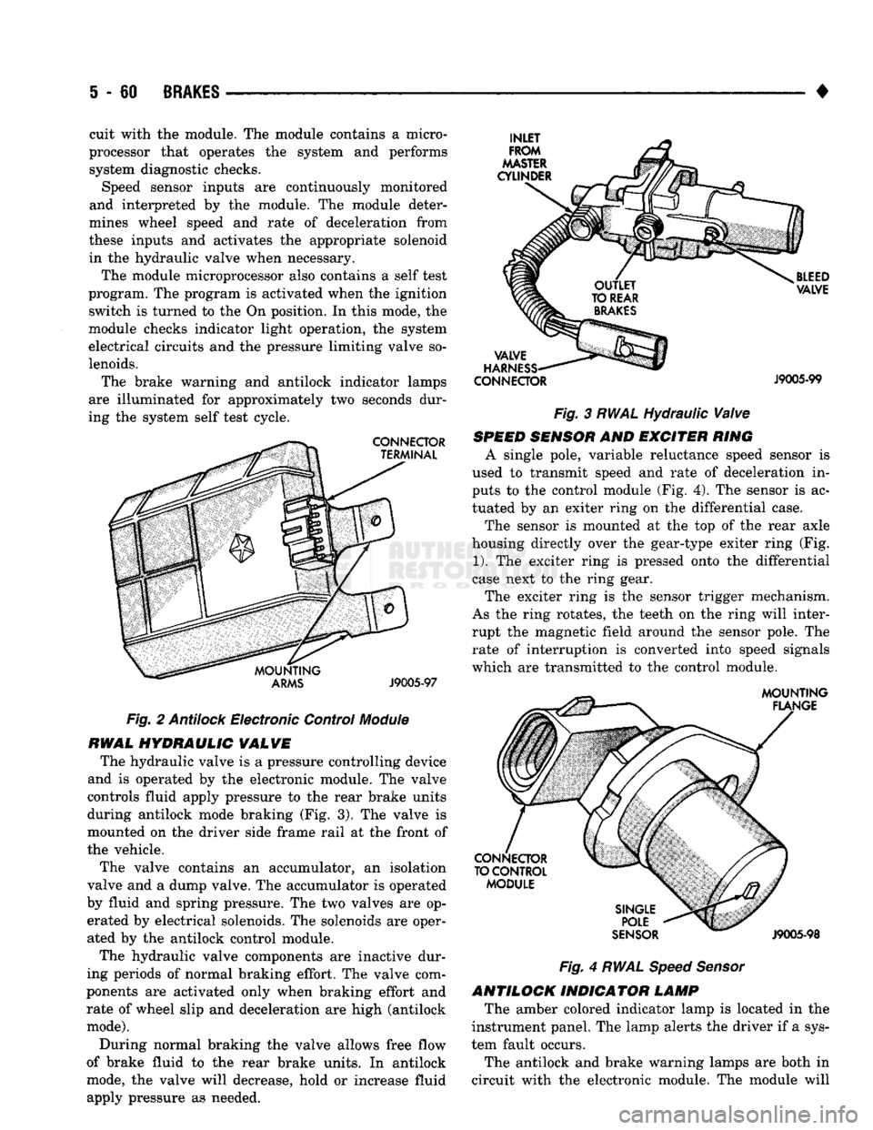
HYDRAULIC
VALVE
The hydraulic valve is a pressure controlling device
and is operated by the electronic module. The valve
controls fluid apply pressure to the rear brake units
during antilock mode braking (Fig. 3). The valve is
mounted on the driver side frame rail at the front of
the vehicle.
The valve contains an accumulator, an isolation
valve and a dump valve. The accumulator is operated
by fluid and spring pressure. The two valves are op erated by electrical solenoids. The solenoids are oper
ated by the antilock control module.
The hydraulic valve components are inactive dur
ing periods of normal braking effort. The valve com
ponents are activated only when braking effort and rate of wheel slip and deceleration are high (antilock
mode).
During normal braking the valve allows free flow
of brake fluid to the rear brake units. In antilock
mode, the valve will decrease, hold or increase fluid
apply pressure as needed. •
CONNECTOR
J9005-99
Fig. 3 RWAL Hydraulic Valve
SPEED
SENSOR
AND EXCITER RING
A single pole, variable reluctance speed sensor is
used to transmit speed and rate of deceleration in
puts to the control module (Fig. 4). The sensor is ac
tuated by an exiter ring on the differential case.
The sensor is mounted at the top of the rear axle
housing directly over the gear-type exiter ring (Fig.
1).
The exciter ring is pressed onto the differential
case next to the ring gear.
The exciter ring is the sensor trigger mechanism.
As the ring rotates, the teeth on the ring will inter
rupt the magnetic field around the sensor pole. The rate of interruption is converted into speed signals
which are transmitted to the control module.
Fig.
4
RWAL Speed Sensor
ANTILOCK INDICATOR LAMP The amber colored indicator lamp is located in the
instrument panel. The lamp alerts the driver if a sys
tem fault occurs.
The antilock and brake warning lamps are both in
circuit with the electronic module. The module will
cuit with the module. The module contains a micro
processor that operates the system and performs system diagnostic checks. Speed sensor inputs are continuously monitored
and interpreted by the module. The module deter
mines wheel speed and rate of deceleration from
these inputs and activates the appropriate solenoid in the hydraulic valve when necessary.
The module microprocessor also contains a self test
program. The program is activated when the ignition switch is turned to the On position. In this mode, the
module checks indicator light operation, the system
electrical circuits and the pressure limiting valve so
lenoids.
The brake warning and antilock indicator lamps
are illuminated for approximately two seconds dur
ing the system self test cycle.
Page 294 of 1502
•
COOLING SYSTEM
7 - 23
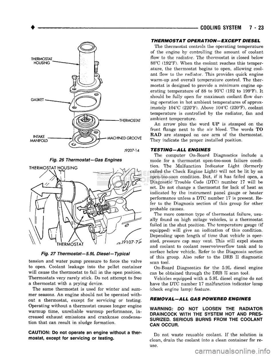
•THERMOSTAT
MACHINED GROOVE
J9207-14
Fig.
26
Thermostat—
Gas Engines
Fig.
27 Thermostat—5.9L Diesel—Typical
tension and water pump pressure to force the valve
to open. Coolant leakage into the pellet container
will cause the thermostat to fail in the open position.
Thermostats very rarely stick. Do not attempt to free a thermostat with a prying device.
The same thermostat is used for winter and sum
mer seasons. An engine should not be operated with
out a thermostat, except for servicing or testing. Operating without a thermostat causes longer engine
warmup time, unreliable warmup performance, in
creased exhaust emissions and crankcase condensa
tion that can result in sludge formation.
CAUTION:
Do not operate an engine without a
ther
mostat,
except for
servicing
or
testing.
THERMOSTAT OPERATION-EXCEPT DIESEL
The thermostat controls the operating temperature
of the engine by controlling the amount of coolant
flow to the radiator. The thermostat is closed below 88°C (192°F). When the coolant reaches this temper
ature, the thermostat begins to open, allowing cool
ant flow to the radiator. This provides quick engine
warm-up and overall temperature control. The ther
mostat is designed to provide a minimum engine op erating temperature of 88 to 93°C (192 to 199°F). It
should be fully open for maximum coolant flow dur
ing operation in hot ambient temperatures of approx
imately 104°C (220°F). Above 104°C (220°F), coolant
temperature is controlled by the radiator, fan and ambient temperature.
An arrow plus the word UP is stamped on the
front flange next to the air bleed. The words TO RAD are stamped on one arm of the thermostat.
They indicate the proper installed position.
TESTING-ALL ENGINES The computer On-Board Diagnostics include a
mode for a thermostat open-too-soon failure condi
tion. The Malfunction Indicator Light (formerly called the Check Engine Light) will not be lit by an
open-too-soon condition. But, if it has failed open, a
Diagnostic Trouble Code (DTC) number 17 will be
set. Do not change a thermostat for lack of heat as
indicated by the instrument panel gauge or heater
performance unless a DTC number 17 is present. Re
fer to the Diagnosis section of this group for other
probable causes.
The more common type of thermostat failure, usu
ally found on high milage vehicles, is a thermostat
failed in the shut position. The temperature gauge (if equipped) will give an indication of this condition.
Depending upon length of time that vehicle is oper
ated, pressure cap may vent. This will expel steam
and coolant to coolant reserve/overflow tank and to
surface below vehicle. Refer to the Diagnosis section
of this group. Also refer to the DRB II diagnostic
scan tool.
On-Board Diagnostics for the 5.9L diesel engine
can be obtained through the DRB II scan tool.
Vehicles equipped with a 5.9L diesel engine do not
have the DTC number 17 malfunction indicator lamp (check engine lamp) feature.
REMOVAL-ALL GAS POWERED ENGINES
WARNING:
DO NOT
LOOSEN
THE
RADIATOR DRAINCOCK
WITH
THE
SYSTEM
HOT AND
PRES
SURIZED.
SERIOUS BURNS FROM
THE
COOLANT
CAN
OCCUR.
Do not waste reusable coolant. If the solution is
clean, drain the coolant into a clean container for re
use.
Page 322 of 1502
•
ELECTRICAL
ELECTRICAL
8A - 1
Group
AUDIO
SYSTEMS
8F
BATTERY/STARTER/GENERATOR
SERVICE
.. 8B
BATTERY/STARTING/CHARGING
SYSTEMS
DIAGNOSTICS
8A
HORNS
8G
IGNITION
SYSTEMS
8D
INSTRUMENT PANEL AND
GAUGES
8E
LAMPS
8L
POWER
LOCKS
8P
INDEX
Group
POWER
MIRRORS
8T
POWER
WINDOWS 8S
REAR
WINDOW DEFOGGER 8N
TURN
SIGNALS
AND HAZARD WARNING
FLASHERS
8J
VEHICLE
SPEED
CONTROL SYSTEM 8H WARNING BUZZER SYSTEM 8U
WINDSHIELD WIPERS AND
WASHERS
8K
WIRING DIAGRAMS 8W
BATTERY/STARTING/CHARGING SYSTEMS DIAGNOSTICS
CONTENTS
page
page
BATTERY TEST
PROCEDURES
2 GENERATOR TEST
PROCEDURES
ON VEHICLE . 13
ENGINE
STARTER MOTOR TEST
PROCEDURES
..9 SPECIFICATIONS 18
GENERAL
INFORMATION 1
GENERAL INFORMATION
The Battery, Starting, and Charging Systems oper
ate with one another, and therefore, must be thor
oughly tested as a complete system. In order for the
vehicle to start and charge properly, it must have a
battery that will perform to specifications. The starter
motor, generator, wiring, and electronics also must
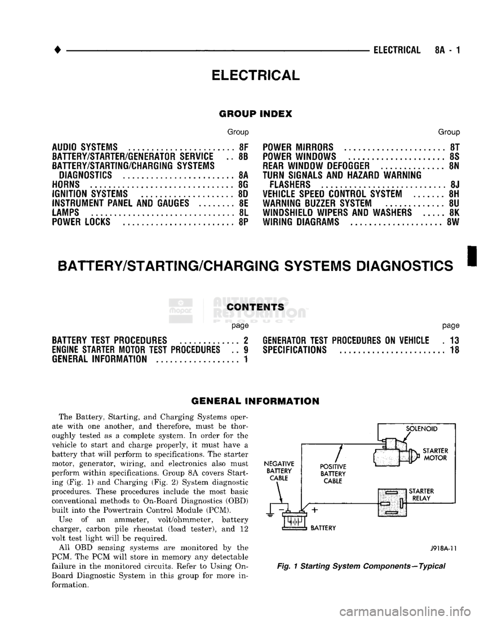
perform within specifications. Group 8A covers Start ing (Fig. 1) and Charging (Fig. 2) System diagnostic
procedures. These procedures include the most basic
conventional methods to On-Board Diagnostics (OBD)
built into the Powertrain Control Module (PCM).
Use of an ammeter, volt/ohmmeter, battery
charger, carbon pile rheostat (load tester), and 12
volt test light will be required.
All OBD sensing systems are monitored by the
PCM. The PCM will store in memory any detectable
failure in the monitored circuits. Refer to Using On-
Board Diagnostic System in this group for more in formation.
NEGATIVE
BATTERY
CABLE
A
7
POSITIVE
BATTERY
CABLE
BATTERY
J918A-11
Fig.
1 Starting
System
Components—Typical
Page 382 of 1502
• • ^ ^ ^ INSTRUMENT PANEL AND GAUGES 8E - 1
CONTENTS
page
CLUSTER AND GAUGE SERVICE PROCEDURES . 12
CLUSTER AND GAUGE TEST PROCEDURES .. i
GENERAL INFORMATION . 1
page
MESSAGE CENTER-DIESEL ENGINE ........ 4
MESSAGE CENTER-GAS ENGINE .......... 3
SWITCH
AND PANEL COMPONENT SERVICE . 16
GENERAL
INFORMATION
INDEX
page
Generator
Indicating
System
2
Distance
Sensor
2
Electronic
Digital
Clock
3
Fuel
Level
Indicating
System
1
page
Malfunction
Indicator
(Check
Engine)
3
Oil
Pressure
Warning
Lamp
................. 2
Speedometer/Odometer
System
2
Temperature
and Oil
Indicating
System
......... 2
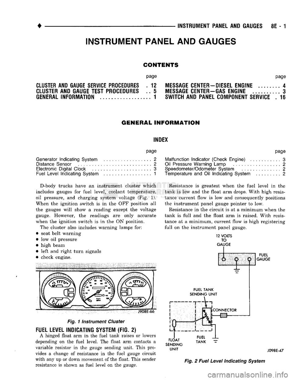
D-body trucks have an instrument cluster which
includes gauges for fuel level, coolant temperature,
oil pressure, and charging system voltage (Fig. 1).
When the ignition switch is in the OFF position all
the gauges will show a reading except the voltage gauge. However, the readings are only accurate
when the ignition switch is in the ON position.
The cluster also includes warning lamps for:
• seat belt warning
• low oil pressure
• high beam
• left and right turn signals
• check engine. J908E-66
Fig.
11nstrument
Cluster
FUEL LEVEL INDICATING SYSTEM (FIG. 2)
A hinged float arm in the fuel tank raises or lowers
depending on the fuel level. The float arm contacts a
variable resistor in the gauge sending unit. This pro
vides a change of resistance in the fuel gauge circuit
with any up or down movement of the float. This sender
resistance is shown as fuel level on the gauge. Resistance is greatest when the fuel level in the
tank is low and the float arm drops. With high resis
tance current flow is low and consequently positions
the instrument panel gauge pointer to low.
Resistance in the circuit is at a minimum when the
tank is full and the float arm is raised. With resis
tance at a minimum, current flow is high registering
full on the instrument panel gauge.
12
VOLTS
TO
GAUGE
IP
FUEL
TANK
SENDING
UNIT
FLOAT
SENDING
UNIT
1:
1
j
^
fCONNECTOR
!g|yj-»—
FUEL
GAUGE
FUEL
TANK
J098E-47
Fig.
2
Fuel
Level
Indicating
System
INSTRUMENT PANEL AND GAUGES