1993 DODGE TRUCK hood release
[x] Cancel search: hood releasePage 51 of 1502
0
- 32
LUBRICATION
AND
MAINTENANCE
•
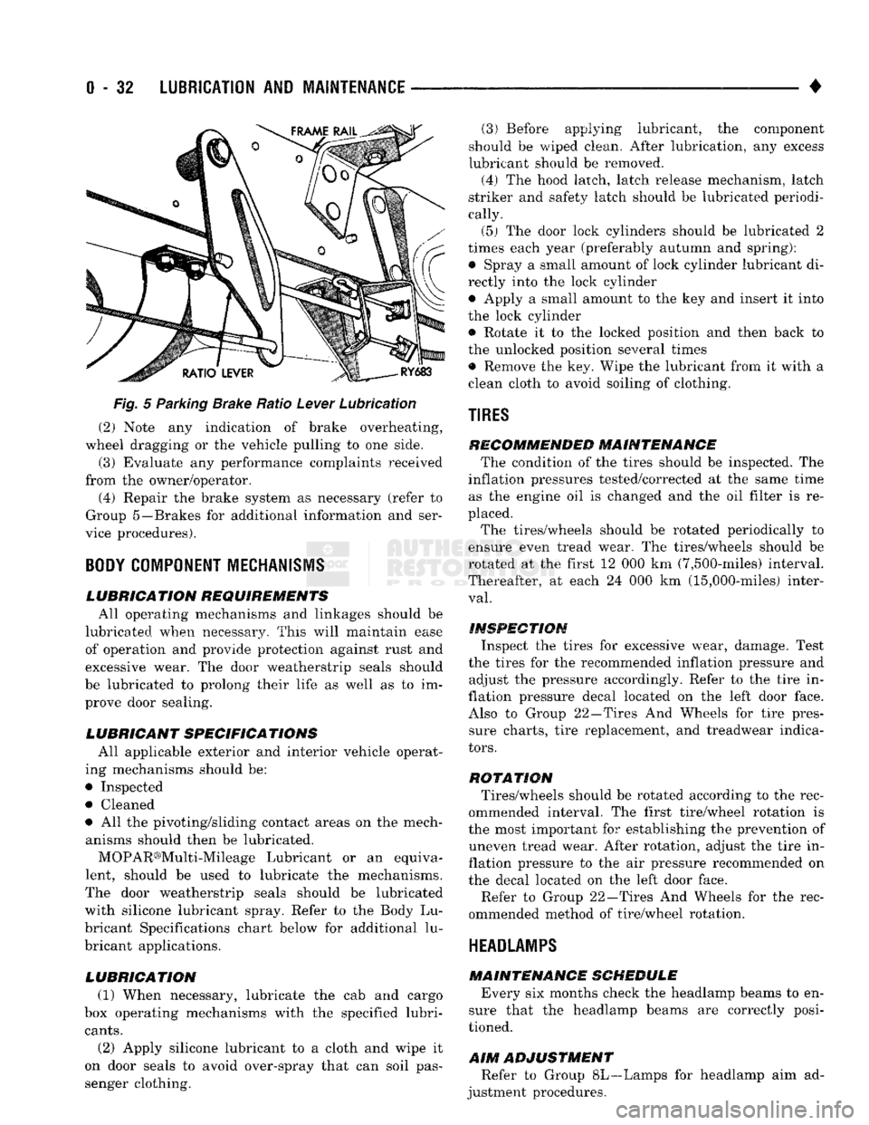
Fig.
5 Parking Brake Ratio Lever Lubrication (2) Note any indication of brake overheating,
wheel dragging or the vehicle pulling to one side.
(3) Evaluate any performance complaints received
from the owner/operator. (4) Repair the brake system as necessary (refer to
Group 5—Brakes for additional information and ser
vice procedures).
BODY
COMPONENT
MECHANISMS
LUBRICATION REQUIREMENTS
All operating mechanisms and linkages should be
lubricated when necessary. This will maintain ease of operation and provide protection against rust and
excessive wear. The door weatherstrip seals should
be lubricated to prolong their life as well as to im prove door sealing.
LUBRICANT SPECIFICATIONS
All applicable exterior and interior vehicle operat
ing mechanisms should be:
• Inspected • Cleaned
• All the pivoting/sliding contact areas on the mech anisms should then be lubricated.
MOPAR®Multi-Mileage Lubricant or an equiva
lent, should be used to lubricate the mechanisms.
The door weatherstrip seals should be lubricated
with silicone lubricant spray. Refer to the Body Lu
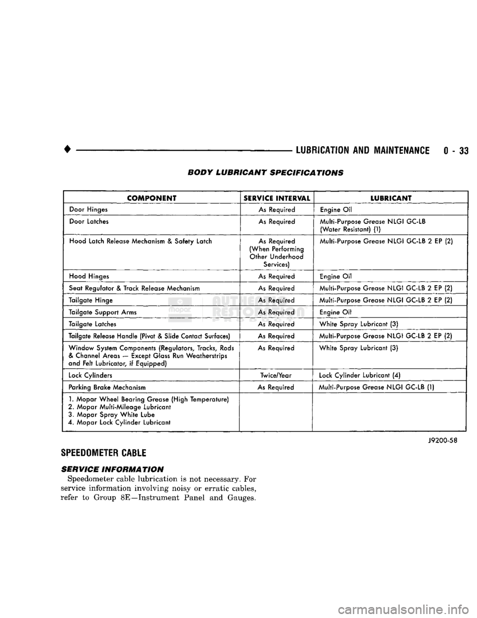
bricant Specifications chart below for additional lu
bricant applications.
LUBRICATION
(1) When necessary, lubricate the cab and cargo
box operating mechanisms with the specified lubri
cants.
(2) Apply silicone lubricant to a cloth and wipe it
on door seals to avoid over-spray that can soil pas
senger clothing. (3) Before applying lubricant, the component
should be wiped clean. After lubrication, any excess
lubricant should be removed.
(4) The hood latch, latch release mechanism, latch
striker and safety latch should be lubricated periodi
cally.
(5) The door lock cylinders should be lubricated 2
times each year (preferably autumn and spring): • Spray a small amount of lock cylinder lubricant di
rectly into the lock cylinder
• Apply a small amount to the key and insert it into
the lock cylinder • Rotate it to the locked position and then back to
the unlocked position several times
• Remove the key. Wipe the lubricant from it with a
clean cloth to avoid soiling of clothing.
TIRES
RECOMMENDED MAINTENANCE
The condition of the tires should be inspected. The
inflation pressures tested/corrected at the same time as the engine oil is changed and the oil filter is re
placed.
The tires/wheels should be rotated periodically to
ensure even tread wear. The tires/wheels should be
rotated at the first 12 000 km (7,500-miles) interval.
Thereafter, at each 24 000 km (15,000-miles) inter
val.
INSPECTION
Inspect the tires for excessive wear, damage. Test
the tires for the recommended inflation pressure and adjust the pressure accordingly. Refer to the tire in
flation pressure decal located on the left door face. Also to Group 22—Tires And Wheels for tire pressure charts, tire replacement, and treadwear indica
tors.
ROTATION
Tires/wheels should be rotated according to the rec
ommended interval. The first tire/wheel rotation is
the most important for establishing the prevention of uneven tread wear. After rotation, adjust the tire in
flation pressure to the air pressure recommended on
the decal located on the left door face.
Refer to Group 22—Tires And Wheels for the rec
ommended method of tire/wheel rotation.
HEADLAMPS
MAINTENANCE SCHEDULE
Every six months check the headlamp beams to en
sure that the headlamp beams are correctly posi
tioned.
AIM
ADJUSTMENT
Refer to Group 8L—Lamps for headlamp aim ad
justment procedures.
Page 52 of 1502
•
LUBRICATION
AND
MAINTENANCE
0 - 33 BODY LUBRICANT SPECIFICATIONS
COMPONENT
SERVICE
INTERVAL
LUBRICANT
Door
Hinges
As
Required
Engine
Oil
Door
Latches
As
Required Multi-Purpose Grease
NLGI
GC-LB
(Water
Resistant)
(1)
Hood
Latch Release Mechanism
&
Safety Latch
As
Required
(When Performing Other Underhood Services) Multi-Purpose Grease
NLGI
GC-LB
2
EP
(2)
Hood
Hinges
As
Required
Engine
Oil
Seat Regulator
&
Track Release Mechanism
As
Required Multi-Purpose Grease
NLGI
GC-LB
2
EP
(2)
Tailgate Hinge
As
Required Multi-Purpose Grease
NLGI
GC-LB
2
EP
(2)
Tailgate Support Arms
As
Required
Engine
Oil
Tailgate Latches
As
Required
White
Spray Lubricant
(3)
Tailgate Release Handle (Pivot & Slide Contact Surfaces)
As
Required Multi-Purpose Grease
NLGI
GC-LB
2
EP
(2)
Window System Components (Regulators, Tracks,
Rods
&
Channel Areas — Except
Glass
Run Weatherstrips
and
Felt
Lubricator,
if
Equipped)
As
Required
White
Spray Lubricant
(3)
Lock
Cylinders Twice/Year
Lock
Cylinder Lubricant
(4)
Parking Brake Mechanism
As
Required Multi-Purpose Grease
NLGI
GC-LB
(1)
1.
Mopar
Wheel
Bearing Grease (High
Temperature)
2. Mopar Multi-Mileage Lubricant 3. Mopar Spray
White
Lube
4. Mopar Lock Cylinder Lubricant
J9200-58
SPEEDOMETER
CABLE
SERVICE INFORMATION Speedometer cable lubrication is not necessary. For
service information involving noisy or erratic cables,
refer to Group 8E—Instrument Panel and Gauges.
Page 323 of 1502

8A
- 2
ELECTRICAL
•
MALFUNCTION
INDICATOR
LAMP
DIAGNOSTIC SCAN
TOOL
POWERTRAIN CONTROL
MODULE
GENERATOR
BATTERY
J938A-23
Fig.
2
Charging
System
Components—Typical
BATTERY TEST
PROCEDURES
INDEX
page
Battery
Charging
6
Battery
Load Test
5
Battery
Open
Circuit
Voltage Test
.............
4
Causes
of
Battery
Discharging
3
GENERAL
INFORMATION
The battery stores, stabilizes,
and
produces electri
cal current.
A
battery must
be
able
to
accept
a
charge
and
produce high-amperage current over
an
extended period.
A
chemical reaction takes place
be
tween sulfuric acid solution (electrolyte)
and
lead + /-
plates
in
each cell
of the
battery.
As the
battery discharges,
the
plates collect acid from
the
electro
lyte.
When
the
charging system charges
the
battery,
water
is
converted
to
sulfuric acid
in the
battery.
The
amount
of
acid (specific gravity)
in the
electrolyte
can
be
measured with
a
hydrometer.
A
factory
in
stalled battery
has a
built-in test indicator
to
help
determine state-of-charge.
The
factory installed bat
tery
is
also nonrefillable, water
can not be
added.
The battery
is
vented
to
release gases that
are cre-
page
General
Information
2
Ignition
Off
Draw (IOD)
4
State
of
Charge Test Using Test
Indicator
.......
3
Test
Indicator
3
ated when
the
battery
is
being charged.
The
battery
top,
posts,
and
terminals should
be
cleaned when other underhood maintenance
is
performed (Fig.
3).
WARNING:
DO
NOT
ATTEMPT
TO
ASSIST BOOST, CHARGE,
OR
TEST BATTERY WHEN ELECTROLYTE LEVEL IS BELOW THE TOP
OF
THE PLATES
(YELLOW
OR
BRIGHT COLOR
IS
VISIBLE). PER
SONAL
INJURY
MAY
OCCUR.
When
the
electrolyte level
is
below
the top of the
plates (yellow
or
bright indicator),
the
battery must
be replaced.
The
battery must
be
completely charged (green indicator)
and the top,
posts,
and
terminals
should
be
properly cleaned before diagnostic proce
dures
are
performed. Refer
to
Group
8B -
Battery/ Starter Service,
for
additional information.
Page 397 of 1502
8E - 16 INSTRUMENT PANEL AND GAUGES
• SWITCH AND
PANEL
COMPONENT
SERVICE
INDEX
page
Ash
Tray
20
Cigar
Lighter
........................ 20
Four
Wheel Drive
Indicator
19
Fuse
Block
and
Flashers
................... 19
Glove
Box 21
Heater A/C Control
17
page
Heater Control
16
Hood
Release
19
Illumination
Bulb Replacement
22
Message
Center Module
................... 18
Steering Column Lowering
and
Raising
16
Switches
17
DISCONNECT NEGATIVE CABLE FEOM
BATTERY IN ENGINE COMPAETMENT BE FORE SERVICING INSTRUMENT PANEL.
STEERING COLUMN LOWERING AND RAISING When servicing the instrument panel and the Low
ering and Raising of the steering column is required,
the following is the procedure for doing so: This procedure is not for removing and replac
ing the steering column. Refer to Group - 19 Steering of this manual for the removal and re
placement procedures.
LOWERING STEERING COLUMN
(1) Disconnect negative cable from battery.
(2)
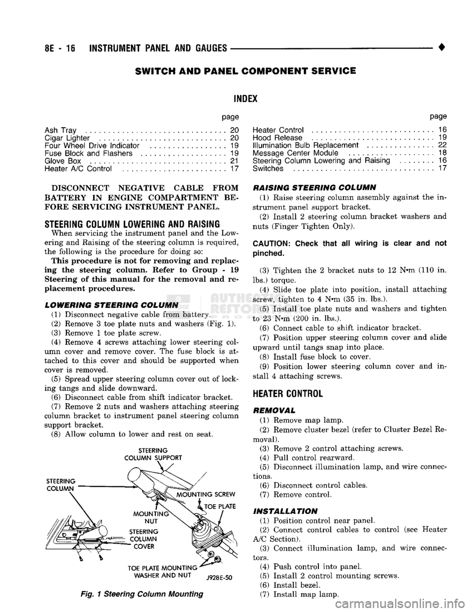
Remove 3 toe plate nuts and washers (Fig. 1).
(3) Remove 1 toe plate screw.
(4) Remove 4 screws attaching lower steering col
umn cover and remove cover. The fuse block is at
tached to this cover and should be supported when cover is removed.
(5) Spread upper steering column cover out of lock
ing tangs and slide downward.
(6)
Disconnect cable from shift indicator bracket.
(7)
Remove 2 nuts and washers attaching steering
column bracket to instrument panel steering column support bracket.
(8)
Allow column to lower and rest on seat.
STEERING
COLUMN SUPPORT
WASHER
AND NUT
Fig.
1 Steering
Column
Mounting
RAISING STEERING COLUMN
(1) Raise steering column assembly against the in
strument panel support bracket. (2) Install 2 steering column bracket washers and
nuts (Finger Tighten Only).
CAUTION:
Check that
all
wiring
is
clear
and not
pinched.
(3) Tighten the 2 bracket nuts to 12 Nnn-(110 in.
lbs.) torque. (4) Slide toe plate into position, install attaching
screw, tighten to 4 N®m (35 in. lbs.).
(5) Install toe plate nuts and washers and tighten
to 23 N*m (200 in. lbs.).
(6)
Connect cable to shift indicator bracket.
(7)
Position upper steering column cover and slide
upward until tangs snap into place.
(8) Install fuse block to cover.
(9)
Position lower steering column cover and in
stall 4 attaching screws.
HEATER CONTROL
REMOVAL
(1) Remove map lamp.
(2) Remove cluster bezel (refer to Cluster Bezel Re
moval). (3) Remove 2 control attaching screws. (4) Pull control rearward.
(5) Disconnect illumination lamp, and wire connec
tions.
(6)
Disconnect control cables.
(7)
Remove control.
INSTALLATION
(1) Position control near panel.
(2) Connect control cables to control (see Heater
A/C Section). (3) Connect illumination lamp, and wire connec
tors.
(4) Push control into panel.
(5) Install 2 control mounting screws.
(6)
Install bezel.
(7)
Install map lamp.
Page 400 of 1502
•
INSTRUMENT PANEL
AND
GAUGES
8E - 19
MESSAGE
CENTER
PRINTED CIRCUIT BOARD
J918E-33
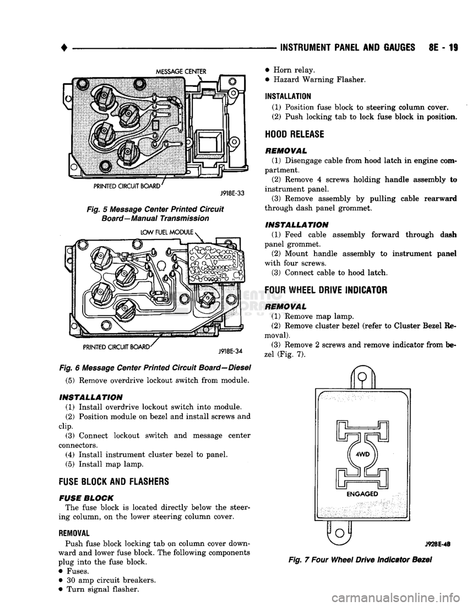
Fig.
5
Message
Center Printed Circuit
Board—Manual
Transmission
LOW FUEL MODULE
>
PRINTED CIRCUIT BOARD
J918E-34
Fig.
6
Message
Center Printed Circuit
Board—Diesel
(5) Remove overdrive lockout switch from module.
INSTALLATION
(1) Install overdrive lockout switch into module.
(2) Position module on bezel and install screws and
clip.
(3) Connect lockout switch and message center
connectors.
(4) Install instrument cluster bezel to panel.
(5) Install map lamp.
FUSE
BLOCK AND
FLASHERS
FUSE
BLOCK
The fuse block is located directly below the steer
ing column, on the lower steering column cover.
REMOVAL
Push fuse block locking tab on column cover down
ward and lower fuse block. The following components
plug into the fuse block.
• Fuses. • 30 amp circuit breakers.
• Turn signal flasher. • Horn relay.
• Hazard Warning Flasher.
INSTALLATION
(1) Position fuse block to steering column cover. (2) Push locking tab to lock fuse block in position.
HOOD
RELEASE
REMOVAL
(1) Disengage cable from hood latch in engine com
partment. (2) Remove 4 screws holding handle assembly to
instrument panel.
(3) Remove assembly by pulling cable rearward
through dash panel grommet.
INSTALLATION
(1) Feed cable assembly forward through dash
panel grommet.
(2) Mount handle assembly to instrument panel
with four screws.
(3) Connect cable to hood latch.
FOUR
WHEEL
DRIVE
INDICATOR
REMOVAL
(1) Remove map lamp.
(2) Remove cluster bezel (refer to Cluster Bezel Re
moval).
(3) Remove 2 screws and remove indicator from be
zel (Fig. 7).
o
J928E-48
Fig.
7
Four
Wheel
Drive Indicator
Bezel
Page 625 of 1502
TRANSFER
CASE
INSULATOR
MOUNTING PLATE
NUT(B
RAIL
ASSEMBLY
SPACER
UPPER
INSULATOR
NUT®
LOWER
INSULATOR
J9109-242
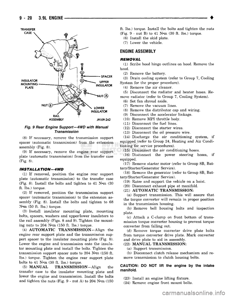
Fig.
9 Rear
Engine
Support—4WD
with
Manual
Transmission
(8) If necessary, remove the transmission support
spacer (automatic transmission) from the extension
assembly (Fig. 8).
(9) If necessary, remove the engine rear support
plate (automatic transmission) from the transfer case (Fig. 8).
INSTALLATION-4WD
(1) If removed, position the engine rear support
plate (automatic transmission) to the transfer case (Fig. 8). Install the bolts and tighten to 41 N-m (30
ft. lbs.) torque.
(2) If removed, position the transmission support
spacer (automatic transmission) to the extension as
sembly (Fig. 8). Install the bolts and tighten to 68 N-m (50 ft. lbs.) torque.
(3) Install insulator mounting plate, mounting
bolts,
spacers, washers and upper/lower insulators to
the rail assembly (Figs. 8 and 9). Tighten the mount
ing nuts to 204 N*m (150 ft. lbs.) torque.
(4) AUTOMATIC TRANSMISSION-Align the
engine rear support plate and the transmission sup
port spacer to the insulator mounting plate (Fig. 8). Lower the engine and transmission onto the insula
tor mounting plate and install the bolts. Tighten the transmission support spacer nuts to 204 N-m (150 ft. lbs.) torque. Tighten the engine rear support plate
bolts to 41 N-m (30 ft. lbs.) torque.
(5) MANUAL TRANSMISSION—Align the
transfer case to the insulator mounting plate and lower the engine and transmission. Install the bolts and tighten the nuts (Fig. 9 - nut A) to 204 N-m (150 ft. lbs.) torque. Install the bolts and tighten the nuts
(Fig. 9 - nut B) to 41 N-m (30 ft. lbs.) torque. (6) Install the skid plate.
(7) Lower the vehicle.
ENGINE
ASSEMBLY
REMOVAL (1) Scribe hood hinge outlines on hood. Remove the
hood.
(2) Remove the battery. (3) Drain cooling system (refer to Group 7, Cooling
System for the proper procedure).
(4) Remove the air cleaner. (5) Disconnect the radiator and heater hoses. Re
move radiator (refer to Group 7, Cooling System).
(6) Set fan shroud aside. (7) Remove the vacuum lines. (8) Remove the distributor cap and wiring.
(9) Disconnect the accelerator linkage.
(10) Remove MPI throttle body. (11) Disconnect the fuel lines. (12) Disconnect the starter wires.
(13) Disconnect the oil pressure wire. (14) Discharge the air conditioning system, if
equipped (refer to Group 24, Heating and Air Condi
tioning for service procedures). (15) Disconnect the air conditioning hoses.
(16) Disconnect the power steering hoses, if
equipped. (17) Remove starter motor (refer to Group 8B, Bat
tery/Starter/Generator Service). (18) Remove the generator (refer to Group 8B, Bat
tery/Starter/Generator Service).
(19) Raise and support the vehicle on a hoist.
(20) Disconnect exhaust pipe at manifold.
(21) AUTOMATIC TRANSMISSION: (a) Support transmission. This will assure that
the torque converter will remain in proper position in the transmission housing. (b) Remove bell housing bolts and inspection
plate.
(c) Attach a C-clamp on front bottom of trans
mission torque converter housing to prevent torque
converter from falling out.
(d) Remove torque converter drive plate bolts
from torque converter drive plate. Mark converter and drive plate to aid in assembly.
(22) MANUAL TRANSMISSION: (a) Support transmission.
(b) Disconnect clutch release mechanism and re
move transmission to clutch housing bolts.
CAUTION:
DO NOT
lift
the engine by the intake
manifold.
(23) Install an engine lifting fixture.
(24) Remove engine front mount bolts.
Page 626 of 1502
•
3.9L
ENGINE
9 - 21 (25) Lower the vehicle.
(26) On automatic transmission vehicles, discon
nect the engine from the torque converter drive
plate. On manual transmission vehicles, move engine forward until drive pinion shaft clears the clutch
disc.
Remove engine from engine compartment. (27) Install engine assembly on engine repair
stand.
INSTALLATION (1) Remove engine from the repair stand and posi
tion in the engine compartment.
(2) Install engine support fixture.
(3) Raise and support the vehicle on a hoist.
(4)
AUTOMATIC TRANSMISSION: (a) Position the torque converter and drive plate.
Install torque converter drive plate bolts. Tighten
the bolts to 31 Nnn (270 in. lbs.) torque.
(b) Install the engine front mounts.
(c) Install bell housing bolts. Tighten the bolts to
41 N-m (30 ft. lbs.) torque.
(d) Remove C-clamp.
(e) Install the inspection plate.
(5) MANUAL TRANSMISSION: (a) Position the drive pinion shaft to the clutch
disc.
(b) Connect the clutch release mechanism and
install the transmission to clutch bolts. Tighten the
bolts to 68 N-m (50 ft. lbs.) torque.
(c) Install the engine front mounts.
(6) Remove transmission support.
(7) Install exhaust pipe to manifold.
(8) Lower the vehicle.
(9) Remove engine lifting fixture.
(10) Install the generator (refer to Group 8B, Bat
tery/Starter/Generator Service). (11) Install starter motor (refer to Group 8B, Bat
tery/Starter/Generator Service). (12) Connect power steering hoses, if equipped.
(13) Connect air conditioning hoses.
(14) Evacuate and charge the air conditioning sys
tem, if equipped (refer to Group 24, Heater and Air Conditioning for service procedures). (15) Using a new gasket, install MPI throttle body.
Tighten the throttle body bolts to 23 N-m (200 in. lbs.) torque. (16) Connect the accelerator linkage.
(17) Connect the starter wires. (18) Connect the oil pressure wire.
(19) Install the distributor cap and wiring.
(20) Connect the vacuum lines.
(21) Connect the fuel lines.
(22) Install the radiator (refer to Group 7, Cooling
System). Connect the radiator hoses and heater
hoses.
(23) Install fan shroud in position. (24) Fill cooling system (refer to Group 7, Cooling
System for the proper procedures). (25) Install the air cleaner.
(26) Install the battery.
(27) Warm engine and adjust.
(28) Install hood and line up with the scribe
marks. (29) Road test vehicle.
CYLINDER
HEAD COVER
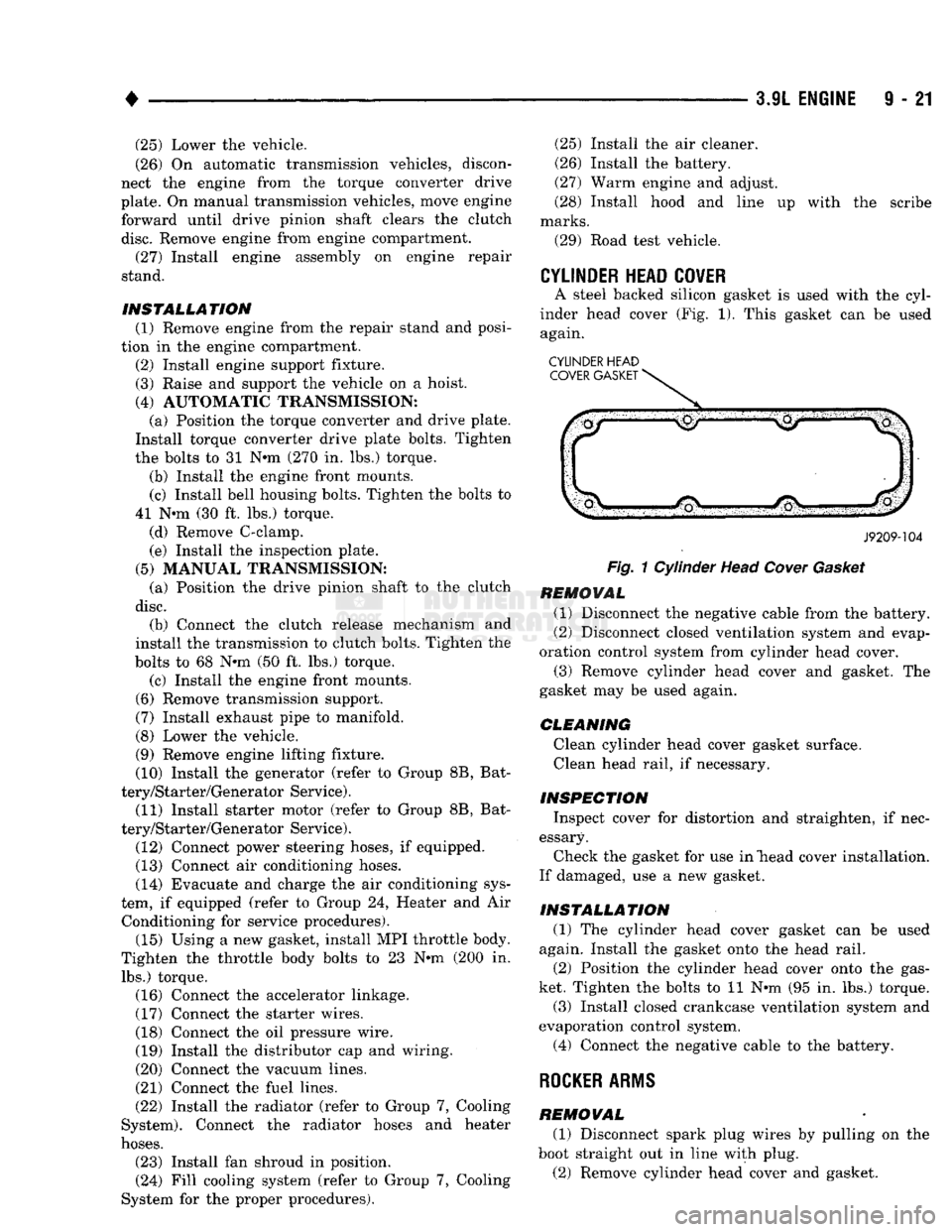
A steel backed silicon gasket is used with the cyl
inder head cover (Fig. 1). This gasket can be used again.
CYLINDER HEAD COVER GASKET
J9209-104
Fig.
1 Cylinder Head
Cover
Gasket
REMOVAL (1) Disconnect the negative cable from the battery.
(2) Disconnect closed ventilation system and evap
oration control system from cylinder head cover. (3) Remove cylinder head cover and gasket. The
gasket may be used again.
CLEANING Clean cylinder head cover gasket surface. Clean head rail, if necessary.
INSPECTION Inspect cover for distortion and straighten, if nec
essary. Check the gasket for use in "head cover installation.
If damaged, use a new gasket.
INSTALLATION (1) The cylinder head cover gasket can be used
again. Install the gasket onto the head rail.
(2) Position the cylinder head cover onto the gas
ket. Tighten the bolts to 11 N-m (95 in. lbs.) torque. (3) Install closed crankcase ventilation system and
evaporation control system.
(4) Connect the negative cable to the battery.
ROCKER
ARMS
REMOVAL (1) Disconnect spark plug wires by pulling on the
boot straight out in line with plug.
(2) Remove cylinder head cover and gasket.
Page 655 of 1502
TRANSFER
CASE
TRANSFER
CASE
ENGINE
REAR
SUPPORT PLATE
EXTENSION
ASSEMBLY
TRANSMISSION
SUPPORT
SPACER
SPACER
UPPER
INSULATOR
INSULATOR
MOUNTING
PLATE
LOWER
INSULATOR
fT^RAIL
J9109-244
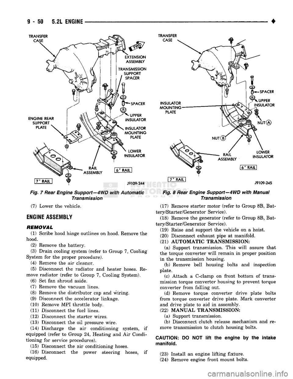
Fig,
7 Rear Engine Support—4WD
with
Automatic
Transmission
(7)
Lower the vehicle.
ENGINE
ASSEMBLY
REMOVAL
(1) Scribe hood hinge outlines on hood. Remove the
hood. (2) Remove the battery.
(3) Drain cooling system (refer to Group 7, Cooling
System for the proper procedure). (4) Remove the air cleaner.
(5) Disconnect the radiator and heater hoses. Re
move radiator (refer to Group 7, Cooling System). (6) Set fan shroud aside.
(7)
Remove the vacuum lines.
(8) Remove the distributor cap and wiring.
(9) Disconnect the accelerator linkage.
(10) Remove MPI throttle body.
(11) Disconnect the fuel lines.
(12) Disconnect the starter wires.
(13) Disconnect the oil pressure wire.
(14) Discharge the air conditioning system, if
equipped (refer to Group 24, Heating and Air Condi
tioning for service procedures).
(15) Disconnect the air conditioning hoses.
(16) Disconnect the power steering hoses, if
equipped.
INSULATOR
MOUNTING
PLATE
SPACER
UPPER
L\ f
INSULATOR
NUT®
RAIL
ASSEMBLY
LOWER
INSULATOR
l6ff
RAIL
I
J9109-245
Fig.
8 Rear
Engine
Support—4WD
with
Manual
Transmission
(17) Remove starter motor (refer to Group 8B, Bat
tery/Starter/Generator Service).
(18) Remove the generator (refer to Group 8B, Bat
tery/Starter/Generator Service).
(19) Raise and support the vehicle on a hoist.
(20) Disconnect exhaust pipe at manifold.
(21)
AUTOMATIC TRANSMISSION: (a) Support transmission. This will assure that
the torque converter will remain in proper position in the transmission housing. (b) Remove bell housing bolts and inspection
plate. (c) Attach a C-clamp on front bottom of trans
mission torque converter housing to prevent torque
converter from falling out. (d) Remove torque converter drive plate bolts
from torque converter drive plate. Mark converter and drive plate to aid in assembly.
(22)
MANUAL TRANSMISSION; (a) Support transmission.
(b) Disconnect clutch release mechanism and re
move transmission to clutch housing bolts.
CAUTION:
manifold.
DO
NOT lift the
engine
by the
intake
(23) Install an engine lifting fixture.
(24) Remove engine front mount bolts.