1993 DODGE TRUCK ground clearance
[x] Cancel search: ground clearancePage 31 of 1502

0 - 12
LUBRICATION
AND
MAINTENANCE
• A vehicle equipped with SAE approved sling-type
towing equipment can be used (Fig. 10). However,
many vehicles are equipped with air dams, spoilers, and/or ground effect panels. In this case a wheel-lift
towing vehicle or a flat-bed hauling vehicle is recom mended (Fig. 10). If a flat bed device is used, the ap
proach angle should not exceed 15 degrees.
GROUND CLEARANCE The lifted wheels of the disabled vehicle should be
a minimum of 10 cm (4 in.) off the ground. Make
sure there is enough clearance at the opposite end.
This is critical when towing over rough terrain. If necessary, the rear ground clearance can be increased by removing the wheels from the lifted end
and then towing with the lifted end closer to the
ground. If the rear wheels are removed, secure the
brake drums. A 20 cm (8 in.) ground clearance must
be maintained between brake drums or rotors and the ground.
SAFETY PRECAUTIONS The following safety precautions must be consid
ered when preparing for and during a vehicle towing operation:
• Remove exhaust pipe tips that interfere with the
tow sling and crossbar • Padding should be placed between the tow sling/
crossbar and any painted surfaces
• If the vehicle is damaged, secure the loose and pro
truding parts
• Always use a safety chain system that is indepen dent of the lifting and towing equipment
• When placing tow hooks on the rear axle, position them so they do not damage the brake tubing or
hoses
• Do not allow any of the towing equipment to con
tact the fuel tank
• Do not tow the vehicle by connecting to the front
or rear shock absorbers
• The operator should not go under a vehicle while
it is lifted by the towing equipment. The vehicle
should first be supported by safety stands
• Do not allow passengers in a vehicle being towed
• Observe all state and local laws involving warning signals, night illumination, speed, etc.
• Do not exceed a towing speed of 48 km/h (30 mph)
• Avoid towing distances of more than 24 km (15
miles) whenever possible • Do not attach tow chains or a tow sling to a
bumper, the steering linkage, the universal joints, or a drive shaft
REAR-END RAISED TOWING It is recommended that the rear-end raised towing
method be used. Vehicles can be towed with the front
wheels on the ground for extended distances at speeds not exceeding 48 km/h (30 mph) (Fig. 11). (1) Attach the J-hooks around the axle shaft tubes
outboard of the rear springs. (2) Position and center the sling under and for
ward of the rear bumper. (3) Attach safety chains (with pads) at each end of
the rear bumper.
(4) Turn the ignition switch to the OFF position to
unlock the steering wheel. (5) Clamp the steering wheel with the front wheels
in the straight ahead position.
CAUTION:
Do not use the steering
column
lock
to
secure
front
wheel
in the straight-ahead
position.
(6) Shift the transmission to NEUTRAL.
POSITION CENTER BAR FORWARD
OF
BUMPER
-
/
J-HOOKS OUTBOARD
OF
SPRINGS
RN967A
Fig. 11 Rear-End
Raised
Towing
FRONT'END RAISED TOWING If a vehicle cannot be towed from the rear, the
front-end raised towing method normally can be
used (Fig. 12). (1) Center the sling with the bumper and position
it at the frame front crossmember.
CAUTION:
Use tow
chains
with
J-hooks
for
con
necting
to the
disabled
vehicle's
lower
suspension
arms.
Never use
T-hooks.
(2) Route the J-hooks and tow chains over the
steering linkage outboard of the coil spring.
(3) Attach the J-hooks to the outer end of the
lower suspension arms.
(4) Raise the vehicle.
(5.) Attach the safety chains to the disabled vehicle
at the frame rails.
Vehicles equipped with a MANUAL TRANSMIS
SION can be towed with the rear wheels on the
Page 279 of 1502

7 - 8
COOLING
SYSTEM
COOLING SYSTEM DIAGNOSIS (EXCEPT DIESEL)—CONTINUED
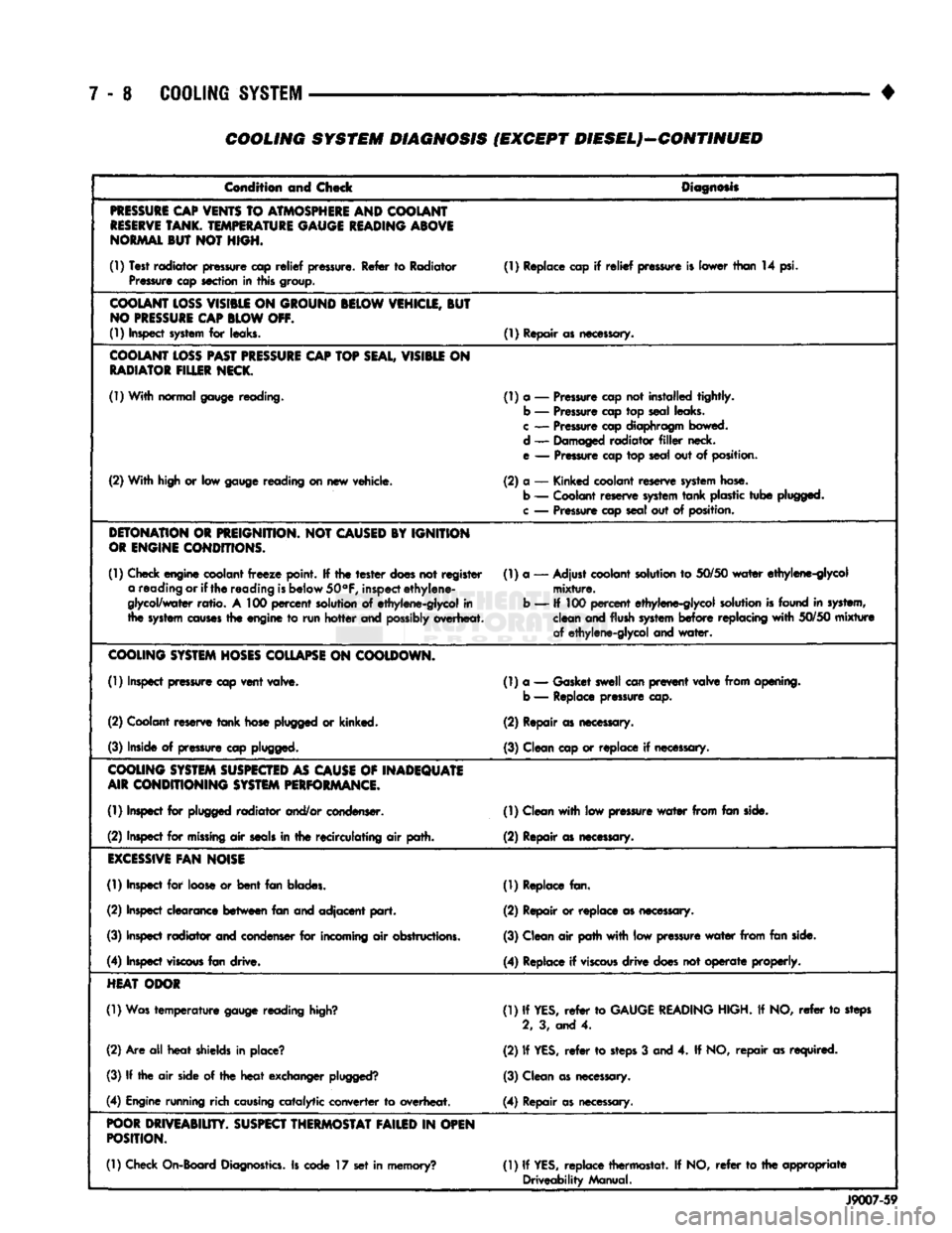
Condition and Check
Diagnosis
PRESSURE
CAP
VENTS
TO
ATMOSPHERE
AND COOLANT
RESERVE
TANK.
TEMPERATURE
GAUGE
READING
ABOVE
NORMAL
BUT NOT HIGH.
(1) Test radiator pressure cap
relief
pressure. Refer to Radiator Pressure cap section in this group. (1) Replace cap if
relief
pressure is lower than 14 psi.
COOLANT
LOSS
VISIBLE
ON
GROUND
BELOW
VEHICLE,
BUT
NO
PRESSURE
CAP
BLOW
OFF.
(1) Inspect
system
for leaks. (1) Repair as necessary.
COOLANT
LOSS
PAST
PRESSURE
CAP
TOP
SEAL,
VISIBLE
ON
RADIATOR
FILLER
NECK.
(1) With normal gauge reading. (1) a — Pressure cap not installed tightly.
b — Pressure cap top seal leaks.
c
— Pressure cap diaphragm bowed.
d — Damaged radiator
filler
neck.
e — Pressure cap top seal out of position.
(2) With high or low gauge reading on new vehicle. (2) a — Kinked coolant reserve
system
hose.
b — Coolant reserve
system
tank
plastic
tube
plugged,
c
— Pressure cap seal out of position.
DETONATION
OR
PREIGNITION.
NOT
CAUSED
BY IGNITION
OR
ENGINE
CONDITIONS.
(1) Check engine coolant
freeze
point. If the
tester
does
not register a reading or if
the
reading
is
below
50°F,
inspect
ethylene-
glycol/water
ratio.
A 100
percent
solution of ethylene-glycol in
the
system
causes
the engine to run
hotter
and
possibly
overheat. (1) a — Adjust coolant solution to
50/50
water
ethylene-glycol
mixture.
b — If 100
percent
ethylene-glycol solution
is
found in system, clean and flush
system
before
replacing
with
50/50
mixture
of ethylene-glycol and
water.
COOLING
SYSTEM
HOSES
COLLAPSE
ON
COOLDOWN.
(1) Inspect pressure cap
vent
valve. (1) a — Gasket swell can
prevent
valve from opening,
b — Replace pressure cap.
(2) Coolant reserve
tank
hose plugged or kinked. (2) Repair as necessary.
(3) Inside of pressure cap plugged. (3) Clean cap or replace if necessary.
COOLING
SYSTEM
SUSPECTED
AS
CAUSE
OF
INADEQUATE
AIR
CONDITIONING
SYSTEM
PERFORMANCE.
(1) Inspect for plugged radiator and/or condenser. (1) Clean
with
low pressure
water
from fan side.
(2) Inspect for
missing
air
seals
in the recirculating air path. (2) Repair as necessary.
EXCESSIVE
FAN
NOISE
(1) Inspect for loose or
bent
fan blades. (1) Replace fan.
(2) Inspect clearance
between
fan and adjacent
part.
(2) Repair or replace as necessary.
(3) Inspect radiator and condenser for incoming air obstructions. (3) Clean air path
with
low pressure
water
from fan side.
(4) Inspect
viscous
fan drive. (4) Replace if
viscous
drive
does not
operate
properly.
HEAT
ODOR
(1) Was
temperature
gauge reading
high?
(1) If
YES,
refer
to
GAUGE
READING
HIGH. If NO,
refer
to steps
2, 3, and 4.
(2) Are all
heat
shields in place? (2) If
YES,
refer
to
steps
3 and 4. If NO,
repair
as required.
(3) If the air side of the
heat
exchanger
plugged?
(3) Clean as necessary.
(4) Engine running rich
causing
catalytic converter to overheat. (4) Repair as necessary.
POOR
DRIVEABIUTY.
SUSPECT
THERMOSTAT
FAILED
IN
OPEN
POSITION.
(1) Check On-Board
Diagnostics.
Is code 17 set in memory? (1) If
YES,
replace thermostat. If NO,
refer
to the appropriate
Driveability Manual.
J9007-59
Page 450 of 1502

•
LAMPS
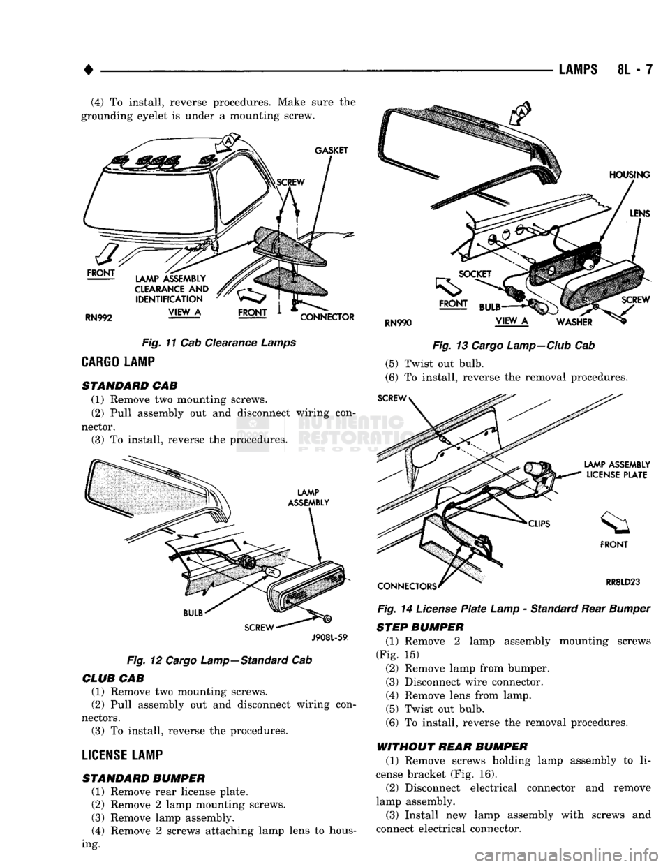
8L - 7 (4) To install, reverse procedures. Make sure the
grounding eyelet is under a mounting screw.
Fig.
11 Cab Clearance
Lamps
CARGO
LAMP
STANDARD
CAB (1) Remove two mounting screws. (2) Pull assembly out and disconnect wiring con
nector. (3) To install, reverse the procedures.
J908L-59.
Fig.
12
Cargo
Lamp—Standard Cab
CLUB
CAB (1) Remove two mounting screws.
(2) Pull assembly out and disconnect wiring con
nectors.
(3) To install, reverse the procedures.
LICENSE
LAMP
STANDARD BUMPER
(1) Remove rear license plate.
(2) Remove 2 lamp mounting screws.
(3) Remove lamp assembly. (4) Remove 2 screws attaching lamp lens to hous
ing.
Fig.
14
License
Plate
Lamp
- Standard Rear
Bumper
STEP BUMPER
(1) Remove 2 lamp assembly mounting screws
(Fig. 15)
(2) Remove lamp from bumper.
(3) Disconnect wire connector.
(4) Remove lens from lamp.
(5) Twist out bulb.
(6) To install, reverse the removal procedures.
WITHOUT REAR BUMPER (1) Remove screws holding lamp assembly to li
cense bracket (Fig. 16).
(2) Disconnect electrical connector and remove
lamp assembly.
(3) Install new lamp assembly with screws and
connect electrical connector.
Page 513 of 1502

8W
- 38
WIRING
DIAGRAMS
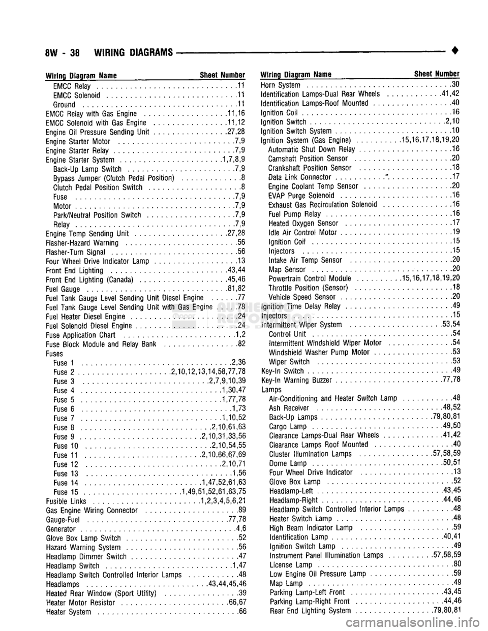
• Wiring Diagram Name Sheet Number
EMCC
Relay
11
EMCC
Solenoid
11
Ground
11
EMCC
Relay
with Gas
Engine
11,16
EMCC
Solenoid
with Gas
Engine
11,12
Engine
Oil
Pressure Sending
Unit
.27,28
Engine
Starter
Motor
7,9
Engine
Starter
Relay
.7,9
Engine
Starter
System 1,7,8,9 Back-Up Lamp
Switch
.7,9
Bypass
Jumper
(Clutch
Pedal
Position)
8
Clutch
Pedal
Position
Switch
8
Fuse
. 7,9
Motor
7,9
Park/Neutral
Position
Switch
. .7,9
Relay
7,9
Engine Temp Sending
Unit
.
.27,28
Flasher-Hazard Warning
.56
Flasher-Turn Signal
56
Four Wheel
Drive
Indicator
Lamp
13
Front
End
Lighting
. .
.43,44
Front
End
Lighting
(Canada) 45,46
Fuel
Gauge
81,82
Fuel
Tank Gauge
Level
Sending
Unit
Diesel Engine
77
Fuel
Tank Gauge
Level
Sending
Unit
with Gas
Engine
78
Fuel
Heater
Diesel Engine
24
Fuel
Solenoid Diesel Engine
.24
Fuse
Application
Chart
1,2
Fuse
Block Module
and
Relay Bank
82
Fuses
Fuse
1 2,36
Fuse
2
.........
2,10,12,13,14,58,77,78
Fuse
3
2,7,9,10,39
Fuse
4
1,30,47
Fuse
5
1,77,78
Fuse
6
......
.1,73
Fuse
7
1,10,52
Fuse
8
.2,10,61,63
Fuse
9
.2,10,31,33,56
Fuse
10
.2,10,54,55
Fuse
11
2,10,66,67,69
Fuse
12
2,10,71
Fuse
13 1,56
Fuse
14
1,47,52,61,63
Fuse
15
1,49,51,52,61,63,75
Fusible Links 1,2,3,4,5,6,21
Gas
Engine
Wiring
Connector
89
Gauge-Fuel .77,78
Generator
.4,6
Glove
Box
Lamp
Switch
52
Hazard Warning System
. .56
Headlamp Dimmer
Switch
47
Headlamp
Switch
1,47
Headlamp
Switch
Controlled
Interior
Lamps
Headlamps 43,44,
Heated
Rear Window
(Sport
Utility)
Heater
Motor
Resistor
Heater
System Wiring Diagram Name Sheet Number
Horn System
30
Identification
Lamps-Dual Rear Wheels
41,42
Identification
Lamps-Roof Mounted
. 40
Ignition
Coil
.16
Ignition
Switch
.2,10
Ignition
Switch
System
10
Ignition
System (Gas Engine)
.........
.15,16,17,18,19,20
Automatic
Shut Down Relay
.16
Camshaft
Position
Sensor
20
Crankshaft
Position
Sensor
.18
Data
Link
Connector
* . . .17
Engine Coolant Temp
Sensor
20
EVAP
Purge Solenoid
16
Exhaust Gas
Recirculation
Solenoid
16
Fuel
Pump Relay
.16
Heated
Oxygen
Sensor
. . . 17
Idle
Air
Control
Motor
.19
Ignition
Coil
.15
Injectors
.15
Intake
Air
Temp
Sensor
. .20
Map
Sensor
. .20
Powertrain
Control
Module .15,16,17,18,19,20
Throttle
Position
(Sensor)
.18
Vehicle
Speed
Sensor
.20
Ignition
Time
Delay Relay
49
Injectors
.15 Intermittent
Wiper
System .53,54
Control
Unit
.54 Intermittent
Windshield
Wiper
Motor
54
Windshield
Washer Pump
Motor
53
Wiper
Switch
53
Key-In
Switch
49
Key-In Warning Buzzer 77,78
Lamps
Air-Conditioning
and
Heater
Switch
Lamp
48
Ash
Receiver .48,52 Back-Up Lamps
......
79,80,81
Cargo Lamp
.
.49,50 Clearance Lamps-Dual Rear Wheels .41,42
Clearance Lamps Roof Mounted
.40
Cluster
Illumination
Lamps
.
.57,58,59
Dome Lamp
50,51
Four Wheel
Drive
Indicator
.13
Glove
Box
Lamp
52
Headlamp-Left
43,45 Headlamp-Right 44,46
Headlamp
Switch
Controlled
Interior
Lamps
. 48
Heater
Switch
Lamp
.48
High Beam
Indicator
Lamp
.59
Identification
Lamp
.
.40,41
Ignition
Switch
Lamp
.49
Instrument
Panel
Illumination
Lamps
.
.57,58,59
License Lamp
. . . 80
.
.48 Low
Engine
Oil
Pressure Lamp
59
45,46
Map
Lamp
49
.
.39
Parking
Lamp-Left
Front
43,45
66,67 Parking Lamp-Right
Front
44,46 .
.66
Rear
End
Lighting
System .79,80,81
Page 517 of 1502

8W
- 42
WIRING DIAGRAMS
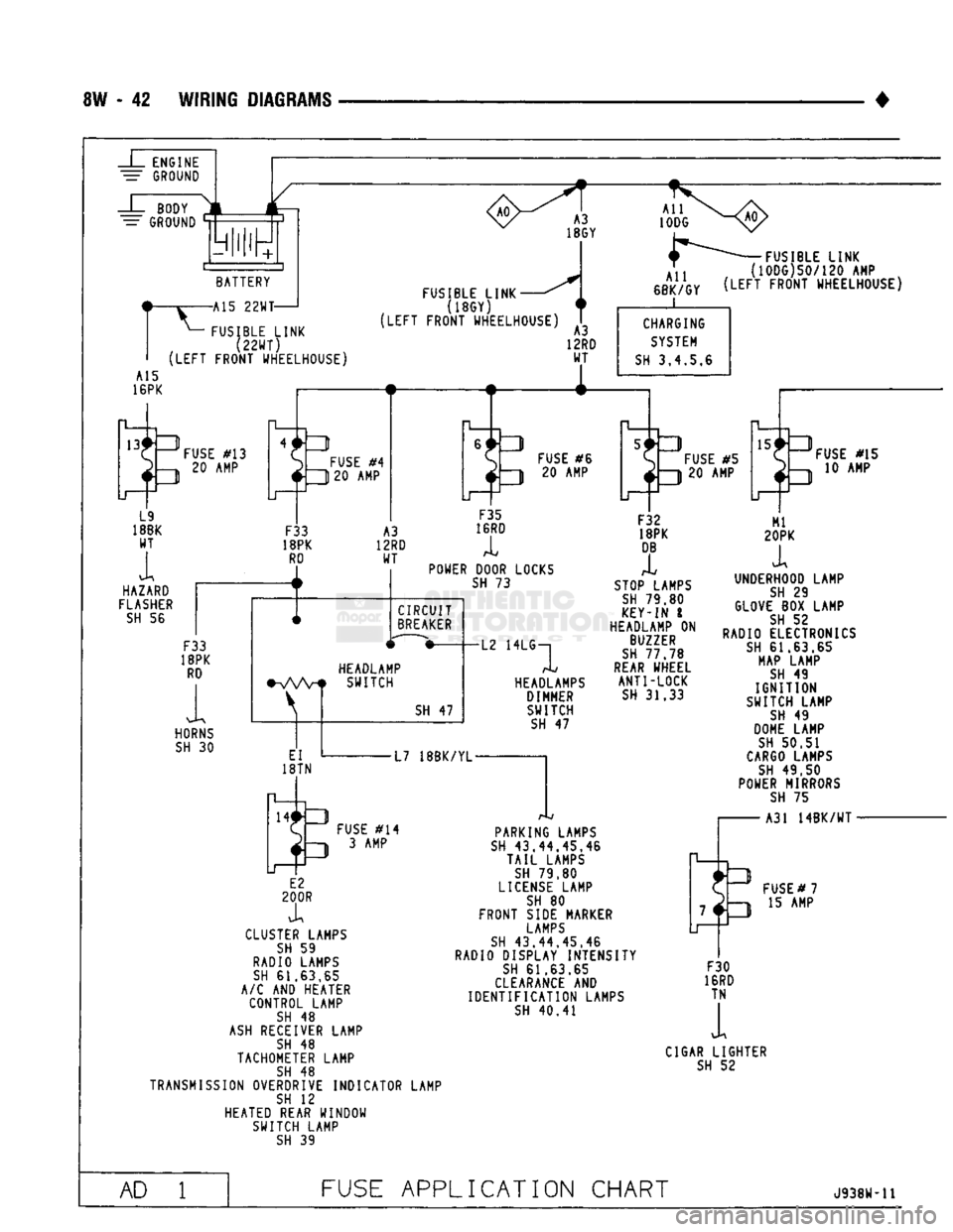
-J_
ENGINE
=
GROUND
BODY
—
GROUND
BATTERY
-A
15
22WT-
^—
FUSIBLE LINK
(22WT)
(LEFT
FRONT WHEELHOUSE) FUSIBLE LINK
(18GY)
(LEFT
FRONT WHEELHOUSE)
All
6BK/GY FUSIBLE LINK
{1000)50/120 AMP
(LEFT
FRONT WHEELHOUSE) A15
16PK
13#-ZI
L9
18BK WT
i
HAZARD
FLASHER
SH
56
IT-
FUSE
#13
20 AMP
O
FUSE
#4
|
ft 20 AMP
F33
18PK
RD
A3
12RD WT A3
12RD WT
4-
CHARGING
SYSTEM
SH
3,4,5.6
FUSE
#6 20 AMP
FUSE
#5
J—1| 20 AMP
F33
18PK
RD
HORNS
SH
30
POWER DOOR LOCKS
SH
73
CIRCUIT
BREAKER
HEADLAMP
•VWf
SWITCH
EI
18TN
SH
47
-L2 HEADLAMPS
DIMMER SWITCH
SH
47
F32
18PK
DB
I
STOP LAMPS
SH
79,80
KEY-IN
I
HEADLAMP
ON
BUZZER
SH
77.78
REAR
WHEEL ANTI-LOCK
SH
31.33
FUSE
#15
10 AMP
L7
18BK/YL-
3
FUSE
#14
D 3AMP
E2
200R
X
CLUSTER LAMPS
SH
59
RADIO LAMPS
SH
61.63.65
A/C
AND
HEATER CONTROL LAMP
SH
48
ASH
RECEIVER LAMP
SH
48
TACHOMETER LAMP
SH
48
TRANSMISSION OVERDRIVE INDICATOR LAMP
SH
12
HEATED REAR WINDOW SWITCH LAMP
SH
39
PARKING LAMPS
SH
43.44.45,46
TAIL
LAMPS
SH
79.80
LICENSE
LAMP
SH
80
FRONT SIDE MARKER
LAMPS
SH
43.44.45.46
RADIO DISPLAY INTENSITY
SH
61.63.65
CLEARANCE
AND
IDENTIFICATION
LAMPS
SH
40.41
UNDERHOOD LAMP
SH
29
GLOVE
BOX
LAMP
SH
52
RADIO ELECTRONICS
SH
61.63.65
MAP LAMP
SH
49
IGNITION
SWITCH LAMP
SH
49
DOME LAMP
SH
50.51
CARGO
LAMPS
SH
49.50
POWER MIRRORS
SH
75
A31
14BK/WT
-
7*3
LI FUSE
#7
2h-i
15 AMP
F30
16RD TN
1
CIGAR LIGHTER
SH
52
AD
1
FUSE
APPLICATION CHART
J938W-U