1993 DODGE TRUCK water pump
[x] Cancel search: water pumpPage 23 of 1502
0 - 4
LUBRICATION
AND
MAINTENANCE
COMPONENTS
REQUIRING
NO
LUBRICATION
There are many components that should not be lu
bricated. The components that should not be lubri cated are: • Air pumps
• Generator bearings
• Brake booster cylinder • Clutch release bearings
• Distributors
• Drive belts • Drive belt idler pulleys • Drive shaft center bearings
• Idler arms • Rubber bushings
• Starter motor bearings • Suspension strut bearings
• Rear spring shackle bolts • Rear wheel bearings (not equipped with a Dana
or 70 axle)
• Throttle control cables
• Throttle linkage ball joints • Water pump bearings
Page 34 of 1502

•
LUBRICATION
AND
MAINTENANCE
0 - 15
DIESEL
ENGINES
The Diesel engine oil level indicator is located at
the left center of the engine, above the
fuel
injection
pump (Fig. 3).
Fig.
3
Diesel
Engine
Oil
Dipstick
ACCEPTABLE
OIL
LEVEL
To maintain proper lubrication of an engine, the
engine oil must be maintained at an acceptable level.
For gasoline engines, the acceptable levels are indi cated between the ADD and
FULL
marks on oil
dip
stick. For Diesel engines, the acceptable levels are
indicated between the L (low) and H
(high) marks
on
oil dipstick. The oil level should be checked periodically. The
vehicle should be on a level surface. Wait for
five
minutes after stopping the engine. For gasoline en
gines,
add oil only when the level indicated on the
dipstick is at or below the ADD mark. For Diesel en
gines,
add oil only when the level indicated on the
dipstick is between the L and H marks.
Never oper
ate a Diesel
engine when
the oil
level
is below
the L mark. The distance between the L and H
marks represents 1.9L (2 Qts) engine oil.
CAUTION:
Do not
overfill
an
engine crankcase
with
oil. This
will
cause
oil
aeration
and
result
in a de
crease
in the
engine
oil
pressure.
ENGINE
OIL
CHANGE AND FILTER REPLACEMENT
WARNING: PROTECTIVE CLOTHING
AND
GLOVES SHOULD
BE
WORN. EXPOSED SKIN SHOULD
BE
WASHED
WITH
SOAP
AND
WATER
TO
REMOVE
USED
ENGINE
OIL.
DO NOT
USE
GASOLINE, THIN
NER,
OR
SOLVENTS
TO
REMOVE ENGINE
OIL
FROM
SKIN.
DO NOT
POLLUTE. DISPOSE
OF
USED
ENGINE
OIL
PROPERLY.
ENGINE
OIL
FILTER
All engines are equipped with a throw-away type
oil filter. The same type of filter is recommended
when the filter is changed.
OIL CHANGE
AND
FILTER
REPLACEMENT
Bring engine up to normal operating temperature.
A more complete drainage of oil will result.
(1) Remove the drain hole plug and drain the en
gine oil from the crankcase.
(2) Install the drain hole plug with a replacement
gasket. For gasoline engines, the oil filter should be
replaced during every second engine oil change.
For Diesel engines, the oil filter should be re
placed during every engine oil change.
(3) Rotate the oil filter counterclockwise to remove
it.
(4) Clean the engine cylinder block oil filter boss. (5) Apply a light coat of new engine oil to the rub
ber seal on the oil filter.
(6) Install and hand tighten the oil filter 1/2 to 3/4
of a turn clockwise. (7) Add new engine oil at the fill hole location on
top of the engine cylinder head cover. Wipe off any spilled oil.
(8) Observe the oil level on the dipstick.
CAUTION:
Do not
overfill
the
engine crankcase
with
oil.
(9)
Start the engine. Observe the oil pressure
gauge or warning lamp (as applicable). If the oil
pressure does not increase, stop the engine immedi ately. Check oil level.
COOLING SYSTEM
WARNING:
USE
EXTREME CAUTION WHEN
THE
ENGINE
IS
OPERATING.
DO NOT PUT
YOUR
HANDS NEAR
THE
DRIVE BELT(S), PULLEYS
OR
FAN BLADE.
DO NOT
STAND
IN A
DIRECT LINE
WITH
THE FAN
BLADE.
INSPECTION SCHEDULE
Determine the coolant level. Inspect the cooling
system hoses/clamps after each service interval has
elapsed.
COOLANT LEVEL
It is recommended that the engine coolant level be
inspected at least once a month during periods of hot
weather.
With the engine at normal operating temperature,
check the coolant level in the coolant reserve tank.
The coolant level must be at least above the ADD mark. Add coolant to the coolant reserve tank only.
Page 158 of 1502
•
REAR
SUSPENSION
AND
AXLE
3 - 31
LUBRICANT
Hypoid gear lubricant, as defined by MIL-L-2105-B
and API GL 5 is the specified lube. MOPAR Hypoid
Gear Lubricant conforms with both of these specifica
tions and is highly recommended.
CAUTION:
If a
rear
axle
is
submerged
in
water,
the
axle
lubricant
must
be
replaced
immediately,
DRAIN
AND
REFILL
(1) Drive the vehicle until the gear lubricant
reaches normal operating temperature. (2) Raise and support the vehicle. (3) Remove the lubricant fill hole plug from the
differential housing cover. (4) Remove the differential housing cover. Allow
the lubricant to completely drain from the housing and axle shaft tubes. (5) Flush the differential and the housing cavity
with a flushing oil to remove residual lubricant and
foreign matter. Do not use water,
steam,
kerosene
or
gasoline for
flushing,
(6) Scrape the residual gasket from the housing
and cover mating surfaces. Clean the mating sur
faces with mineral spirits. Install a new cover gas
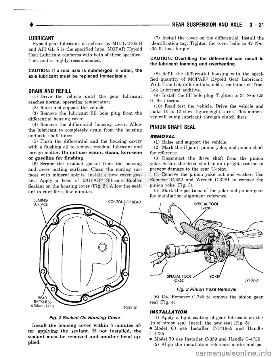
ket. Apply a bead of MOPAR® Silicone Rubber Sealant on the housing cover (Fig. 2). Allow the seal
ant to cure for a few minutes.
SEALING
SURFACE
CONTOUR
OF
BEAD
BEAD
THICKNESS
6.35mm
(1/4")
J9302-30
Fig.
2 Sealant On Housing Cower
Install
the
housing
cover
within 5
minutes
af
ter
applying
the
sealant.
If not
installed,
the
sealant
must be
removed
and another
bead
ap
plied.
(7) Install the cover on the differential. Install the
identification tag. Tighten the cover bolts to 47 Nem (35 ft. lbs.) torque.
CAUTION:
Overfilling
the differential" can
result
in
the
lubricant
foaming
and
overheating.
(8) Refill the differential housing with the speci
fied quantity of MOPAR® Hypoid Gear Lubricant.
With Trac-Lok differentials, add a container of Trac-
Lok Lubricant additive.
(9) Install the fill hole plug. Tighten to 34 N-m (25
ft. lbs.) torque.
(10) Road test the vehicle. Drive the vehicle and
make 10 to 12 slow, figure-eight turns. This maneu
ver will pump lubricant through clutch discs.
PINION
SHAFT
SEAL
REMOVAL
(1) Raise and support the vehicle.
(2) Mark the U-joint, pinion yoke, and pinion shaft
for reference.
(3) Disconnect the drive shaft from the pinion
yoke. Secure the drive shaft in an upright position to
prevent damage to the rear U-joint.
(4) Remove the pinion yoke nut and washer. Use
Remover C-452 and Wrench C-3281 to remove the
pinion yoke (Fig. 3).
(5) Mark the positions of the yoke and pinion gear
for installation alignment reference.
SPECIAL
TOOL
C-3281
SPECIAL
TOOL
C-452
J9102-31
Fig.
3 Pinion Yoke
Removal
(6) Use Remover C-748 to remove the pinion gear
seal (Fig. 4).
INSTALLATION
(1) Apply a light coating of gear lubricant on the
lip of pinion seal. Install the new seal (Fig. 5);
• Model 60 use Installer C-3719-A and Handle C-4735
• Model 70 use Installer C-359 and Handle C-4735 (2) Align the installation reference marks and po-
Page 191 of 1502
5
- 4
BRAKES
• (3) During road test, make normal and firm brake
stops in 25-40 mph (40-64 Km/h) range. Note faulty
brake operation such as pull, grab, drag, noise, low
pedal, etc.
(4) Inspect suspect brake components and refer to
problem diagnosis information for causes of various
brake conditions.
COMPONENT
INSPECTION
Fluid leak points and dragging brake units can usu
ally be located without removing any components. The
area around a leak point will be wet with fluid. The
components at a dragging brake unit (wheel, tire, rotor)
will be quite warm or hot to the touch.
Other brake problem conditions will require compo
nent removal for proper inspection. Raise the vehicle and remove the necessary wheels for better visual ac
cess.
DIAGNOSING BRAKE
PROBLEMS
PEDAL FALLS
AWAY
A
brake pedal that falls away under steady foot
pressure is the result of a system leak. The leak
point could be at a brakeline, fitting, hose, or caliper. Internal leakage in the master cylinder caused by
worn or damaged piston cups, may also be the prob lem cause.
If leakage is severe, fluid will be evident at or around
the leaking component. However, internal leakage in
the master cylinder may not be physically evident. Re fer to the cylinder test procedure in this section.
LOW PEDAL
If a low pedal is experienced, pump the pedal sev
eral times. If the pedal comes back up, worn lining
and worn rotors or drums are the likely causes.
A decrease in fluid level in the master cylinder res
ervoirs may only be the result of normal lining wear.
Fluid level can be expected to decrease in proportion to wear. It is a result of the outward movement of
caliper and wheel cylinder pistons to compensate for
normal wear. Top off the reservoir fluid level and
check brake operation to verify proper brake action.
SPONGY PEDAL. A spongy pedal is most often caused by air in the sys
tem. Thin brake drums or substandard brake lines and
hoses can also cause a spongy pedal. The proper course
of action is to bleed the system and replace thin drums and suspect quality brake lines and hoses.
HARD PEDAL
OR
HIGH
PEDAL
EFFORT
A hard pedal or high pedal effort may be due to
lining that is water soaked, contaminated, glazed, or
badly worn. The power booster or check valve could also be faulty. On diesel engine models, high pedal effort may be
the result of a low vacuum condition. If the booster and check valve are OK, the problem may be related
to a vacuum pump hose, hose connection, hose fit
ting, pump diaphragm, or drive gear. Vacuum pump output can be checked with a standard vacuum
gauge. Vacuum output should range from 8.5 to 25 inches vacuum. If vacuum pump output is within
limits,
check the power booster and check valve as
described in this section.
BRAKE DRAG
Brake drag occurs when the lining is in constant
contact with the rotor or drum. Drag can occur at
one wheel, all wheels, fronts only, or rears only. It is a product of incomplete brakeshoe release. Drag can
be minor or severe enough to overheat the linings,
rotors and drums.
Brake drag can also effect fuel economy. If undetec
ted, minor brake drag can be misdiagnosed as an en gine or transmission/torque converter problem.
Minor drag will usually cause slight surface charring
of the lining. It can also generate hard spots in rotors and drums from the overheat-cool down process. In most
cases,
the rotors, drums, wheels and tires are quite
warm to the touch after the vehicle is stopped.
Severe drag can char the brake lining all the way
through. It can also distort and score rotors and drums to the point of replacement. The wheels, tires and brake components will be extremely hot. In se
vere cases, the lining may generate smoke as it chars
from overheating.
Some common causes of brake drag are:
• seized or improperly adjusted parking brake cables
• loose/worn wheel bearing
• seized caliper or wheel cylinder piston
• caliper binding on corroded bushings or rusted
slide surfaces
• loose caliper mounting bracket
• drum brakeshoes binding on worn or damaged sup
port plates
• misassembled components. If brake drag occurs at all wheels, the problem may
be related to a blocked master cylinder return port, or faulty power booster that binds and does not release.
BRAKE FADE
Brake fade is a product of overheating caused by
brake drag. However, brake overheating and subse quent fade can also be caused by riding the brake
pedal, making repeated high deceleration stops in a short time span, or constant braking on steep moun
tain roads. Refer to the Brake Drag information in
this section for additional causes.
PEDAL
PULSA
TION
Pedal pulsation is caused by components that are
loose, out of round, or worn beyond tolerance limits.
Page 192 of 1502

•
BRAKES
5 - 5 Disc brake rotors with excessive lateral runout or
thickness variation, or out of round brake drums are
the primary causes of pulsation. Other causes are loose
wheel bearings or calipers and worn, damaged tires.
PULL A
front pull condition could be the result of con
taminated lining in one caliper, seized caliper piston,
binding caliper, loose caliper, loose or corroded slide
pins,
improper brakeshoes, or a damaged rotor.
A worn, damaged wheel bearing or suspension compo
nent are further causes of pull. A damaged front tire (bruised, ply separation) can also cause pull.
A common and frequently misdiagnosed pull condi
tion is where direction of pull changes after a few
stops.
The cause is a combination of brake drag fol
lowed by fade at one of the brake units.
As the dragging brake overheats, efficiency is so
reduced that fade occurs. Since the opposite brake
unit is still functioning normally, its braking effect is
magnified. This causes pull to switch direction in fa
vor of the normally functioning brake unit.
When diagnosing a change in pull condition, re
member that pull will return to the original direction
if the dragging brake unit is allowed to cool down (and is not seriously damaged).
REAR BRAKE GRAB
OR
PULL
Rear grab or pull is usually caused by an improperly
adjusted or seized parking brake cable, contaminated
lining, bent or binding shoes and support plates, or im
properly assembled components. This is particularly
true when only one rear wheel is involved. However,
when both rear wheels are affected, the master cylinder or proportioning valve could be at fault.
BRAKES
DO NOT
HOLD
AFTER
DRIVING
THROUGH
DEEP
WATER
PUDDLES
This condition is generally caused by water soaked
lining. If the lining is only wet, it can be dried by driv
ing with the brakes very lightly applied for a few min
utes.
However, if the lining is thoroughly wet and dirty,
disassembly and cleaning will be necessary.
BRAKE NOISE
Squeak/Squeal
Brake squeak or squeal may be due to linings that
are wet or contaminated with brake fluid, grease, or oil. Glazed linings and rotors with hard spots can also con
tribute to squeak. Dirt and foreign material embedded in the brake lining can also cause squeak/squeal.
A very loud squeak or squeal is frequently a sign of
severely worn brake lining. If the lining has worn
through to the brakeshoes in spots, metal-to-metal con
tact occurs. If the condition is allowed to continue, ro tors can become so scored that replacement is necessary.
Thump/Clunk
Thumping or clunk noises during braking are fre
quently not caused by brake components. In many
cases,
such noises are caused by loose or damaged steering, suspension, or engine components. How
ever, calipers that bind on the slide pins, or slide sur
faces,
can generate a thump or clunk noise. Worn
out, improperly adjusted, or improperly assembled
rear brakeshoes can also produce a thump noise.
Chatter
Brake chatter is usually caused by loose or worn
components, or glazed/burnt lining. Rotors with hard
spots can also contribute to chatter. Additional
causes of chatter are out of tolerance rotors, brake
lining not securely attached to the shoes, loose wheel
bearings and contaminated brake lining.
Brakelining Contamination Brakelining contamination is usually a product of
leaking calipers or wheel cylinders, driving through
deep water puddles, or lining that has become cov
ered with grease and grit during repair.
Wheel and
Tire
Problems Some conditions attributed to brake components
may actually be caused by a wheel or tire problem.
A damaged wheel can cause shudder, vibration and
pull. A worn or damaged tire can also cause pull.
Severely worn tires with very little tread left can
produce a grab-like condition as the tire loses and re covers traction. Flat-spotted tires can cause vibration and wheel
tramp and generate shudder during brake operation. A tire with internal damage such as a severe
bruise or ply separation can cause pull and vibration.
MASTER
CYLINDER/POWER BOOSTER TEST
(1) Start engine and check booster vacuum hose
connections. Hissing noise indicates a vacuum leak. Correct any leaks before proceeding. (2) Stop engine and shift transmission into Neu
tral (3) Pump brake pedal until all vacuum reserve in
booster is depleted. (4) Press and hold brake pedal under light foot
pressure. (a) If pedal holds firm, proceed to step (5).
(b) If pedal does not hold firm and falls away,
master cylinder is faulty (internal leakage). (5) Start engine and note pedal action. (a) If pedal falls away slightly under light foot
pressure then holds firm, proceed to step (6). (b) If pedal is effort is high, or no pedal action is
discernible, power booster or vacuum check valve is
faulty. Install known good check valve and repeat steps (2) through (5).
Page 272 of 1502
COOLING SYSTEM
CONTENTS page
DIAGNOSIS
... 4
ENGINE
ACCESSORY
DRIVE BELTS
40
ENGINE
BLOCK HEATERS
48
GENERAL
INFORMATION
Throughout this group, references are made to partic
ular vehicle models by alphabetical designation or by
the particular vehicle nameplate. A chart showing a
breakdown of alphabetical designations is included in
the Introduction section at the beginning of this man
ual.
5.9L gas powered engines will be' referred to as ei
ther: LDC (Light Duty Cycle) or HDC (Heavy Duty
Cycle).
COOLING
SYSTEM
The cooling system regulates engine operating tem
perature. It allows the engine to reach normal oper-
page
SERVICE
PROCEDURES
15
SPECIFICATIONS
; 49
ating temperature as quickly as possible. It also
maintains normal operating temperature and pre
vents overheating.
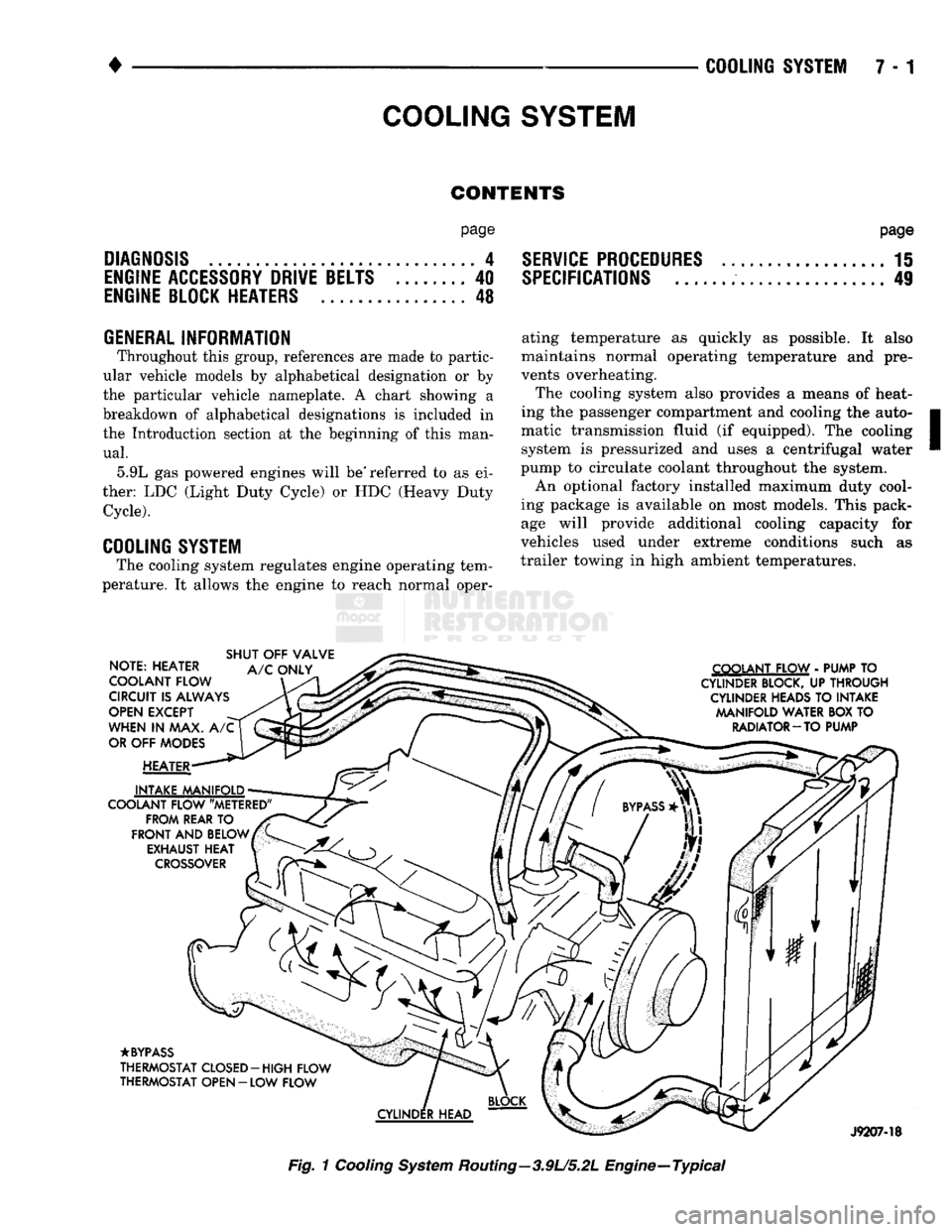
The cooling system also provides a means of heat
ing the passenger compartment and cooling the auto
matic transmission fluid (if equipped). The cooling system is pressurized and uses a centrifugal water
pump to circulate coolant throughout the system.
An optional factory installed maximum duty cool
ing package is available on most models. This pack age will provide additional cooling capacity for
vehicles used under extreme conditions such as
trailer towing in high ambient temperatures.
NOTE: HEATER
COOLANT FLOW
CIRCUIT
IS
ALWAYS
OPEN
EXCEPT
WHEN
IN MAX. A/C
OR
OFF
MODES
HEATER
INTAKE MANIFOLD
COOLANT FLOW "METERED" FROM REAR
TO
FRONT
AND
BELOW EXHAUST
HEAT
CROSSOVER
SHUT
OFF
VALVE
A/C
ONLY COOLANT FLOW
-
PUMP
TO
CYLINDER BLOCK,
UP
THROUGH CYLINDER HEADS
TO
INTAKE MANIFOLD WATER
BOX TO
RADIATOR-TO PUMP
•BYPASS
THERMOSTAT CLOSED-HIGH FLOW
THERMOSTAT OPEN
- LOW
FLOW
J9207-18
Fig.
1
Cooling
System
Routing—3.9U5.2L Engine—Typical
Page 273 of 1502
7 - 2
COOLING
SYSTEM
•
NOTE: HEATER
COOLANT FLOW
CIRCUIT
IS
ALWAYS
OPEN
EXCEPT
WHEN
IN MAX. A/C
OR
OFF
MODES
HEATER
INTAKE MANIFOLD
COOLANT FLOW "METERED" FROM REAR
TO
FRONT
AND
BELOW EXHAUST HEAT
CROSSOVER
SHUT
OFF
VALVE
A/C
ONLY COOLANT FLOW
-
PUMP
TO
CYLINDER
BLOCK,
UP
THROUGH
CYLINDER
HEADS
TO
INTAKE MANIFOLD WATER BOX
TO
RADIATOR
—
TO PUMP
•BYPASS
THERMOSTAT CLOSED-HIGH FLOW
THERMOSTAT OPEN
-
LOW FLOW
CYLINDER
HEAD
RR07B52
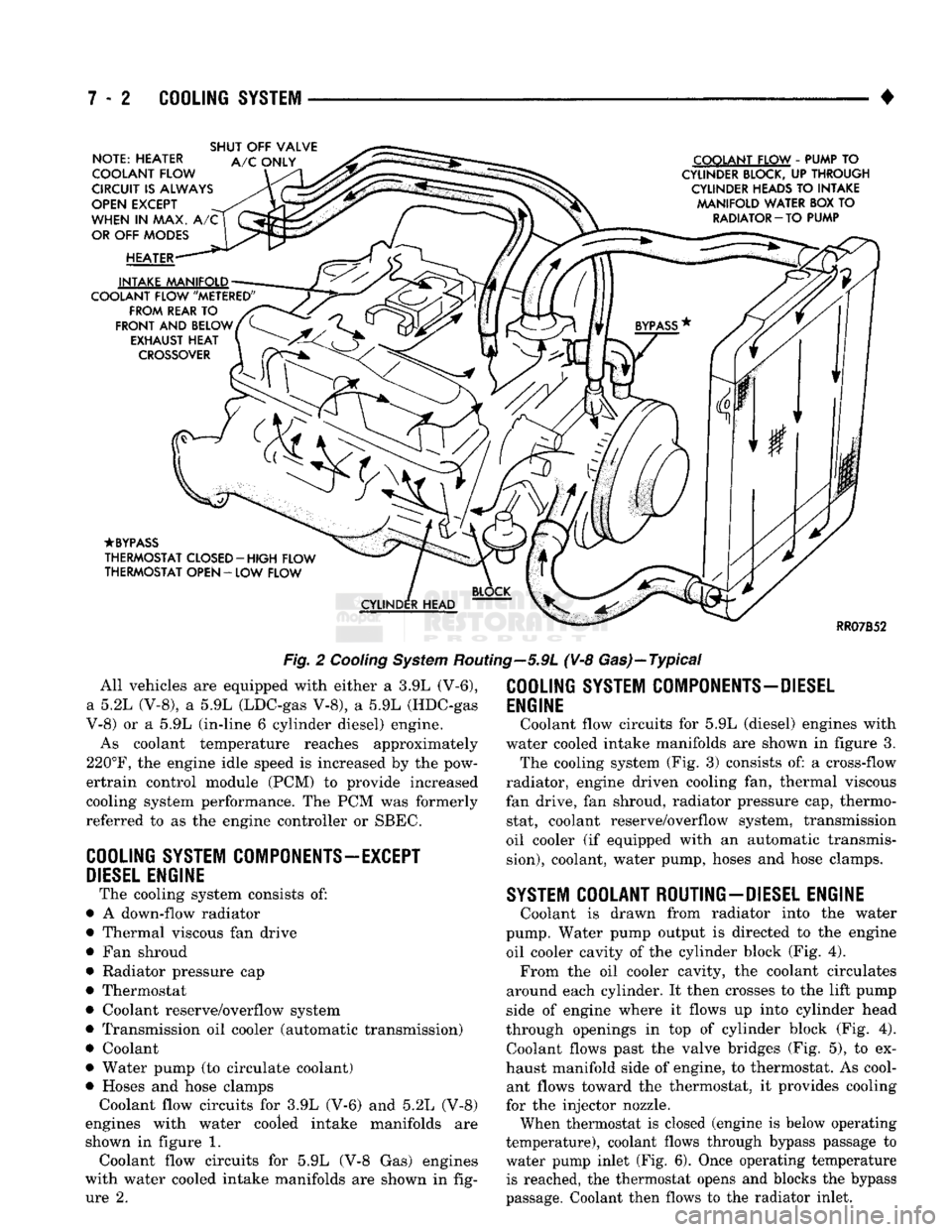
Fig.
2
Cooling
System
Routing—5.9L (V-8 Gas)—Typical All vehicles are equipped with either a 3.9L (V-6),
a 5.2L (V-8), a 5.9L (LDC-gas V-8), a 5.9L (HDC-gas
V-8) or a 5.9L (in-line 6 cylinder diesel) engine.
As coolant temperature reaches approximately
220°F,
the engine idle speed is increased by the pow-
ertrain control module (PCM) to provide increased
cooling system performance. The PCM was formerly
referred to as the engine controller or SBEC.
COOLING
SYSTEM
COMPONENTS—EXCEPT
DIESEL
ENGINE
The cooling system consists of:
• A down-flow radiator
• Thermal viscous fan drive
• Fan shroud
• Radiator pressure cap
• Thermostat
• Coolant reserve/overflow system
• Transmission oil cooler (automatic transmission)
• Coolant
• Water pump (to circulate coolant)
• Hoses and hose clamps Coolant flow circuits for 3.9L (V-6) and 5.2L (V-8)
engines with water cooled intake manifolds are
shown in figure 1. Coolant flow circuits for 5.9L (V-8 Gas) engines
with water cooled intake manifolds are shown in fig ure 2.
COOLING
SYSTEM
COMPONENTS-DIESEL
ENGINE
Coolant flow circuits for 5.9L (diesel) engines with
water cooled intake manifolds are shown in figure 3. The cooling system (Fig. 3) consists of: a cross-flow
radiator, engine driven cooling fan, thermal viscous
fan drive, fan shroud, radiator pressure cap, thermo stat, coolant reserve/overflow system, transmission
oil cooler (if equipped with an automatic transmis
sion),
coolant, water pump, hoses and hose clamps.
SYSTEM
COOLANT ROUTING-DIESEL ENGINE
Coolant is drawn from radiator into the water
pump. Water pump output is directed to the engine oil cooler cavity of the cylinder block (Fig. 4). From the oil cooler cavity, the coolant circulates
around each cylinder. It then crosses to the lift pump
side of engine where it flows up into cylinder head
through openings in top of cylinder block (Fig. 4). Coolant flows past the valve bridges (Fig. 5), to ex
haust manifold side of engine, to thermostat. As cool ant flows toward the thermostat, it provides cooling
for the injector nozzle.
When thermostat is closed (engine is below operating
temperature), coolant flows through bypass passage to
water pump inlet (Fig. 6). Once operating temperature is reached, the thermostat opens and blocks the bypass
passage. Coolant then flows to the radiator inlet.
Page 275 of 1502
DIAGNOSIS
PRELIMINARY
CHECKS
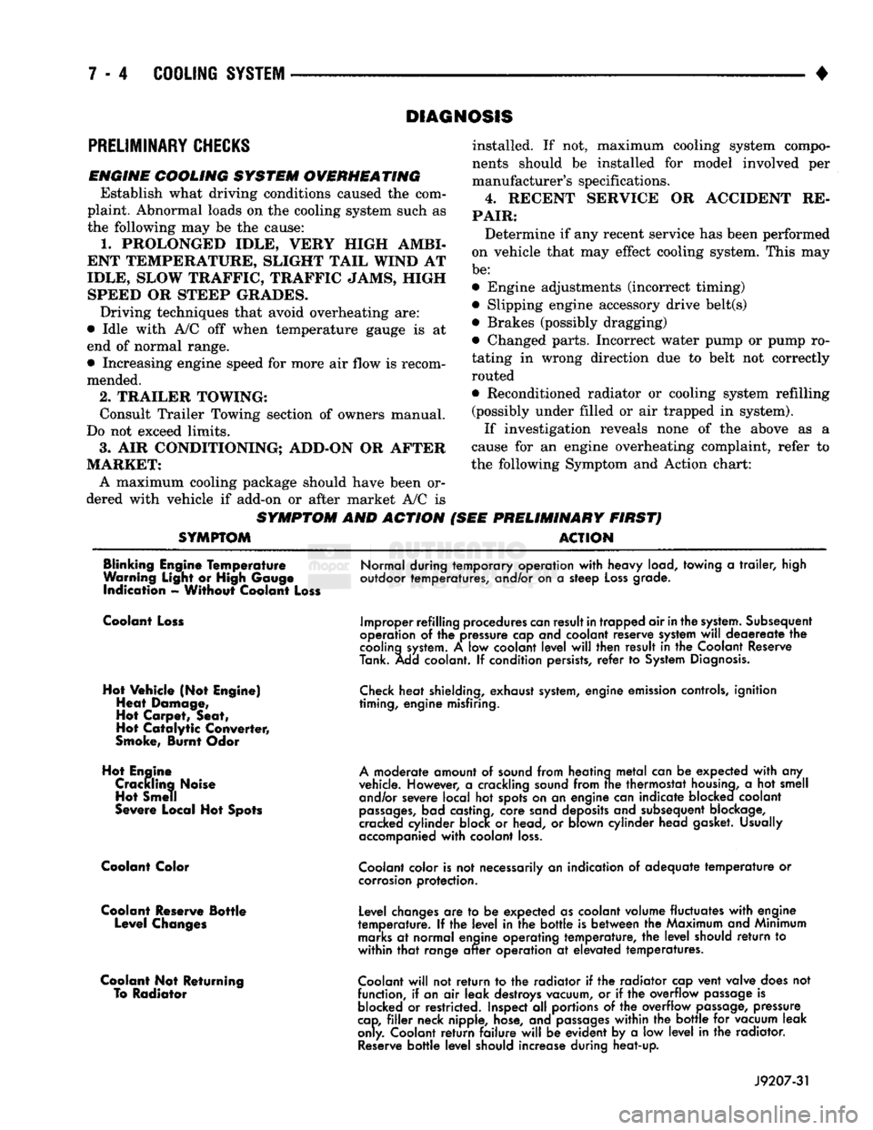
ENGINE COOLING SYSTEM OVERHEATING Establish what driving conditions caused the com
plaint. Abnormal loads on the cooling system such as
the following may be the cause:
1.
PROLONGED IDLE, VERY HIGH AMBI
ENT TEMPERATURE, SLIGHT TAIL WIND AT
IDLE, SLOW TRAFFIC, TRAFFIC JAMS, HIGH SPEED OR STEEP GRADES.
Driving techniques that avoid overheating are:
• Idle with A/C off when temperature gauge is at
end of normal range. * Increasing engine speed for more air flow is recom
mended.
2.
TRAILER TOWING: Consult Trailer Towing section of owners manual.
Do not exceed limits.
3.
AIR CONDITIONING; ADD-ON OR AFTER
MARKET: A maximum cooling package should have been or
dered with vehicle if add-on or after market A/C is
SYMPTOM AND ACTION
SYMPTOM
installed. If not, maximum cooling system compo
nents should be installed for model involved per
manufacturer's specifications.
4.
RECENT SERVICE OR ACCIDENT RE
PAIR:
Determine if any recent service has been performed
on vehicle that may effect cooling system. This may
be:
• Engine adjustments (incorrect timing)
• Slipping engine accessory drive belt(s) • Brakes (possibly dragging)
• Changed parts. Incorrect water pump or pump ro
tating in wrong direction due to belt not correctly
routed
• Reconditioned radiator or cooling system refilling (possibly under filled or air trapped in system).
If investigation reveals none of the above as a
cause for an engine overheating complaint, refer to
the following Symptom and Action chart:
PRELIMINARY FIRST) ACTION
Blinking Engine Temperature
Warning Light or High Gauge indication - Without Coolant Loss
Normal during temporary operation
with
heavy load, towing
a
trailer,
high
outdoor temperatures, and/or on
a
steep
Loss
grade.
Coolant Loss
Hot Vehicle (Not Engine) Heat Damage,
Hot Carpet, Seat,
Hot
Catalytic
Converter,
Smoke, Burnt Odor
Hot Engine Crackling Noise Hot Smell
Severe Local Hot Spots
Coolant Color
Coolant Reserve Bottle Level Changes
Coolant Not Returning To Radiator
Improper refilling procedures
can
result
in
trapped air
in
the
system.
Subsequent
operation
of the
pressure cap and coolant reserve system
will
deaereate
the
cooling
system.
A low
coolant
level
will
then result
in the
Coolant Reserve
Tank. Add coolant.
If
condition persists,
refer
to
System
Diagnosis.
Check
heat shielding, exhaust
system,
engine emission controls, ignition
timing, engine misfiring.
A
moderate amount
of
sound from heating
metal
can
be
expected
with
any
vehicle. However,
a
crackling sound from
trie
thermostat
housing,
a hot
smell and/or severe local
hot
spots on
an
engine can indicate blocked coolant
passages,
bad castina, core sand deposits and subsequent blockage,
cracked cylinder block
or
head,
or
blown cylinder head gasket. Usually
accompanied
with
coolant
loss.
Coolant
color is
not
necessarily
an
indication
of
adequate
temperature
or
corrosion
protection.
Level changes
are to be
expected as coolant volume fluctuates
with
engine
temperature.
If the
level
in the
bottle
is
between
the
Maximum and Minimum
marks
at
normal engine operating temperature,
the
level
should
return
to
within
that
range
after
operation
at
elevated temperatures.
Coolant
will
not
return
to the
radiator
if the
radiator cap vent valve does
not
function,
if
an
air
leak destroys vacuum,
or if the
overflow
passage
is
blocked
or
restricted. Inspect
all
portions
of the
overflow
passage,
pressure
cap,
filler
neck nipple, hose, and
passages
within
the
bottle
for
vacuum leak
only. Coolant
return
failure
will
be
evident
by a low
level
in the
radiator.
Reserve
bottle
level
should increase during heat-up.
J9207-31