1993 DODGE TRUCK Rear axle nut
[x] Cancel search: Rear axle nutPage 49 of 1502
0 - 30
LUBRICATION
AND
MAINTENANCE
— - •
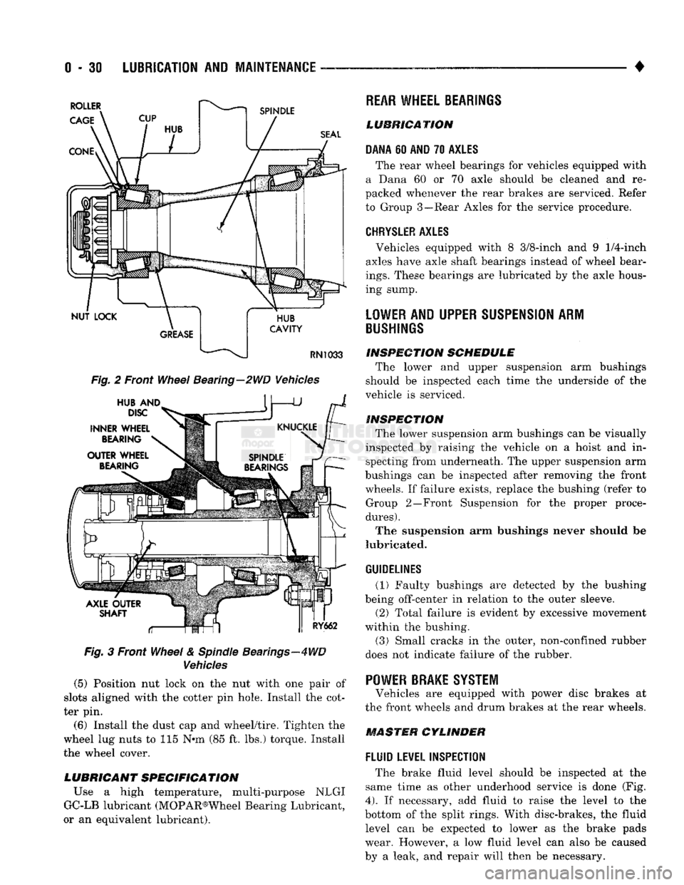
Fig.
2 Front
Wheel
Bearing—2WD Vehicles
Fig.
3 Front
Wheel
&
Spindle
Bearings—4WD
Vehicles
(5) Position nut lock on the nut with one pair of
slots aligned with the cotter pin hole. Install the cot
ter pin.
(6) Install the dust cap and wheel/tire. Tighten the
wheel lug nuts to 115 N*m (85 ft. lbs.) torque. Install
the wheel cover.
LUBRICANT SPECIFICATION
Use a high temperature, multi-purpose NLGI
GC-LB lubricant (MOPAR®Wheel Bearing Lubricant,
or an equivalent lubricant).
REAR
WHEEL BEARINGS
LUBRICATION
DANA
60
AND
70
AXLES
The rear wheel bearings for vehicles equipped with
a Dana 60 or 70 axle should be cleaned and re
packed whenever the rear brakes are serviced. Refer
to Group 3—Rear Axles for the service procedure.
CHRYSLER
AXLES
, Vehicles equipped with 8 3/8-inch and 9
1/4-inch
axles have axle shaft bearings instead of wheel bear
ings.
These bearings are lubricated by the axle hous
ing sump.
LOWER
AND UPPER
SUSPENSION
ARM
BUSHINGS
INSPECTION
SCHEDULE
The lower and upper suspension arm bushings
should be inspected each time the underside of the
vehicle is serviced.
INSPECTION
The lower suspension arm bushings can be visually
inspected by raising the vehicle on a hoist and in specting from underneath. The upper suspension arm
bushings can be inspected after removing the front wheels. If failure exists, replace the bushing (refer to Group 2—Front Suspension for the proper proce
dures).
The suspension arm bushings never should be
lubricated.
GUIDELINES
(1) Faulty bushings are detected by the bushing
being off-center in relation to the outer sleeve.
(2) Total failure is evident by excessive movement
within the bushing.
(3)
Small cracks in the outer, non-confined rubber
does not indicate failure of the rubber. '
POWER BRAKE SYSTEM
Vehicles are equipped with power disc brakes at
the front wheels and drum brakes at the rear wheels.
MASTER CYLINDER
FLUID
LEVEL INSPECTION
The brake fluid level should be inspected at the
same time as other underhood service is done (Fig.
4).
If necessary, add fluid to raise the level to the
bottom of the split rings. With disc-brakes, the fluid level can be expected to lower as the brake pads
wear. However, a low fluid level can also be caused
by a leak, and repair will then be necessary.
Page 61 of 1502
2
- 8
FRONT SUSPENSION
AND
AXLE
• INSTALLATION
(1) If a bearing and cup must be replaced, remove
the cup from the wheel hub/rotor bore (Fig. 1). Use a
brass drift or an appropriate removal tool to tap out
the cup.
(2) Install the replacement bearing cup(s) with an
appropriate installation tool. (3) Apply lubricant to surface area of the wheel
hub/rotor bore. Install the inner wheel bearing in the
hub/rotor. Install a replacement bearing seal with an appropriate seal installation tool. (4) Inspect the bearing and seal contact surfaces on
the steering knuckle spindle for burrs and/or rough ness (Fig. 1).
(5) Remove all the rough contact surfaces from the
spindle. Apply a coating of multi-purpose NLGI,
grade 2, EP-type lubricant to the spindle surface.
CAUTION: Us© care to prevent the inner
wheel
bear
ing
and bearing
seal
from contacting the steering
knuckle
spindle
threads during removal (Fig. 1).
Otherwise,
the threads, bearing, and
seal
could
be
damaged.
(6) Carefully slide the wheel hub/rotor onto the
spindle.
Install the outer wheel bearing, the washer and
nut.
(7) Tighten the nut to 41 to 54 Nnn (30 to 40 ft.
lbs.) torque while rotating the wheel hub/rotor. Stop
the hub/rotor and loosen the nut to completely re
lease the bearing preload torque. Next, tighten the
nut finger-tight, install the nut lock. Install a re
placement cotter pin.
(8) The wheel bearing adjustment (above) should
have 0.001 to 0.003 inch (0.254 to 0.0762 mm) end
play.
(9) Clean the dust cap. Apply a coating of multi
purpose NLGI, grade 2, EP-type lubricant to internal surface. Install the cap. Do not fill the dust cap with lubricant. (10) Install the brake caliper, refer to Group 5,
Brakes. (11) Install the wheel and tire, refer to Wheel and
Tire Installation in this section. Lower the vehicle.
LOWER SUSPENSION ARM STRUT
REMOVAL (1) Raise and support the vehicle.
(2) Use a small drift and a hammer to drive the
spring pin from the front of the strut. Remove the
spring pin, nut, retainer and bushing from the end of
the strut (Fig. 2).
(3) Remove the strut rear bolts and jounce bumper
from the bracket. Remove the strut from the vehicle (Fig. 2).
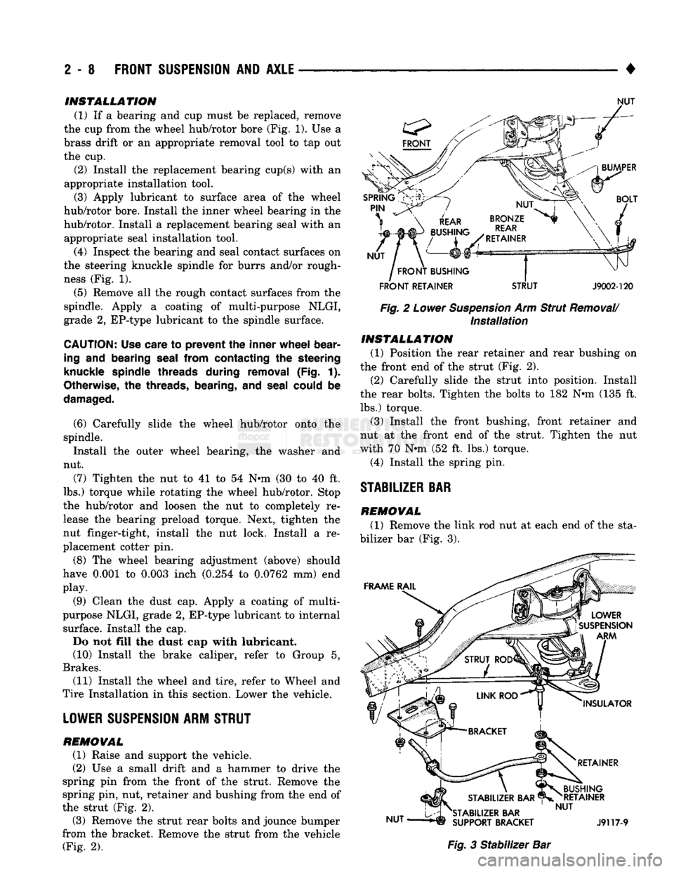
NUT
FRONT
RETAINER
STRUT
J9002-120
Fig. 2 Lower Suspension Arm Strut Removal/ Installation INSTALLATION
(1) Position the rear retainer and rear bushing on
the front end of the strut (Fig. 2).
(2) Carefully slide the strut into position. Install
the rear bolts. Tighten the bolts to 182 Nnn (135 ft. lbs.) torque.
(3) Install the front bushing, front retainer and
nut at the front end of the strut. Tighten the nut
with 70 Nnn (52 ft. lbs.) torque.
(4) Install the spring pin.
STABILIZER
BAR
REMOVAL
(1) Remove the link rod nut at each end of the sta
bilizer bar (Fig. 3). Fig. 3 Stabilizer Bar
Page 68 of 1502
•
FRONT
SUSPENSION
AND
AXLE
2 - 15 Ensure the shock absorber is positioned on the
stud with retainers correctly located (Fig. 2).
(2)
Position the inner retainers on the mounting
studs.
(3) Install the shock on the upper and lower stud
and install the outer retainers.
(4) Install the nuts on the frame bracket and axle
(Fig. 2). (5) Tighten the shock absorber upper and lower
nuts;
• Standard shock upper and lower nut to 75 Nnn (55
ft. lbs.) torque
• Air-adjustable shock upper nut to 75 N»m (55 ft. lbs.) torque, lower nut to 271 Nnn (200 ft. lbs.)
torque
CAUTION:
Vehicles
with
air
shocks MUST
maintain
a
minimum
pressure
of 10 to 15 psi (70 to 105 kPa). Operation below the specified minimum
pressures
may cause damage.
(6) Remove the supports and lower the vehicle.
LEAF
SPRINGS
REMOVAL
(1) Raise and support the frame until all weight is
removed from the front springs. (2) With the front tires in contact with the surface,
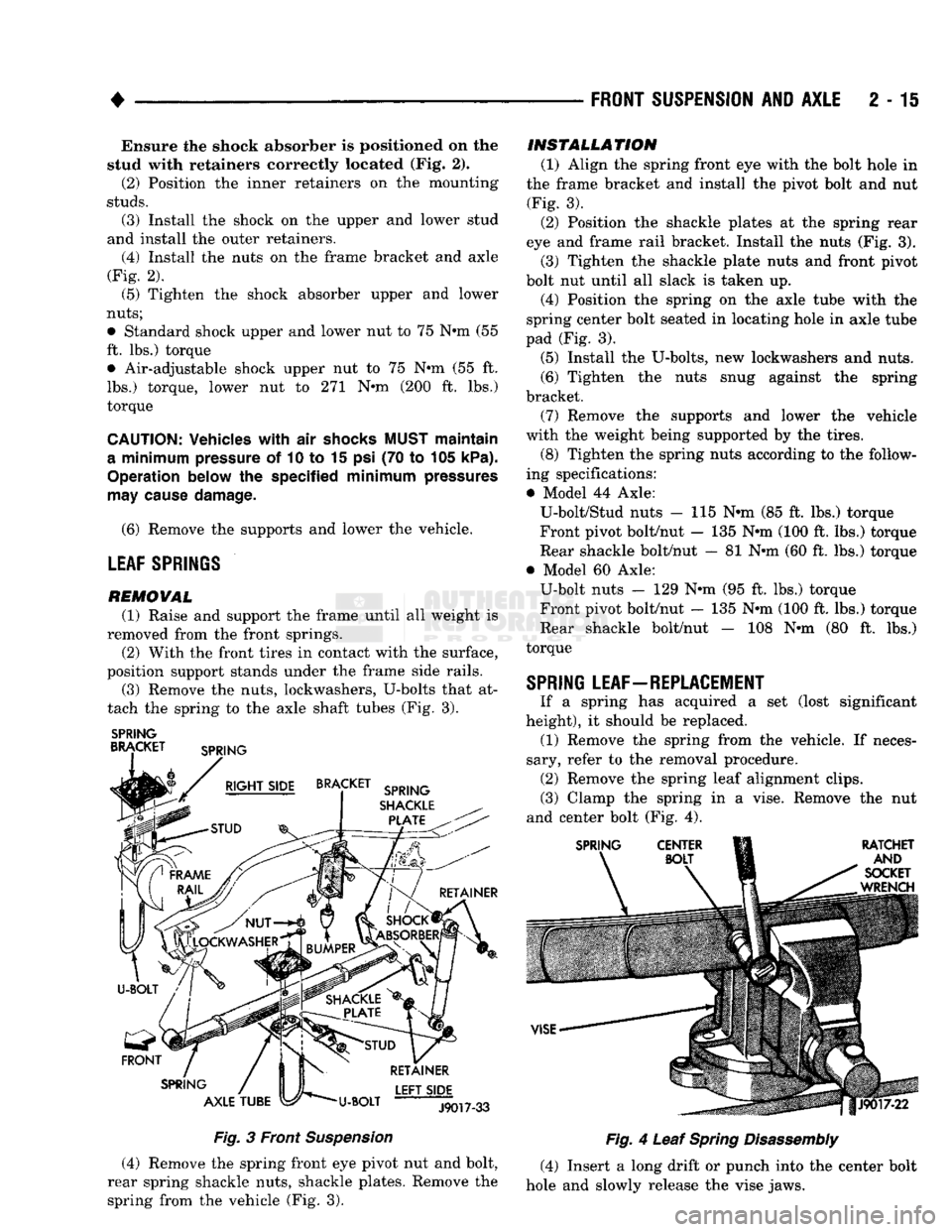
position support stands under the frame side rails. (3) Remove the nuts, lockwashers, U-bolts that at
tach the spring to the axle shaft tubes (Fig. 3).
SPRING
BRACKET SPRING
BRACKET SPRING
SHACKLE
PLATE
FRONT
SPRING
AXLE
TUBE U-BOLT LEFT
SIDE
J9017-33
Fig.
3 Front
Suspension
(4) Remove the spring front eye pivot nut and bolt,
rear spring shackle nuts, shackle plates. Remove the spring from the vehicle (Fig. 3).
INSTALLATION
(1) Align the spring front eye with the bolt hole in
the frame bracket and install the pivot bolt and nut (Fig. 3). (2) Position the shackle plates at the spring rear
eye and frame rail bracket. Install the nuts (Fig. 3). (3) Tighten the shackle plate nuts and front pivot
bolt nut until all slack is taken up. (4) Position the spring on the axle tube with the
spring center bolt seated in locating hole in axle tube
pad (Fig. 3).
(5) Install the U-bolts, new lockwashers and nuts.
(6) Tighten the nuts snug against the spring
bracket.
(7) Remove the supports and lower the vehicle
with the weight being supported by the tires. (8) Tighten the spring nuts according to the follow
ing specifications:
• Model 44 Axle: U-bolt/Stud nuts - 115 Nnn (85 ft. lbs.) torque
Front pivot bolt/nut — 135 Nnn (100 ft. lbs.) torque
Rear shackle bolt/nut — 81 Nnn (60 ft. lbs.) torque
• Model 60 Axle: U-bolt nuts - 129 Nnn (95 ft. lbs.) torque Front pivot bolt/nut - 135 Nnn (100 ft. lbs.) torque
Rear shackle bolt/nut - 108 Nnn (80 ft. lbs.)
torque
SPRING LEAF-REPLACEMENT
If a spring has acquired a set (lost significant
height), it should be replaced. (1) Remove the spring from the vehicle. If neces
sary, refer to the removal procedure. (2) Remove the spring leaf alignment clips.
(3) Clamp the spring in a vise. Remove the nut
and center bolt (Fig. 4).
SPRING
CENTER
RATCHET
AND
SOCKET
WRENCH
Fig.
4 Leaf
Spring
Disassembly
(4) Insert a long drift or punch into the center bolt
hole and slowly release the vise jaws.
Page 72 of 1502
FRONT
SUSPENSION
AND
AXLE
2 - 19
DRAIN
AND
REFILL
(1) Drive the vehicle until the gear lubricant
reaches normal operating temperature. (2) Raise and support the vehicle.
(3) Remove the lubricant fill hole plug from the
differential housing cover.
(4) Remove the differential housing cover. Allow
the original lubricant to completely drain from the
housing and axle shaft tubes.
(5) With standard differential, clean the differen
tial and the housing cavity with a flushing oil (or light engine oil). This will remove the residual lubricant and foreign matter. Do not use water, steam,
kerosene or gasoline for flushing. (6) Scrape the residual gasket from the housing
and cover mating surfaces. Clean the mating sur
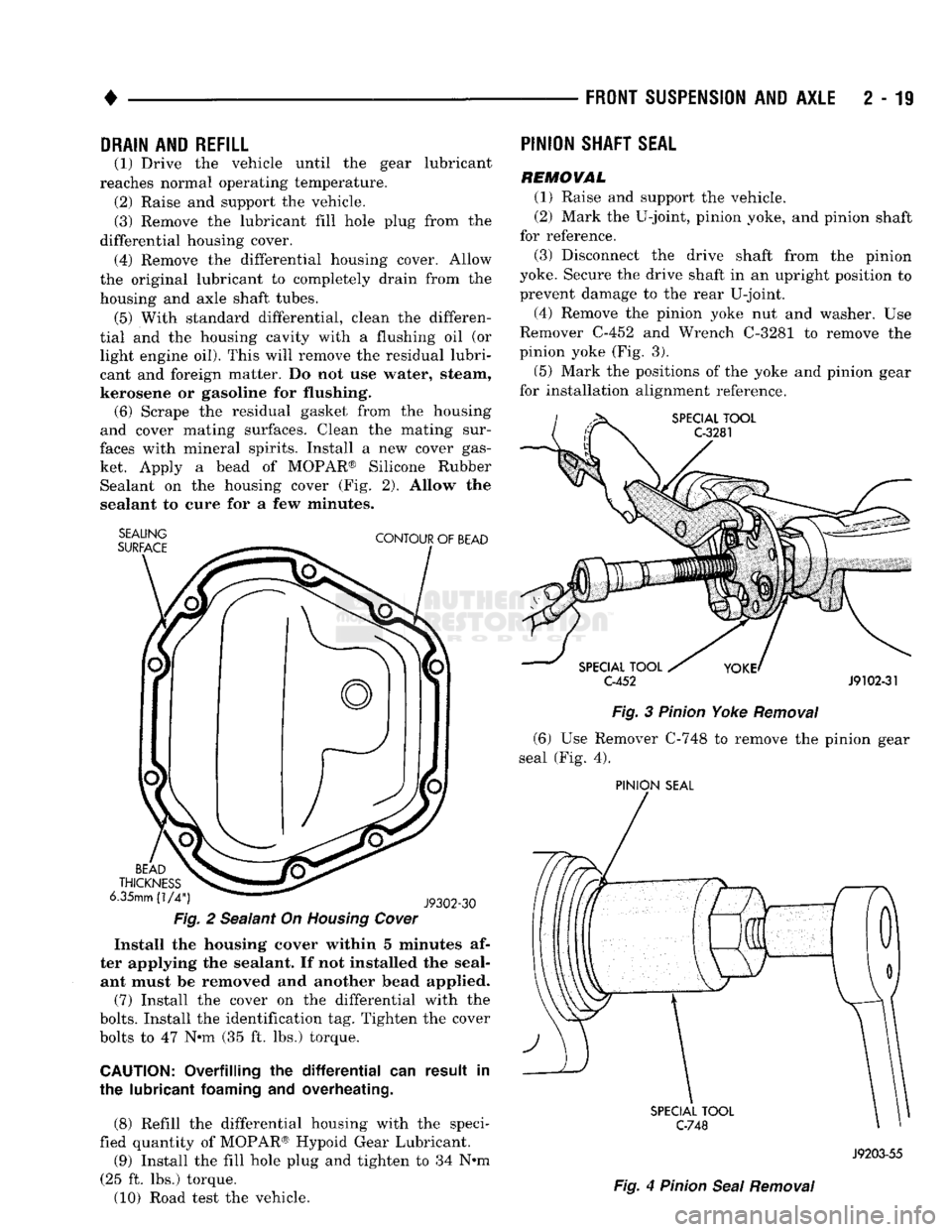
faces with mineral spirits. Install a new cover gas ket. Apply a bead of MOPAR® Silicone Rubber Sealant on the housing cover (Fig. 2). Allow the
sealant to cure for a few minutes.
SEALING
SURFACE
CONTOUR
OF
BEAD
BEAD
THICKNESS
6.35mm
(1/4")
J9302-30
Fig.
2 Sealant On
Housing
Cover
Install the housing cover within 5 minutes af
ter applying the sealant. If not installed the seal ant must be removed and another bead applied.
(7) Install the cover on the differential with the
bolts.
Install the identification tag. Tighten the cover
bolts to 47 Nnn (35 ft. lbs.) torque.
CAUTION:
Overfilling the
differential
can result in
the lubricant
foaming
and overheating.
(8) Refill the differential housing with the speci
fied quantity of MOPAR® Hypoid Gear Lubricant.
(9) Install the fill hole plug and tighten to 34 N#m
(25 ft. lbs.) torque.
(10) Road test the vehicle.
PINION
SHAFT
SEAL
REMOVAL
(1) Raise and support the vehicle.
(2) Mark the U-joint, pinion yoke, and pinion shaft
for reference.
(3) Disconnect the drive shaft from the pinion
yoke. Secure the drive shaft in an upright position to prevent damage to the rear U-joint.
(4) Remove the pinion yoke nut and washer. Use
Remover C-452 and Wrench C-3281 to remove the
pinion yoke (Fig. 3).
(5) Mark the positions of the yoke and pinion gear
for installation alignment reference.
SPECIAL
TOOL
C-3281
SPECIAL
TOOL
C-452
J9102-31
Fig.
3
Pinion
Yoke
Removal
(6) Use Remover C-748 to remove the pinion gear
seal (Fig. 4).
PINION
SEAL
SPECIAL
TOOL
C-748
Fig.
4
Pinion
Seal
Removal
J9203-55
Page 80 of 1502
NUT
LEFT
ENGINE
MOUNT
LEFT
ENGINE
MOUNT
NUT
ANDyv
WASHER
VIEW
IN DIRECTION
OF ARROW
W
TORQUE
LET. POUNDS NEWTON
METRES
FULLY SEATED
HAND TIGHTENED
55
IN.
6
15 FT. 20
CLIP
ALIGN
WHITE
TAPE
TO END OF CLIP
VIEW
IN DIRECTION
OF
ARROW Z
WITH
V-6
CLIP.
SHIFT
MOTOR
ROUTE HOSE
TO
REAR
OF
DISTRIBUTOR
VIEW
IN DIRECTION
OF ARROW
Z
VIEW
IN
DIRECTION OF ARROW X
J9102-61
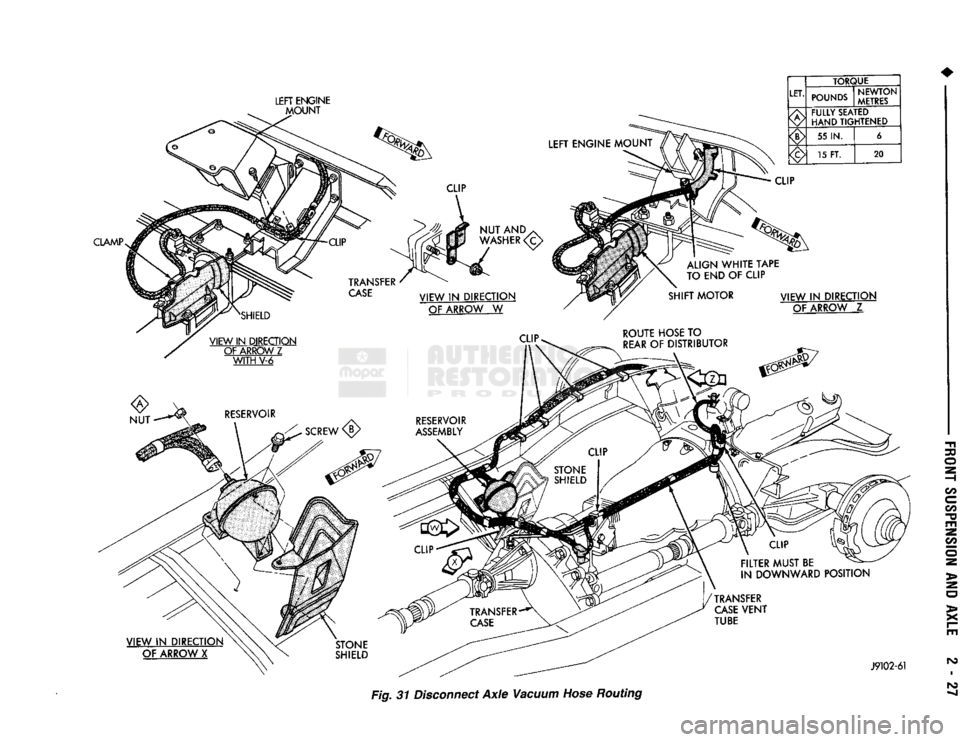
Fig. 31 Disconnect
Axle
Vacuum Hose Routing
Page 85 of 1502
2
- 32
FRONT
SUSPENSION
AND
AXLE
• (5) Disconnect flexible brake fluid hose fittings at
the frame crossmember. Plug the hoses at the fit
tings.
(6) Remove the shock absorber lower nut and stud
from the axle shaft tube bracket. Remove the nuts and disconnect the stabilizer bar links from the
spring brackets.
(7) Disconnect the vacuum hoses and wiring con
nections from the shift motor housing.
(8) Remove nuts and the washers from the spring
U-bolts. Remove the complete front axle from the ve
hicle.
INSTALLATION
(1) Position the front axle under the front of the
vehicle with the axle spring pads under the springs.
Place the spring brackets over the springs. Make sure the stabilizer bar link bolt holes face toward the
rear of the vehicle.
(2) Install the spring U-bolts, washers and nuts.
Refer to Front Suspension — 4WD Vehicles within
this group. (3) Install the shock absorber. Refer to Front Sus
pension — 4WD Vehicles within this group. (4) Connect the stabilizer bar links to the spring
brackets. Refer to Front Suspension-4WD Vehicles
within this group.
(5) Remove plugs and connect the brake hose fit
tings.
Refer to Group 5, Brakes. (6) Connect the drag-link ball stud to the steering
knuckle arm. Refer to Group 19, Steering. (7) Connect the drive shaft to the pinion yoke with
the installation reference marks aligned. Install the
washers and the nuts and tighten to 19 N*m (14 ft. lbs.) torque.
(8) Connect the vacuum hoses and wiring connec
tions to the shift motor housing. (9) Remove the supports, lower the vehicle and re
move the block from the brake pedal.
(10) Raise the vehicle.
• Bleed and adjust the brakes
• Lubricate all the ball stud fittings
• Inspect the differential housing lubricant level. Re
fer to Group 0, Lubrication and Maintenance. (11) Lower the vehicle and test the axle and sus
pension operation.
DIFFERENTIAL
DISASSEMBLY
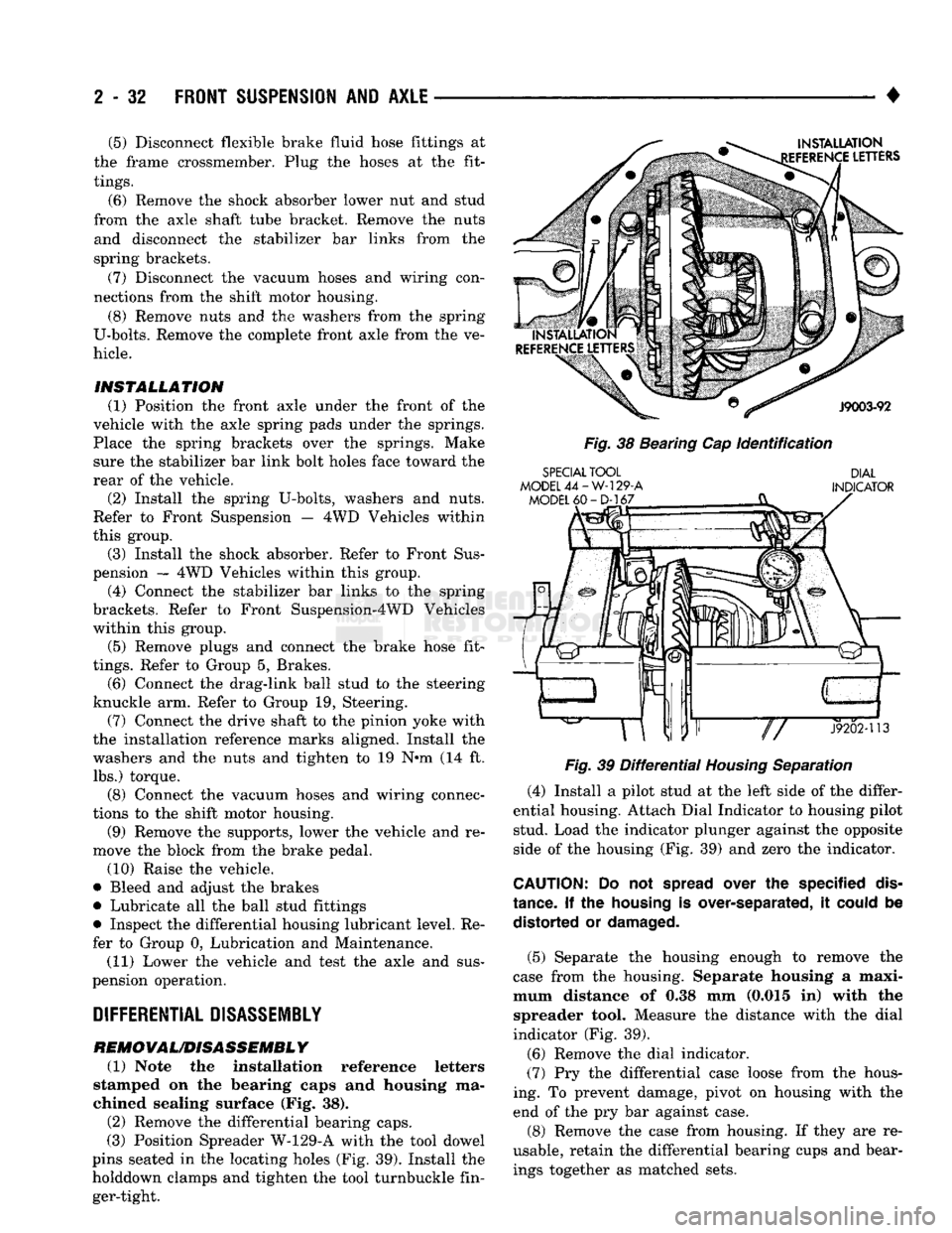
REMOVAL/DISASSEMBLY (1) Note the installation reference letters
stamped on the bearing caps and housing ma
chined sealing surface (Fig. 38). (2) Remove the differential bearing caps.
(3) Position Spreader W-129-A with the tool dowel
pins seated in the locating holes (Fig. 39). Install the
holddown clamps and tighten the tool turnbuckle fin ger-tight.
INSTALLATION
EFERENCE
LETTERS
J9003-92
Fig.
38 Bearing Cap
Identification
SPECIAL
TOOL
MODEL
44-W-129-A
MODEL
60-D-167
DIAL
INDICATOR
«ar"P—
J9202-113
Fig.
39
Differential
Housing
Separation
(4) Install a pilot stud at the left side of the differ
ential housing. Attach Dial Indicator to housing pilot stud. Load the indicator plunger against the opposite
side of the housing (Fig. 39) and zero the indicator.
CAUTION:
Do not
spread
over the specified
dis
tance.
If the
housing
is over-separated, it
could
be distorted or
damaged.
(5) Separate the housing enough to remove the
case from the housing. Separate housing a maxi
mum distance of 0.38 mm (0.015 in) with the spreader tool. Measure the distance with the dial
indicator (Fig. 39).
(6) Remove the dial indicator.
(7) Pry the differential case loose from the hous
ing. To prevent damage, pivot on housing with the end of the pry bar against case.
(8) Remove the case from housing. If they are re
usable, retain the differential bearing cups and bear ings together as matched sets.
Page 86 of 1502
•
FRONT
SUSPENSION
AND
AXLE
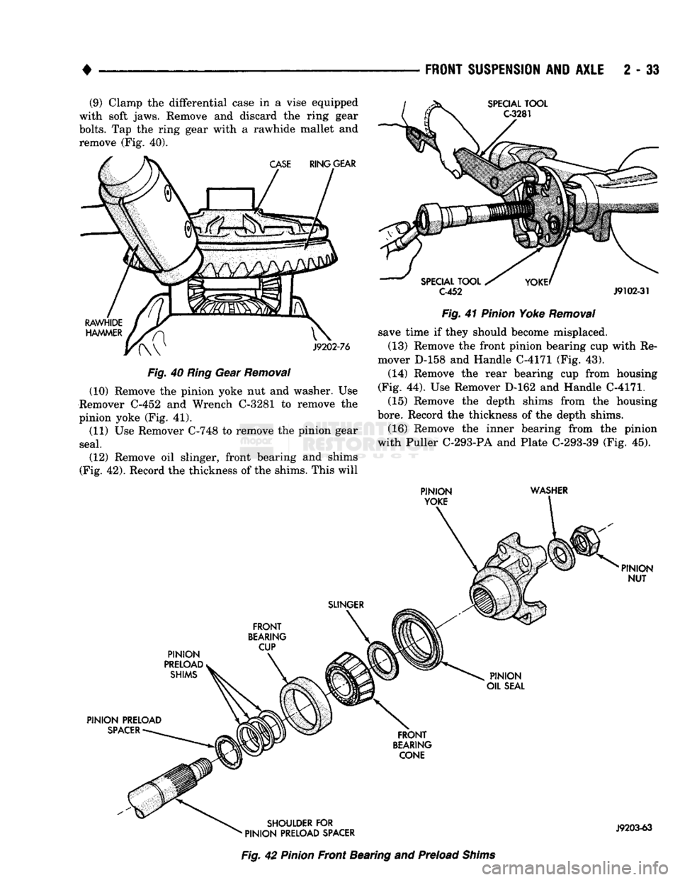
2 - 33 (9) Clamp the differential case in a vise equipped
with soft jaws. Remove and discard the ring gear
bolts.
Tap the ring gear with a rawhide mallet and
remove (Fig. 40).
RING
GEAR SPECIAL
TOOL
C-3281
SPECIAL
TOOL
C-452
J9102-31
RAWHIDE
HAMMER
J9202-76
Fig.
40
Ring
Gear
Removal
(10) Remove the pinion yoke nut and washer. Use
Remover C-452 and Wrench C-3281 to remove the
pinion yoke (Fig. 41). (11) Use Remover C-748 to remove the pinion gear
seal.
(12) Remove oil slinger, front bearing and shims
(Fig. 42). Record the thickness of the shims. This will
Fig.
41
Pinion
Yoke
Removal
save time if they should become misplaced.
(13) Remove the front pinion bearing cup with Re
mover D-158 and Handle C-4171 (Fig. 43). (14) Remove the rear bearing cup from housing
(Fig. 44). Use Remover D-162 and Handle C-4171.
(15) Remove the depth shims from the housing
bore. Record the thickness of the depth shims.
(16) Remove the inner bearing from the pinion
with Puller C-293-PA and Plate C-293-39 (Fig. 45).
PINION
YOKE WASHER
SLINGER
PINION
PRELOAD SHIMS
FRONT
BEARING CUP
PINION
PRELOAD
SPACER
PINION
NUT
PINION
OIL
SEAL
FRONT
BEARING CONE
SHOULDER
FOR
•
PINION
PRELOAD SPACER
J9203-63
Fig.
42
Pinion
Front Bearing and Preload
Shims
Page 92 of 1502
•
FRONT
SUSPENSION
AND
AXLE
2 - 39
Fig.
59
Pinion
Height
Block
Against
Arbor
Fig.
60
Pinion
Gear Depth Measurement
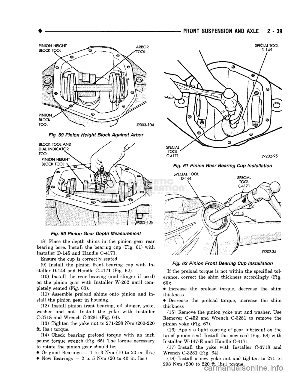
(8) Place the depth shims in the pinion gear rear
bearing bore. Install the bearing cup (Fig. 61) with Installer D-145 and Handle C-4171.
Ensure the cup is correctly seated. (9) Install the pinion front bearing cup with In
staller D-144 and Handle C-4171 (Fig. 62).
(10) Install the rear bearing (and slinger if used)
on the pinion gear with Installer W-262 until com
pletely seated (Fig. 63).
(11) Assemble preload shims onto pinion and in
stall the pinion gear in housing.
(12) Install pinion front bearing, oil slinger, yoke,
washer and nut. Install the yoke with Installer C-3718 and Wrench C-3281 (Fig. 64).
(13) Tighten the yoke nut to 271-298 N-m (200-220
ft. lbs.) torque. (14) Check bearing preload torque with an inch
pound torque wrench (Fig. 65). The torque necessary
to rotate the pinion gear should be;
• Original Bearings — 1 to 3 N*m (10 to 20 in. lbs.)
• New Bearings — 2 to 5 N*m (20 to 40 in. lbs.)
SPECIAL
TOOL
C-4171
J9202-95
Fig.
61
Pinion
Rear Bearing Cup
Installation
SPECIAL
TOOL
D-144
SPECIAL Fig.
62
Pinion
Front Bearing Cup
Installation
If the preload torque is not within the specified tol
erance, correct the shim thickness accordingly (Fig.
66);
• Increase the preload torque, decrease the shim
thickness
• Decrease the preload torque, increase the shim
thickness
(15) Remove the pinion yoke nut and washer. Use
Remover C-452 and Wrench C-3281 to remove the
pinion yoke (Fig. 67).
(16) Apply a light coating of gear lubricant on the
lip of pinion seal. Install the new seal (Fig. 68) with
Installer W-147-E and Handle C-4171
(17) Install the yoke with Installer C-3718 and
Wrench C-3281 (Fig. 64). (18) Install a new yoke nut and tighten to 271 to
298 N-m (200 to 220 ft. lbs.) torque.