1993 DODGE TRUCK reset
[x] Cancel search: resetPage 58 of 1502

•
FRONT
SUSPENSION
AND
AXLE
2 - 5 (4) Front wheels for excessive radial, lateral
runout and unbalance. Refer to Group 22, Wheels and Tires for diagnosis information.
(5) Suspension components for wear and noise. Check
components for correct torque. Refer to Groups 2 and 3, Suspension and Axle for additional information.
WHEEL
ALIGNMENT
MEASUREMENTS/ADJUSTMENTS
The front wheel alignment positions must be set to
the specified limits. This will prevent abnormal tire
tread wear. The equipment manufacturer's recommenda
tions for use of their
equipment
should always
be followed. All
damaged
front suspension sys
tem components
should
be replaced. Do not at tempt to straighten any
bent
component.
CAMBER AND CASTER-2WD VEHICLES Camber and caster angle adjustments involve repo
sitioning the upper suspension arm cam adjustment
bolts (Fig. 2). Alignment adjustments are accom
plished by loosening the nuts and changing the posi
tion of the cam bolt.
(1) Remove all foreign material from the adjust
ment bolt threads.
(2) Record the camber and caster measurements
before loosening the adjustment bolt nuts.
(3) The camber angle should be adjusted as near as
possible to the preferred angle. The caster should be
the same at both sides of the vehicle. Refer to the Specifications chart.
CAMBER AND CASTER—4WD VEHICLES For 4WD vehicles, the correct wheel camber (verti
cal tilt) angle is factory preset at zero degree (0°).
Camber cannot be altered by adjustment.
CAUTION: Do not attempt to
adjust
the
camber
an
gle by
heating
or bending the axle or any
suspen
sion
component. If camber angle is
incorrect,
the
component(s)
causing
an
incorrect
angle must be replaced.
(1) It is important that the camber (vertical tilt)
angle be the same for both front wheels.
(2) The camber angle should be measured with ac
curate wheel alignment equipment. The acceptable
range is -1° to +1°. Refer to the Specifications chart.
Road test the vehicle and observe the steering
wheel return-to-center position. Before road testing,
check
and
correct
the tire
inflation pressures. Inflate
both
of the front tires
with exactly the
same
pressure.
During the road test, make vehicle turns to both
the left and right. If the steering wheel returns to
ward the center position unassisted, the caster angle is correct. However, if the steering wheel does not re turn toward the center position unassisted, an incor
rect caster angle is probable.
(1) The caster angle is factory preset at positive
two degrees
(
+
2°).
The acceptable range is +1/2° to +
3
1/2°.
(2) The caster angle should be measured with ac
curate wheel alignment equipment.
(3) Caster angle can be adjusted by installing ta
pered shims between the front axle pads and the spring brackets. The caster angle should be adjusted
as near as possible to the preferred angle.
(4) Record the caster measurement before remov
ing the original shims from the spring pads.
(5) The caster should be the same at both sides of
the vehicle. Refer to the Specifications chart.
RN1030
Fig.
2 Caster &
Camber
Adjustment Location—2WD
Vehicles
WHEEL TOE POSITION The wheel toe position adjustment should be the fi
nal front wheel alignment adjustment. In all in stances, follow the equipment manufacturer's
recommended procedure.
(1) Secure the steering wheel with the front wheels
in the straight-ahead position. For vehicles equipped
with power steering, start the engine before straight ening the wheels.
With power steering, the engine should be op
erating during the wheel toe position adjust
ment.
(2) Loosen the tie rod adjustment sleeve clamp
bolts (Fig. 3).
(3) Adjust the wheel toe position by rotating the
tie rod adjustment sleeve (Fig. 3). Rotate each tie-rod end in the direction of
sleeve rotation during the adjustment (Fig. 3).
This will ensure that both tie-rod ends are at the center of their travel.
(4) If applicable, turn the ignition switch off.
Page 254 of 1502
CLUTCH
6 - 1
CLUTCH
CONTENTS
page
CLUTCH
DIAGNOSIS
2
CLUTCH
COMPONENTS
MECHANICAL COMPONENTS
The clutch mechanism
in
AD
models with
a gas or
diesel engine consists
of a
single, dry-type clutch disc and
a
diaphragm style clutch cover.
A
hydraulic
linkage
is
used
to
engage/disengage
the
clutch disc
and cover.
The transmission input shaft
is
supported
in the
crankshaft
by a
bearing.
A
sleeve type release bear
ing
is
used
to
operate
the
clutch cover pressure plate.
The release bearing
is
operated
by a
release fork
in
the clutch housing.
The
fork pivots
on a
ball stud
mounted inside
the
housing.
The
release fork
is
actu ated
by a
hydraulic slave cylinder mounted
in the
housing.
The
slave cylinder
is
operated
by a
clutch master cylinder mounted
on the
dash panel.
The
cyl
inder push
rod is
connected
to the
clutch pedal.
The clutch disc
has
cushion springs
in the
disc
hub.
The clutch disc facing
is
riveted
to the hub. The
fac ing
is
made from
a
non-asbestos material.
The
clutch
cover pressure plate
is a
diaphragm type with
a one-
piece spring
and
multiple release fingers.
The
pres sure plate release fingers
are
preset during
manufacture
and are not
adjustable.
A
265 mm
clutch disc
and
cover
are
used
in
models
with
a 3.9L
engine.
A 280 mm
clutch disc
and
cover are used
in
models with
a 5.2L, or
5.9L engine.
A
330 mm
clutch disc
and
cover
are
used
in
models
equipped with
the
optional
5.9L
Cummins diesel
en
gine.
Some diesel models
are
also equipped with
a
clutch pedal interlock switch.
The
switch
is in
circuit
with
the
starter relay
and is
actuated
by the
clutch
pedal
and
push
rod. The
clutch pedal must
be
fully depressed
in
order
to
start
the
engine.
HYDRAULIC LINKAGE COMPONENTS
The hydraulic linkage consists
of a
remote reser
voir, clutch master cylinder, clutch slave cylinder and interconnecting fluid lines.
The clutch master cylinder
is
connected
to the
clutch pedal
and the
slave cylinder
is
connected
to
the clutch release fork.
The
master cylinder
is
mounted
on the
drivers' side
of the
dash panel adja
cent
to the
brake master cylinder.
page
CLUTCH
SERVICE
11
CLUTCH LINKAGE FLUID
The clutch fluid reservoir, master cylinder, slave
cylinder
and
fluid lines
are
prefilled with fluid
at the
factory during assembly operations. The hydraulic system should
not
require additional
fluid under normal circumstances.
In
fact,
the
reser
voir fluid level will actually increase
as
normal clutch wear occurs.
For
this reason,
it is
impor
tant
to
avoid overfilling,
or
removing fluid from
the reservoir. If inspection
or
diagnosis indicates additional fluid
may
be
needed,
use
Mopar brake fluid,
or an
equiv
alent meeting
SAE and DOT
standards J1703
and
DOT
3. Do not use any
other type
of
fluid.
CLUTCH
COMPONENT LUBRICATION
Proper clutch component lubrication
is
important
to satisfactory operation.
The
correct lubricant
and
not overlubricating
are
equally important. Apply rec
ommended lubricant sparingly
to
avoid disc
and
pres sure plate contamination. Clutch
and
transmission components requiring
lu
brication
are:
• pilot bearing
• release lever pivot ball stud
• release lever contact surfaces
• clutch disc
hub
splines
• clutch pedal pivot shaft bore
• clutch pedal bushings
• input shaft splines
• input shaft pilot
hub
• transmission front bearing retainer slide surface Do
not
apply grease
to any
part
of the
clutch
cover,
or
disc.
RECOMMENDED LUBRICANTS
Use Mopar multi-purpose grease
for the
clutch
pedal bushings
and
pivot shaft.
Use
Mopar high tem
perature grease
(or
equivalent)
for all
other lubrica
tion requirements. Apply recommended amounts
and
do
not
over lubricate.
Page 383 of 1502
8E
- 2
INSTRUMENT PANEL
AND
GAUGES
•
TEMPERATURE AND
OIL
INDICATING SYSTEM
(FIG.
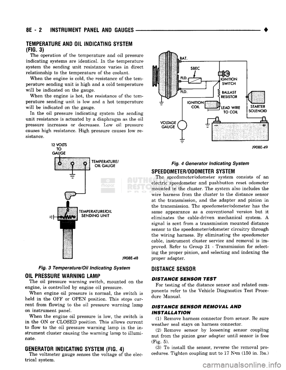
3) The operation of the temperature and oil pressure
indicating systems are identical. In the temperature
system the sending unit resistance varies in direct
relationship to the temperature of the coolant. When the engine is cold, the resistance of the tem
perature sending unit is high and a cold temperature
will be indicated on the gauge. When the engine is hot, the resistance of the tem
perature sending unit is low and a hot temperature
will be indicated on the gauge. In the oil pressure indicating system the sending
unit resistance is actuated by a diaphragm as the oil
pressure increases or decreases. Low oil pressure causes high resistance. High pressure causes low re
sistance. 12
VOLTS
TO
GAUGE
TEMPERATURE/
OIL GAUGE
TEMPERATURE/OIL SENDING
UNIT
J908E-48
Fig. 3 Temperature/Oil indicating System
OIL
PRESSURE
WARNING LAMP
The oil pressure warning switch, mounted on the
engine, is controlled by engine oil pressure. When engine oil pressure is normal, the switch is
held in the OFF or OPEN position. This stops cur
rent from flowing to the oil pressure warning lamp
on instrument panel. When the engine oil pressure is low, the switch is
in the ON or CLOSED position. This allows current
to flow to the oil pressure warning lamp in the in strument cluster causing the warning lamp to illumi
nate.
GENERATOR
INDICATING
SYSTEM
(FIG. 4)
The voltmeter gauge senses the voltage of the elec
trical system.
VOLTAGE
/*
GAUGE
P/
J908E-49 Fig. 4 Generator Indicating System
SPEEDOMETER/ODOMETER SYSTEM
The speedometer/odometer system consists of an
electric speedometer and pushbutton reset odometer
mounted in the cluster. The system also includes the
wire harness from the cluster to the distance sensor at the transmission, and the adapter and pinion in
the transmission. The speedometer/odometer has the same appearance as a conventional version but it
eliminates the cable-driven mechanical system. A signal is sent from a transmission mounted distance
sensor to the speedometer/odometer circuitry through
the wiring harness. By eliminating the speedometer cable, instrument cluster service and removal is im
proved. Refer to Group 21 - Transmission for select ing the proper pinion, and selecting and indexing the
proper adapter.
DISTANCE
SENSOR
DISTANCE SENSOR TEST For testing of the distance sensor and related com
ponents refer to the Vehicle Diagnostics Test Proce dure Manual.
DISTANCE SENSOR REMOVAL AND INSTALLATION (1) Remove harness connector from sensor. Be sure
weather seal stays on harness connector. (2) Remove sensor by loosening sensor coupling
nut from the pinion gear adapter until sensor is free (Fig. 5).
(3) To install the sensor, reverse the removal pro
cedures. Tighten coupling nut to 17 N»m (150 in. lbs.)
Page 461 of 1502
8P
- 2 POWER DOOR LOCKS
• SERVICE PROCEDURES
DOOR LOCK MOTOR REPLACEMENT
REMOVAL
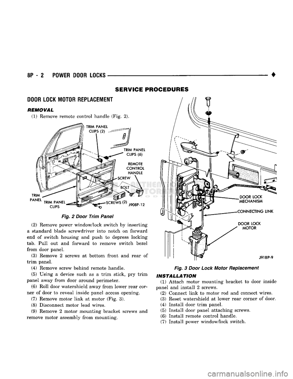
(1) Remove remote control handle (Fig. 2).
TRIM
PANEL
TRIM
PANEL
CLIPS
(6)
REMOTE
CONTROL
HANDLE
SCREW
TRIM
PANEL
CLIPS
J908P-12
Fig.
2
Door
Trim
Panel
(2) Remove power window/lock switch by inserting
a standard blade screwdriver into notch on forward
end of switch housing and push to depress locking
tab.
Pull out and forward to remove switch bezel
from door panel.
(3) Remove 2 screws at bottom front and rear of
trim panel.
(4) Remove screw behind remote handle.
(5) Using a device such as a trim stick, pry trim
panel away from door around perimeter.
(6) Roll door watershield away from lower rear cor
ner of door to reveal inside panel access opening.
(7) Remove motor link at motor (Fig. 3).
(8) Disconnect motor lead wires.
(9) Remove 2 motor mounting bracket screws and
remove motor assembly from mounting.
DOOR
LOCK
MOTOR
J918P-9
Fig.
3
Door
Lock
Motor Replacement
INSTALLATION
(1) Attach motor mounting bracket to door inside
panel and install 2 screws. (2) Connect link to motor rod and connect wires.
(3) Reset watershield at lower rear corner of door.
(4) Install door trim panel. (5) Install door panel attaching screws.
(6) Install remote control handle.
(7) Install power window/lock switch.
Page 479 of 1502
8W
- 4
WIRING
DIAGRAMS
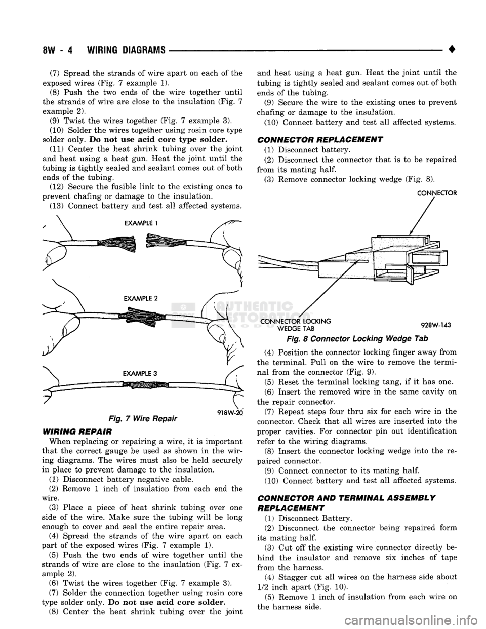
(7) Spread
the
strands
of
wire apart
on
each
of the
exposed wires
(Fig. 7
example
1).
(8) Push
the two
ends
of the
wire together until
the strands
of
wire
are
close
to the
insulation
(Fig. 7
example
2).
(9) Twist
the
wires together
(Fig. 7
example
3).
(10) Solder
the
wires together using rosin core type
solder only.
Do not use
acid core type solder.
(11) Center
the
heat shrink tubing over
the
joint
and heat using
a
heat
gun.
Heat
the
joint until
the
tubing
is
tightly sealed
and
sealant comes
out of
both ends
of the
tubing. (12) Secure
the
fusible link
to the
existing ones
to
prevent chafing
or
damage
to the
insulation.
(13) Connect battery
and
test
all
affected systems.
Fig.
7
Wire Repair
918W-20
WIRING REPAIR When replacing
or
repairing
a
wire,
it is
important
that
the
correct gauge
be
used
as
shown
in the
wir ing diagrams.
The
wires must also
be
held securely
in place
to
prevent damage
to the
insulation.
(1) Disconnect battery negative cable.
(2) Remove
1
inch
of
insulation from each
end the
wire.
(3) Place
a
piece
of
heat shrink tubing over
one
side
of the
wire. Make sure
the
tubing will
be
long
enough
to
cover
and
seal
the
entire repair area.
(4) Spread
the
strands
of the
wire apart
on
each
part
of the
exposed wires
(Fig. 7
example
1).
(5)
Push
the two
ends
of
wire together until
the
strands
of
wire
are
close
to the
insulation
(Fig. 7 ex
ample
2).
(6) Twist
the
wires together
(Fig. 7
example
3).
(7) Solder
the
connection together using rosin core
type solder only.
Do not use
acid core solder.
(8)
Center
the
heat shrink tubing over
the
joint and heat using
a
heat
gun.
Heat
the
joint until
the
tubing
is
tightly sealed
and
sealant comes
out of
both
ends
of the
tubing.
(9) Secure
the
wire
to the
existing ones
to
prevent
chafing
or
damage
to the
insulation.
(10) Connect battery
and
test
all
affected systems.
CONNECTOR REPLACEMENT (1) Disconnect battery.
(2) Disconnect
the
connector that
is to be
repaired
from
its
mating
half.
(3) Remove connector locking wedge
(Fig. 8).
CONNECTOR
CONNECTOR
LOCKING
WEDGE
TAB
928W-143
Fig.
8
Connector Locking Wedge
Tab
(4) Position
the
connector locking finger away from
the terminal. Pull
on the
wire
to
remove
the
termi nal from
the
connector
(Fig. 9).
(5) Reset
the
terminal locking tang,
if it has one.
(6) Insert
the
removed wire
in the
same cavity
on
the repair connector.
(7) Repeat steps four thru
six for
each wire
in the
connector. Check that
all
wires
are
inserted into
the
proper cavities.
For
connector
pin out
identification refer
to the
wiring diagrams.
(8) Insert
the
connector locking wedge into
the re
paired connector.
(9) Connect connector
to its
mating
half.
(10) Connect battery
and
test
all
affected systems.
CONNECTOR
AND
TERMINAL ASSEMBLY
REPLACEMENT
(1) Disconnect Battery.
(2) Disconnect
the
connector being repaired form
its mating
half.
(3)
Cut off the
existing wire connector directly
be
hind
the
insulator
and
remove
six
inches
of
tape
from
the
harness.
(4) Stagger
cut all
wires
on the
harness side about
1/2
inch apart
(Fig. 10).
(5) Remove
1
inch
of
insulation from each wire
on
the harness side.
Page 547 of 1502
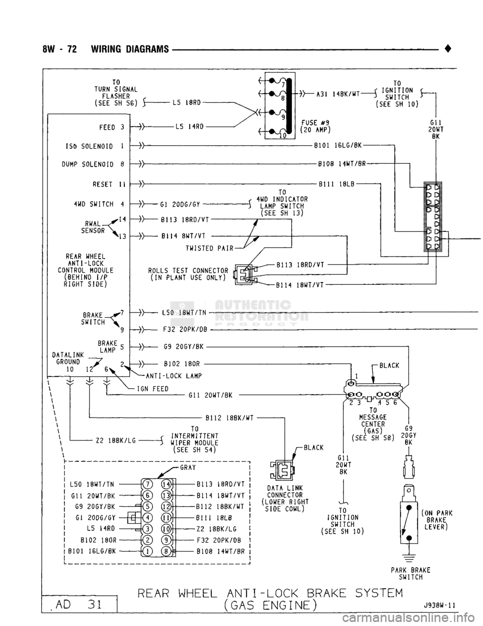
8W
- 72
WIRING DIAGRAMS
TO
TURN SIGNAL
FLASHER
r
(SEE
SH 56) Y
L5
18R0
FEED
3
ISO
SOLENOID
1
DUMP SOLENOID
8
RESET
11
4WD SWITCH
4
RWAL
SENSOR
»\3
REAR
WHEEL ANTI-LOCK
CONTROL MODULE (BEHIND
I/P
RIGHT SIDE)
BRAKE
SWITCH
BRAKE
I
AMP
DATALINK
GROUND
~~y 10 12 6
-»- -L5
14RD
TO
»~-A31
14BK/WT—j
»gjj}{J" J-
(SEE
SH 10)
FUSE
#9
(20 AMP)
Gil
20WT
BK
•B101 16LG/BK-
-yy -B108 14WT/BR-
Bill
18LB—-
-»-
Gl 20DG/GY
B113
18RD/VT
B114
8WT/VT
TO
<
4WD
INDICATOR
")
LAMP SWITCH
(SEE
SH 13)
TWISTED PAIR
ROLLS
TEST CONNECTOR
*
(IN PLANT
USE
ONLY)
pa
3
D
D
3
D • 2J3
B114
18WT/VT•
-»-
L50
18WT/TN
-
F32 20PK/DB G9 20GY/BK
-
B102
180R
^ANTI-LOCK LAMP
IGN FEED Gil 20WT/BK
B112 18BK/WT
12
18BK/LG TO
INTERMITTENT
WIPER MODULE
(SEE
SH 54)
GRAY
L50
18WT/TN
Gil 20WT/BK G9 20GY/BK
Gl
2QDG/GY
L5
14RD
B102
180R
B101 16LG/BK -B113
18RD/VT
-B114
18WT/VT
-B112 18BK/WT
-Bill
18LB
-12
18BK/LG
•
F32
20PK/DB
•B108
14WT/BR
BLACK
2
3^456
TO
MESSAGE
CENTER
rQ
SEE
SH 58)
2g»Y
DATA LINK
CONNECTOR
(LOWER RIGHT
SIDE
COWL) Gil
20WT
BK
TO
IGNITION SWITCH
(SEE
SH 10)
(ON PARK
BRAKE
LEVER)
PARK
BRAKE SWITCH
AD
31
REAR
WHEEL ANT I-LOCK BRAKE
SYSTEM
(GAS
ENGINE)
J938W-11
Page 548 of 1502
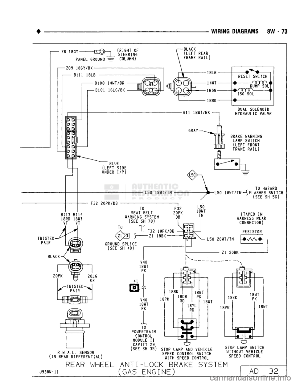
WIRING DIAGRAMS SW - 73
(RIGHT OF
STEERING
BLACK
(LEFT
REAR
FRAME
RAIL)
RESET
SWITCH DUMP SOL
#-/YYTP
i
ISO
SOL
DUAL SOLENOID
HYDRAULIC VALVE
BRAKE
WARNING LAMP SWITCH ;LEFT FRONT
FRAME
RAIL)
„ TO HAZARD
L50
18WT/TN
—(FLASHER SWITCH
(SEE
SH 56)
R.W.A.L.
SENSOR
(IN REAR DIFFERENTIAL) TO
POWERTRAIN
CONTROL
MODULE II CAVITY 29
(SEE
SH 35) O
STOP
LAMP AND VEHICLE
SPEED
CONTROL SWITCH
WITH
SPEED
CONTROL
STOP
LAMP SWITCH
WITHOUT
VEHICLE
SPEED
CONTROL
J938W-11
REAR
WHEEL ANTI-LOCK BRAKE SYSTEM
(GAS ENGINE) AD 32
Page 549 of 1502
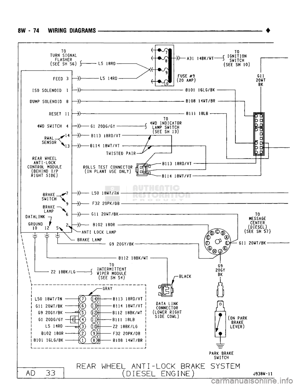
SW
- 74
WIRING DIAGRAMS
TO
TURN SIGNAL
FLASHER
f
(SEE
SH 56) y
L5
18R0
FEED
3
ISO
SOLENOID
1
DUMP
SOLENOID
8
RESET
11
4WD SWITCH
4
.14
43 RWAL
SENSOR
<
REAR
WHEEL
ANTI-LOCK
CONTROL MODULE (BEHIND
I/P
RIGHT SIDE)
BRAKE
SWITCH
BRAKE
LAMP
DATALINK
GROUND
10
12
7
5> -L5
14RD
A31 14BK/WT
TO
J
IGNITION
>
SWITCH
(SEE
SH 10)
FUSE
#9
'20 AMP)
8101 16LG/BK
B108 14WT/BR
Bill
18LB
Gl 20DG/GY
B113 18RD/VT• TO
<
4WD
INDICATOR
-}
LAMP SWITCH
(SEE
SH 13)
-»-
-B114
18WT/VT
TWISTED PAIR
ROLLS
TEST CONNECTOR
m
(IN PLANT
USE
ONLY)
%
B114
18WT/VT
L50
18WT/TN
•
F32 20PK/DB
Gil 20WT/BK-
B102
180R •
-ANTI LOCK LAMP
BRAKE
LAMP G9 20GY/BK-
Bl12 18BK/WT Z2 18BK/LG• TO
INTERMITTENT
WIPER
MODULE
(SEE
SH 54)
-GRAY
L50
18WT/TN
Gil 20WT/BK G9 20GY/BK Gl 20DG/GY L5
14RD
B102
180R
B101 16LG/BK
to
(g)S
-B113 18RD/VT
-B114
18WT/VT
-B112 18BK/WT
Bill
18LB
-Z2 18BK/LG F32 20PK/DB
B108 14WT/BR BLACK
DATA LINK
CONNECTOR
(LOWER RIGHT
SIDE
COWL) TO
MESSAGE
CENTER
(DIESEL)
(SEE
SH 57)
Gil 20WT/BK-
(ON PARK
BRAKE
LEVER)
PARK
BRAKE
SWITCH AD
33
REAR
WHEEL ANT I--LOCK BRAKE SYSTEM
(DIESEL
ENGINE)
J938W-11