1993 DODGE TRUCK grounds
[x] Cancel search: groundsPage 476 of 1502
•
WIRING DIAGRAMS
8W
- 1
CONTENTS
page page
COMPONENT IDENTIFICATION
.............
9
SPLICE LOCATIONS
29
GENERAL
INFORMATION
1
WIRING DIAGRAMS AD-BODY
37
GENERAL
INFORMATION
INDEX
page
Circuit
Identification
2
Component
Identification
3
Connectors
3
Fusible Links
3
Harness
Repair
3
Locating
A
System
or
Component
2
page
Secondary
Ignition
Wiring
1
Splice Locations
3
Symbols
and
Fuses
5
Troubleshooting
Wiring
Problems
3
Wire Code
Identification
2
Wiring
Diagram Sheets
and
Indexes
1
The wiring diagrams contain
the
latest information
available
at
time
of
publication. Throughout
out
this
group references
may
be
made
to a
particular vehicle
by letter
or
number designation.
A
chart showing
the
breakdown
of
these designations
is
included
in the
Introduction Section
of
this service manual.
SECONDARY
IGNITION WIRING
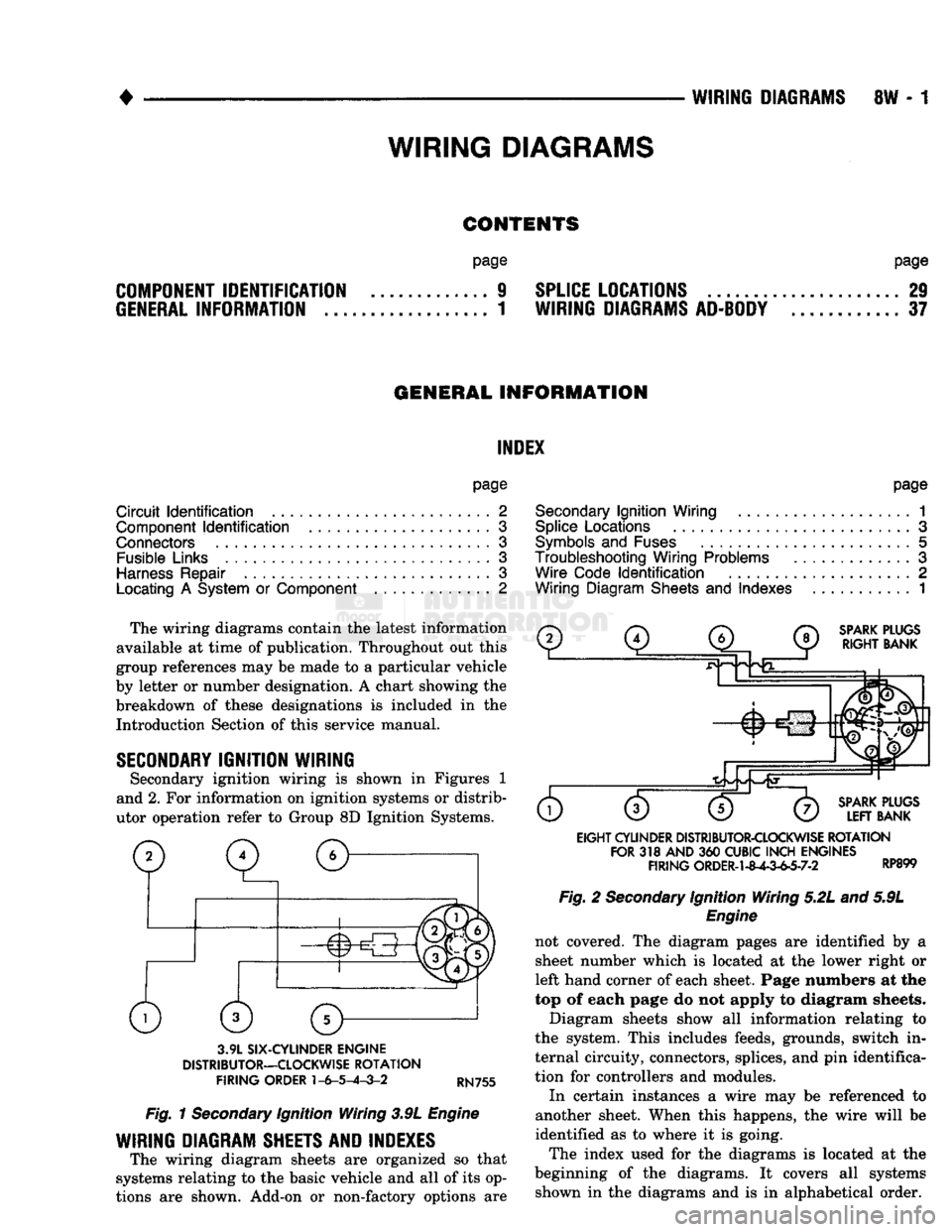
Secondary ignition wiring
is
shown
in
Figures
1
and 2.
For
information
on
ignition systems
or
distrib
utor operation refer
to
Group
8D
Ignition Systems.
SPARK
PLUGS
RIGHT
BANK
3.9L
SIX-CYLINDER
ENGINE
DISTRIBUTOR—CLOCKWISE
ROTATION
FIRING
ORDER
1-6-5-4-3-2
RN755
Fig.
1
Secondary
Ignition Wiring 3.9L
Engine
WIRING DIAGRAM SHEETS AND INDEXES
The wiring diagram sheets
are
organized
so
that
systems relating
to the
basic vehicle
and all of
its op
tions
are
shown. Add-on
or
non-factory options
are
SPARK
PLUGS
LEFT
BANK
EIGHT
CYLINDER
DISTRIBUTOR-CLOCKWISE
ROTATION
FOR
318
AND
360
CUBIC
INCH
ENGINES
FIRING
ORDER-1-8^-3-63-7-2 RP899 Fig.
2
Secondary
Ignition Wiring 5.2L and 5.9L
Engine
not covered.
The
diagram pages
are
identified
by a
sheet number which
is
located
at the
lower right
or
left hand corner
of
each sheet. Page numbers
at the
top
of
each page
do not
apply
to
diagram sheets.
Diagram sheets show
all
information relating
to
the system. This includes feeds, grounds, switch
in
ternal circuity, connectors, splices,
and
pin
identifica
tion
for
controllers
and
modules.
In certain instances
a
wire
may be
referenced
to
another sheet. When this happens,
the
wire will
be
identified
as to
where
it is
going.
The index used
for the
diagrams
is
located
at the
beginning
of the
diagrams.
It
covers
all
systems shown
in the
diagrams
and is in
alphabetical order.
WIRING
DIAGRAMS
Page 477 of 1502
8W
- 2
WIRING
DIAGRAMS
•
WIRE CODE
IDENTIFICATION
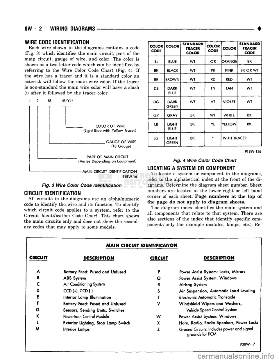
Each wire shown in the diagrams contains a code
(Fig. 3) which identifies the main circuit, part of the
main circuit, gauge of wire, and color. The color is shown as a two letter code which can be identified by
referring to the Wire Color Code Chart (Fig. 4). If
the wire has a tracer and it is a standard color an asterisk will follow the main wire color. If the tracer
is non-standard the main wire color will have a slash (/) after it followed by the tracer color. 18
LB/YL*
COLOR
OF
WIRE
(Light
Blue
with
Yellow
Tracer)
.
GAUGE
OF
WIRE
(18
Gauge)
PART
OF
AAAIN CIRCUIT
(Varies
Depending
on
Equipment)
AAAIN CIRCUIT
IDENTIFICATION
918W-16
Fig.
3
Wire
Color
Code
Identification
CIRCUIT IDENTIFICATION
All circuits in the diagrams use an alpha/numeric
code to identify the, wire and its function. To identify
which circuit code applies to a system, refer to the
Circuit Identification Code Chart. This chart shows
the main circuits only and does not show the second ary codes that may apply to some models.
COLOR
CODE COLOR
STANDARD
TRACER
COLOR COLOR
CODE
COLOR
STANDARD
TRACER
CODE
BL BLUE WT
OR ORANGE
BK
BK
BLACK
WT PK
PINK
BK
OR WT
BR
BROWN
WT RD
RED WT
DB DARK
BLUE WT
TN
TAN WT
DG DARK
GREEN WT
VT
VIOLET
WT
GY GRAY
BK
WT
WHITE
BK
LB
LIGHT
BLUE
BK
YL YELLOW
BK
LG
LIGHT
GREEN
BK
*
WITH
TRACER
918W-136
Fig.
4
Wire
Color
Code
Chart
LOCATING
A
SYSTEM
OR
COMPONENT
To locate a system or component in the diagrams,
refer to the alphabetical index at the front of the di agrams. Determine the diagram sheet number. Sheet
numbers are located at the lower right or left hand
corner of each sheet. Page numbers at the top of
the page do not apply to diagram sheets. The diagram index identifies the main system and
all components that relate to that system. There are
also sections of the index that identify specific com
ponents only (for example modules, lamps, etc.). Re-
MAIN
CIRCUIT IDENTIFICATION
CIRCUIT
DESCRIPTION
CIRCUIT
DESCRIPTION
A
Battery
Feed: Fused and Unfused
P
Power
Assist
System:
Locks,
Mirrors
B
ABS
System Q Power
Assist
System: Windows
C
Air Conditioning System
R
Airbag System
D
CCD
(+),
CCD
(-)
S
Air Suspension, Automatic Load Leveling
E
Interior
Lamp
Illumination
T Electronic Automatic Transaxle
F
Battery
Feed: Fused and Unfused
V
Windshield Wipers and Washers,
G
Sensors,
Sending Units, Switches Vehicle Speed Control System
K
Powertrain
Central
Module W Power
Assist
System: Windows
L
Exterior
Lighting, Stop Lamp Switch
X
Horn, Radio, Radio Speakers, Power Locks
M
Interior
Lamps
Z
Ground Circuits: Includes power and signal
Interior
Lamps
grounds
for PCM
938W-17
Page 863 of 1502
14 - 44
FUEL
SYSTEM
•
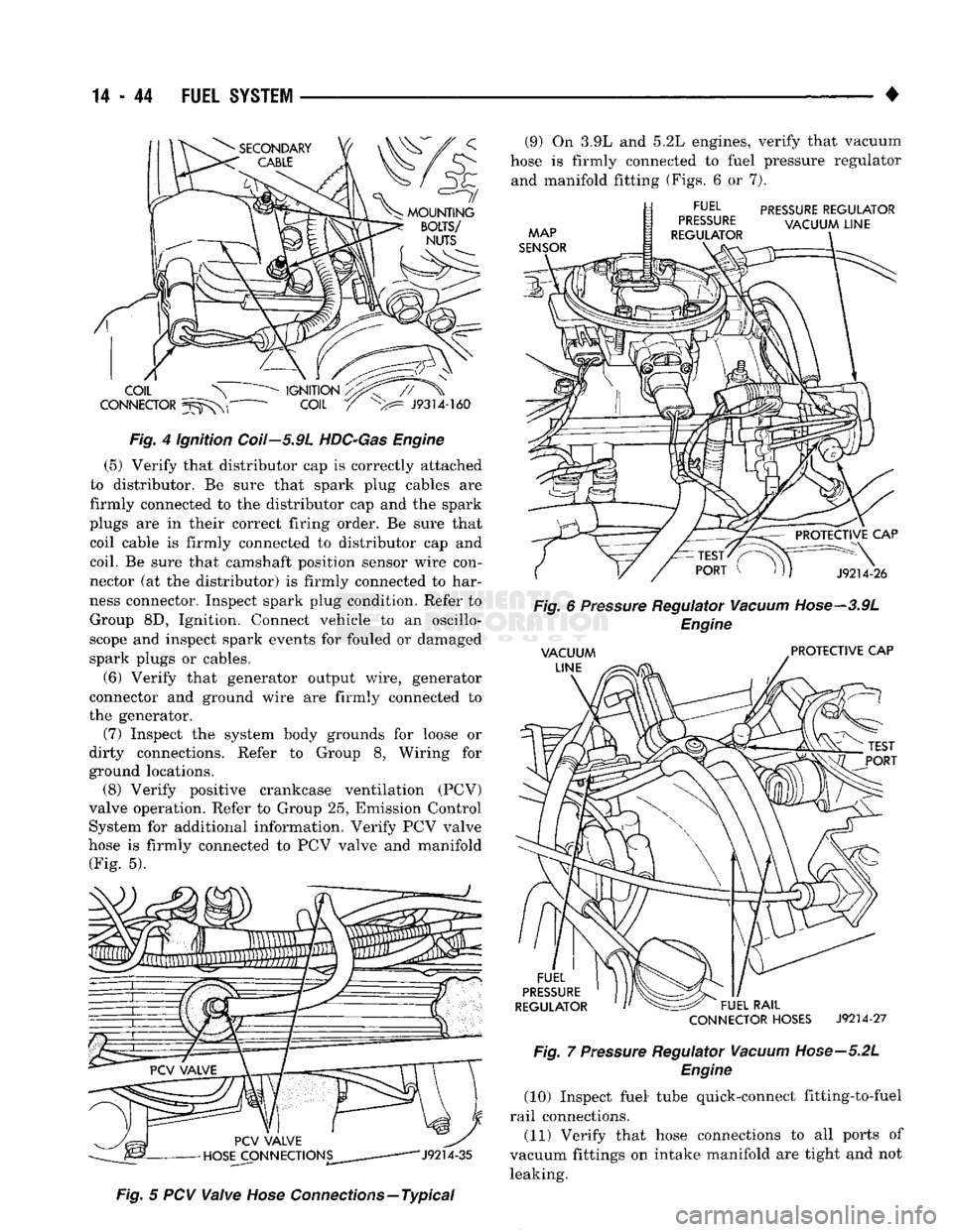
Fig.
4 ignition Coil—5.9L
HDC-Gas
Engine
(5) Verify that distributor cap is correctly attached
to distributor. Be sure that spark plug cables are
firmly connected to the distributor cap and the spark
plugs are in their correct firing order. Be sure that coil cable is firmly connected to distributor cap and
coil. Be sure that camshaft position sensor wire con
nector (at the distributor) is firmly connected to har
ness connector. Inspect spark plug condition. Refer to Group 8D, Ignition. Connect vehicle to an oscillo
scope and inspect spark events for fouled or damaged
spark plugs or cables.
(6) Verify that generator output wire, generator
connector and ground wire are firmly connected to
the generator. (7) Inspect the system body grounds for loose or
dirty connections. Refer to Group 8, Wiring for
ground locations. (8) Verify positive crankcase ventilation (PCV)
valve operation. Refer to Group 25, Emission Control System for additional information. Verify PCV valve
hose is firmly connected to PCV valve and manifold (Fig. 5).
Fig.
5 PCV
Valve
Hose
Connections—Typical (9) On 3.9L and 5.2L engines, verify that vacuum
hose is firmly connected to fuel pressure regulator and manifold fitting (Figs. 6 or 7).
CONNECTOR
HOSES
J9214-27
Fig.
7
Pressure
Regulator
Vacuum
Hose—5.2L
Engine
(10) Inspect fuel* tube quick-connect fitting-to-fuel
rail connections. (11) Verify that hose connections to all ports of
vacuum fittings on intake manifold are tight and not leaking.
Page 1086 of 1502
•
AUTOMATIC TRANSiISSiOi-32RH/38RH/37RH/42RH/4eRH
21 - 81 AUTOMATIC TRANSMISSION DIAGNOSIS AND TESTING
INDEX
page
Air Testing Clutch
and
Band Operation
91
Analyzing
the
Road Test
87
Converter Housing Fluid Leak Diagnosis
.......
92
Converter
Stall
Test
90
Diagnosis
Charts
and
Hydraulic Flow Diagrams
. . 95
Fluid Contamination
86
Fluid Level
and
Condition
85
GENERAL
INFORMATION
The diagnosis
and
testing information
in
this sec
tion applies
to
three
and
four speed models alike.
Di
agnosis
and
test procedures apply
to all
models
except where indicated. Diagnosis information that
only applies
to
42RH/46RH models
is
noted.
Automatic transmission problems
can be a
result
of
poor engine performance, incorrect fluid level, incor
rect linkage adjustment, band
or
hydraulic control
pressure adjustments, hydraulic system malfunctions
or electrical/mechanical component malfunctions.
Begin diagnosis
by
checking
the
easily accessible
items such
as:
fluid level
and
condition, linkage
ad
justments
and
electrical connections
on
4-speed mod
els.
A
road test will determine
if
further diagnosis
is
necessary. Procedures outlined
in
this section should
be
per
formed
in the
following sequence
to
realize
the
most accurate results:
• Preliminary diagnosis
• Fluid Level
and
condition • Linkage Adjustment
• Road test
• Hydraulic pressure test • Stall test
•
Air
pressure tests
• Leak Tests
• Analyze test results
and
consult diagnosis charts
PRELIMINARY
DIAGNOSIS
Two basic procedures
are
required.
One
procedure
for vehicles that
are
driveable
and an
alternate pro cedure
for
disabled vehicles (will
not
back
up or
move forward).
Vehicle
Is
Driveable
(1) Check fluid level
and
condition.
(2) Adjust throttle
and
gearshift linkage
if
com
plaint
was
based
on
delayed, erratic,
or
harsh shifts.
(3)
On
4-speed models, check electrical connections
at dash switch
and
transmission case. Turn control
switch
to ON
position before proceeding. (4) Road test
and
note transmission operating
characteristics.
page
Gearshift Linkage
87
General
Information
85
Hydraulic Pressure Test
88
Overdrive Fourth Gear
Electrical
Controls
......
86
Preliminary Diagnosis
85
Road
Test
87
Throttle
Valve Cable
86
(a)
If
acceleration
is
sluggish,
or if
abnormal
throttle opening
is
needed
to
maintain normal speeds with
a
properly tuned engine, perform
a
stall test
to
check converter clutch operation. (b)
On
42RH/46RH,
if
fourth gear upshift does
not occur, check overdrive solenoid
and
switch wir ing
for
opens, shorts, grounds.
(c)
If
slippage
and
engine flare
is
noted, perform
hydraulic pressure test
and air
pressure test
to
check clutch-band-governor operation.
Vehicle
Is
Disabled
(1) Check fluid level
and
condition.
(2) Check
for
broken, disconnected throttle link
age.
(3) Check
for
cracked, leaking cooler lines,
or
loose, missing pressure port plugs.
(4) Raise vehicle, start engine, shift transmission
into gear
and
note following:
(a)
If
propeller shafts turn
but
wheels
do not,
problem
is
with differential
or
axle shafts. (b)
If
propeller shafts
do not
turn
and
transmis
sion
is
noisy, stop engine. Remove
oil pan, and
check
for
debris.
If pan is
clear, remove transmis
sion
and
check
for
damaged drive plate, converter,
oil pump
or
input shaft.
(c)
If
propeller shafts
do not
turn
and
transmis
sion
is not
noisy, perform hydraulic pressure test
to
deter
mine
if
problem
is a
hydraulic
or
mechanical.
FLUID LEVEL AND CONDITION
(1) Place vehicle
on
level surface. This
is
impor
tant
for an
accurate reading. (2)
Do not
check level until fluid
is at
normal
op
erating temperature
of
approximately 82°C (180°F).
This
is
necessary
to
avoid false readings which could
produce under
or
over fill condition, (3) Fully apply parking brakes.
(4) Start
and run
engine
at
curb idle speed. Then
shift transmission through
all
gear ranges
and
back
to Neutral. (5) Clean
top of
filler tube
and
dipstick
to
keep dirt
out
of
tube.
Page 1106 of 1502
•
AUTOMATIC
TRANSMISSION—32RH/36RH/37RH/42RH/46RH
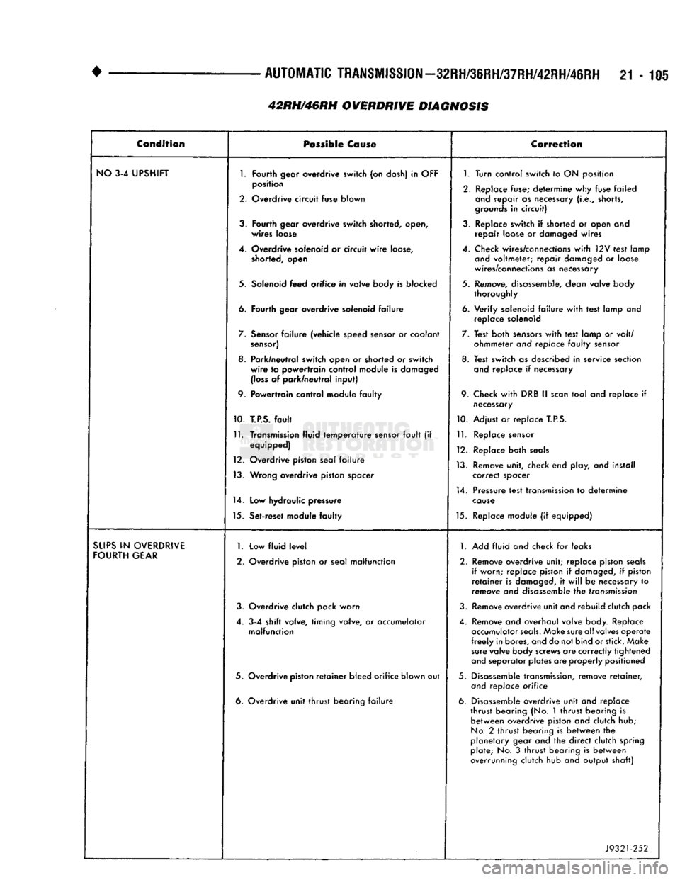
21-105 Condition
Possible
Co
use
Correction
NO
3-4 UPSHIFT
1.
Fourth
gear overdrive
switch
(on dash) in
OFF
1.
Turn control
switch
to ON position
2.
position
Overdrive
circuit
fuse
blown
2. Replace fuse; determine why fuse failed
and
repair as necessary
(i.e.,
shorts,
grounds
in
circuit)
3.
Fourth
gear
overdrive
switch
shorted, open,
wires
loose 3. Replace switch if shorted or open and
repair loose or damaged wires
4. Overdrive solenoid or circuit
wire
loose,
shorted, open 4. Check wires/connections
with
12V test lamp
and
voltmeter; repair damaged or loose
wires/connections as necessary
5. Solenoid
feed
orifice
in valve body is
blocked
5. Remove, disassemble, clean valve body
thoroughly
6.
Fourth
gear
overdrive
solenoid
failure
6. Verify solenoid
failure
with
test lamp and
replace solenoid
7.
Sensor
failure
(vehicle speed sensor or coolant
sensor)
7. Test both
sensors
with
test lamp or volt/
ohmmeter and replace
faulty
sensor
8. Park/neutral switch open or
shorted
or
switch
wire
to
powertrain
control
module is damaged
(loss
of park/neutral
input)
8. Test switch as described in service section
and
replace if necessary
9.
Powertrain
control module
faulty
9. Check
with
DRB II
scan
tool and replace if
necessary
10.
T.P.S.
fault
10. Adjust or replace
T.P.S.
11.
Transmission fluid
temperature
sensor
fault
(if equipped)
12. Overdrive piston seal
failure
13. Wrong
overdrive
piston
spacer
11.
Replace sensor
12. Replace both
seals
13. Remove unit, check end play, and install correct spacer
14.
Low
hydraulic pressure 14. Pressure test transmission to determine
cause
15. Set-reset module
faulty
15. Replace module (if equipped)
SUPS
IN
OVERDRIVE
FOURTH
GEAR
1.
2. Low
fluid
level
Overdrive piston or seal
malfunction
1.
Add fluid and check for leaks
2. Remove overdrive unit; replace piston
seals
if worn; replace piston if damaged, if piston
retainer
is damaged, it
will
be necessary to
remove and disassemble the transmission
3. Overdrive clutch pack
worn
3. Remove overdrive unit and rebuild clutch pack
4. 3-4
shift
valve,
timing
valve, or accumulator
malfunction
4. Remove and overhaul valve body. Replace
accumulator
seals.
Make sure all valves operate
freely
in bores, and do not bind or stick. Make
sure
valve body screws are correctly tightened
and
separator plates are properly positioned
5. Overdrive
piston
retainer
bleed
orifice
blown out 5. Disassemble transmission, remove
retainer,
and
replace orifice
6. Overdrive
unit
thrust
bearing
failure
6. Disassemble overdrive unit and replace
thrust bearing (No. 1 thrust bearing is between overdrive piston and clutch hub;
No.
2 thrust bearing is between the
planetary gear and the direct clutch spring plate; No. 3
thrust
bearing is between
overrunning clutch hub and output shaft)
J9321-252
42RH/46RH OVERDRIVE DIAGNOSIS
Page 1108 of 1502
+
AUTOMATIC
TRANSMISSION-32RH/36RH/37RH/42RH/46RH
21-107
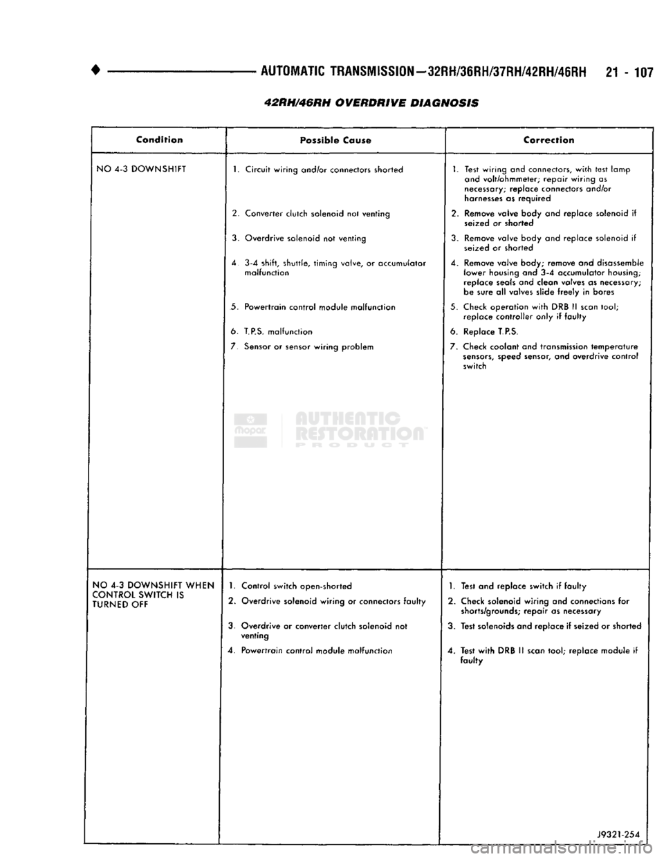
42RH/46RH
OVERDRIVE
DIAGNOSIS
Condition
Possible
Cause
Correction
NO
4-3 DOWNSHIFT 1. Circuit wiring and/or connectors shorted
2. Converter clutch solenoid not venting
3. Overdrive solenoid not venting
4.
3-4 shift, shuttle, timing
valve,
or accumulator malfunction
5. Powertrain control module malfunction
6.
T.P.S.
malfunction
7.
Sensor
or sensor wiring problem 1. Test wiring and connectors,
with
test lamp
and
volt/ohmmeter; repair wiring as
necessary;
replace connectors and/or
harnesses
as required
2. Remove valve body and replace solenoid if seized or shorted
3. Remove valve body and replace solenoid if seized or shorted
4. Remove valve body; remove and disassemble lower housing and 3-4 accumulator
housing;
replace
seals
and clean valves as necessary;
be sure all valves slide
freely
in bores
5. Check operation
with
DRB II
scan
tool; replace controller only if faulty
6. Replace
T.P.S.
7. Check coolant and transmission
temperature
sensors,
speed sensor, and overdrive control
switch
NO
4-3 DOWNSHIFT WHEN
CONTROL
SWITCH
IS
TURNED
OFF 1. Control switch open-shorted
2. Overdrive solenoid wiring or connectors faulty
3. Overdrive or converter clutch solenoid not venting
4. Powertrain control module malfunction
1.
Test and replace switch if faulty
2. Check solenoid wiring and connections for
shorts/grounds;
repair as necessary
3. Test solenoids and replace if seized or shorted
4. Test
with
DRB II
scan
tool; replace module if faulty
J9321-254
Page 1109 of 1502
21 - 108
AUTOMATIC
TRANSMISSION—32RH/36RH/37RH/42RH/46RH
•
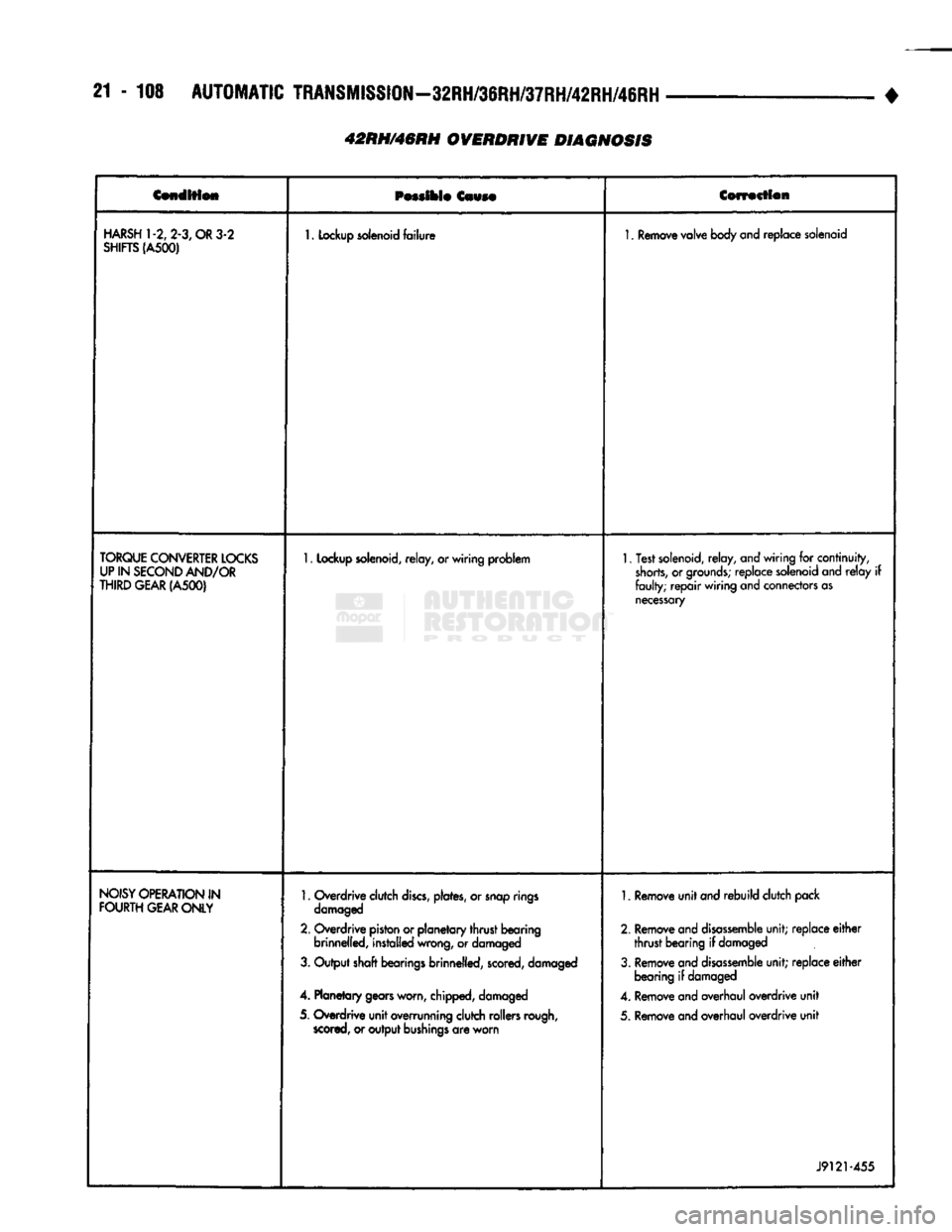
42RH/46RH OVERDRIVE DIAGNOSIS
Condition
Possible
Cause
Correction
HARSH
1-2, 2-3, OR 3-2
SHIFTS
(A500)
1.
Lockup
solenoid
failure
1.
Remove
valve
body
and
replace
solenoid
TORQUE
CONVERTER
LOCKS
UP
IN
SECOND
AND/OR
THIRD
GEAR
(A500)
1.
Lockup
solenoid,
relay, or wiring problem
1.
Test
solenoid,
relay, and wiring for continuity,
shorts,
or
grounds;
replace
solenoid
and
relay
if
faulty;
repair
wiring and
connectors
as
necessary
NOISY
OPERATION
IN
FOURTH
GEAR
ONLY
1.
Overdrive
clutch
discs,
plates,
or
snap
rings
damaged
2. Overdrive
piston
or planetary thrust bearing brinnelled,
installed
wrong,
or
damaged
3.
Output shaft
bearings
brinnelled,
scored,
damaged
4. Planetary
gears
worn,
chipped,
damaged
5. Overdrive unit
overrunning
clutch rollers
rough,
scored,
or output
bushings
are worn
1.
Remove
unit
and
rebuild
clutch
pack
2.
Remove
and
disassemble
unit; replace
either
thrust bearing if
damaged
3.
Remove
and
disassemble
unit; replace
either
bearing
if
damaged
4.
Remove
and
overhaul overdrive unit
5.
Remove
and
overhaul overdrive unit
J9121 455
Page 1483 of 1502
25
- 6
EMISSION CONTROL
SYSTEMS
•
EWAPORATIWE EMISSION CONTROLS
INDEX
page
Crankcase
Breather/Filter—Gas Powered
Engines
. . . 9
EVAP
(Evaporation)
Control
System
. 6
EVAP
Canister
. . 6
page
Evap
Canister
Purge
Solenoid
6
Fuel Tank
Filler
Tube
Cap . 7
Positive
Crankcase
Ventilation
(PCV)
System
.... 7
Pressure
Relief/Rollover Valve
6
EVAP (EVAPORATION) CONTROL SYSTEM GENERAL
INFORMATION
The function
of the
EVAP control system
is to
pre
vent
the
emissions
of
gasoline vapors from
the
fuel
tank into
the
atmosphere. When fuel evaporates
in
the fuel tank,
the
vapors pass through vent hoses
or
tubes
to a
carbon filled EVAP canister. They
are
temporarily held
in the
canister until they
can be
drawn into
the
intake manifold when
the
engine
is
running.
The vapors
are
drawn into
the
engine
at
idle
as
well
as off
idle. This system
is
called
a
Bi-level Purge
System where there
is a
dual source
of
vacuum
to re
move fuel vapor from
the
EVAP canister. The EVAP canister
is a
feature
on all
models
for
the storage
of
fuel vapors from
the
fuel tank.
The hoses used
in
this system
are
specially
manufactured.
If
replacement becomes neces sary,
it is
important
to use
only fuel resistant
hose.
PRESSURE
RELIEF/ROLLOVER VALVE
These vehicles
are
equipped with
a
combination
pressure relief
and
rollover valve. This dual function valve will relieve fuel tank pressure
and
also prevent
fuel flow through
the
fuel tank vent hoses
in the
event
of an
accidental vehicle rollover. The valve incorporates
a
pressure relief mechanism
that releases fuel tank pressure when
the
pressure increases above
the
calibrated sealing value. Refer
to
the Fuel Tank section
of
Group
14,
Fuel Systems
for
removal
and
installation procedures.
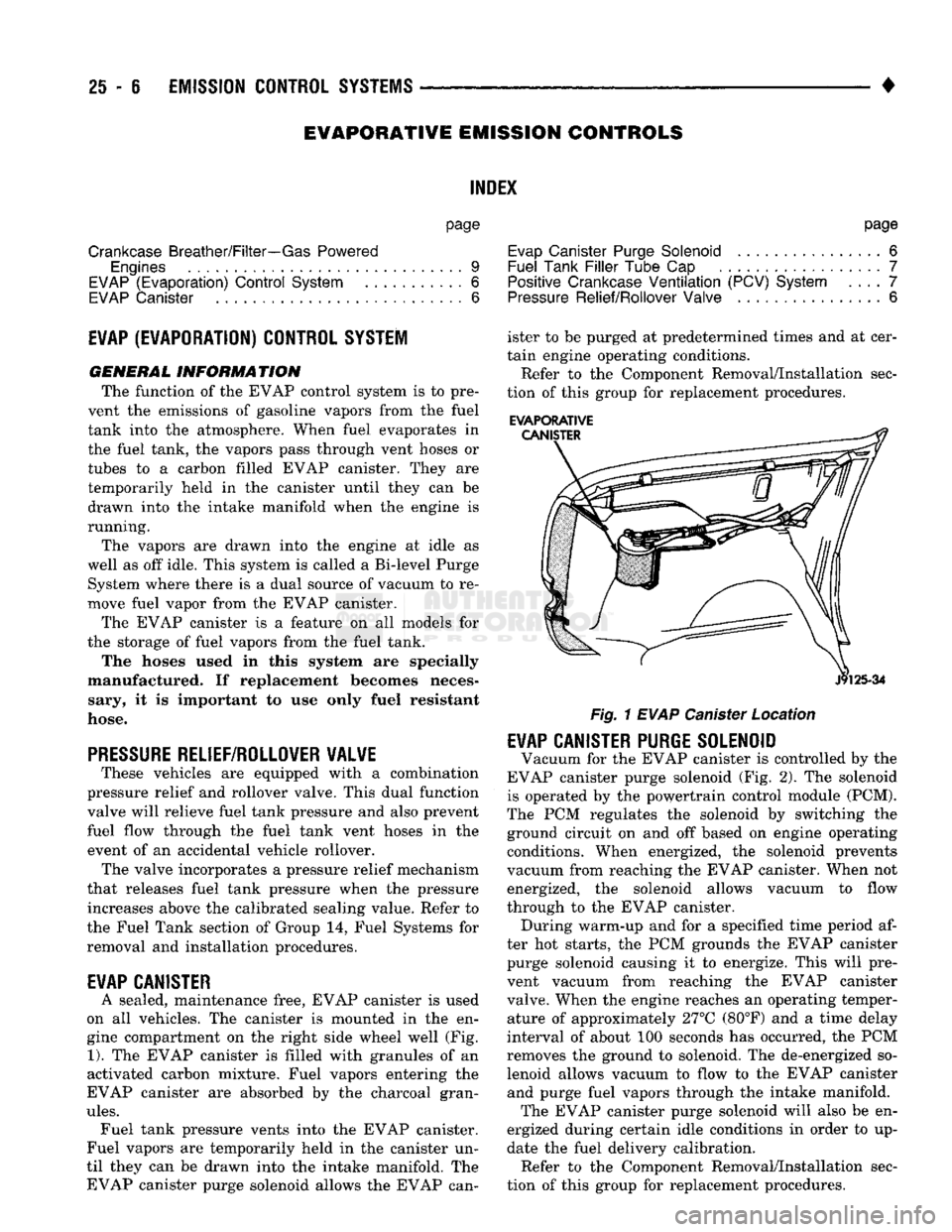
EVAP CANISTER
A sealed, maintenance free, EVAP canister
is
used
on
all
vehicles.
The
canister
is
mounted
in the en
gine compartment
on the
right side wheel well
(Fig.
1).
The
EVAP canister
is
filled with granules
of an
activated carbon mixture. Fuel vapors entering
the
EVAP canister
are
absorbed
by the
charcoal gran
ules.
Fuel tank pressure vents into
the
EVAP canister.
Fuel vapors
are
temporarily held
in the
canister
un
til they
can be
drawn into
the
intake manifold.
The
EVAP canister purge solenoid allows
the
EVAP can ister
to be
purged
at
predetermined times
and at
cer
tain engine operating conditions.
Refer
to the
Component Removal/Installation sec
tion
of
this group
for
replacement procedures.
EVAPORATIVE
Fig.
1
EVAP
Canister Location
EVAP CANISTER PURGE SOLENOID
Vacuum
for the
EVAP canister
is
controlled
by the
EVAP canister purge solenoid
(Fig. 2). The
solenoid
is operated
by the
powertrain control module (PCM).
The
PCM
regulates
the
solenoid
by
switching
the
ground circuit
on and off
based
on
engine operating conditions. When energized,
the
solenoid prevents
vacuum from reaching
the
EVAP canister. When
not
energized,
the
solenoid allows vacuum
to
flow
through
to the
EVAP canister. During warm-up
and for a
specified time period
af
ter
hot
starts,
the PCM
grounds
the
EVAP canister purge solenoid causing
it to
energize. This will pre
vent vacuum from reaching
the
EVAP canister
valve. When
the
engine reaches
an
operating temper ature
of
approximately 27°C (80°F)
and a
time delay
interval
of
about
100
seconds
has
occurred,
the PCM
removes
the
ground
to
solenoid.
The
de-energized
so
lenoid allows vacuum
to
flow
to the
EVAP canister and purge fuel vapors through
the
intake manifold. The EVAP canister purge solenoid will also
be en
ergized during certain idle conditions
in
order
to up
date
the
fuel delivery calibration. Refer
to the
Component Removal/Installation sec
tion
of
this group
for
replacement procedures.