1993 DODGE TRUCK electronic temperature cycling switch
[x] Cancel search: electronic temperature cycling switchPage 515 of 1502
8W
- 40
WIRING DIAGRAMS
Wiring Diagram Name Sheet Number
Oil-Gas
Engine
28
Temperature-Diesel Engine
. . . ., 27
Temperature-Gas Engine
. .28
Sensors
Camshaft Position
. . .20
Crankshaft Position
. .
.18,25
Engine
Coolant
Temperature
20
Electronic
Vacuum-Diesel Engine
. .34
Heated Oxygen
17
Intake
Air
Temperature
25
Map
20
Rear
Wheel Anti-Lock Brake 32,34
Throttle
Position
with
Diesel Engine
26
Vehicle Speed .20,25 Water
In
Fuel-Diesel Engine
25
Solenoids
EMCC
Solenoid
11, 12
EVAP
Purge
with
Gas
Ignition
.16
Exhaust
Gas
Recirculating
Gas Engine
.16
Fuel
.24
Transmission Overdrive
12,14
Speakers
62,64
Splices
Splice AO 1,2,4,6
Splice
A3
30,47
Splice
A4 39
Splice A21
16,23
Splice A21-1
. .68
Splice
A21-2 24
Splice A21-3
21
Splice A142
.15
Splice
A142-1 15
Splice
C4
.67,69
Splice
C7
.67,69
Splice
E2
.48,52,61,63,65
Splice F21
. , 71
Splice
F35 73
Splice
G5
12,13,14,58,77,78 Splice
G7
........... .19,25
Splice G7-1
. . .20
Splice
K4
20,26 Splice K4-1
.... ..... ; . 18,20
Splice
K6 , 20
Splice
K7 .20
Splice
L1 .79
Splice
L6 . .50
Splice
L7
43,45
Splice L7-1 40,41,47,61,63,65
Splice
L7-2
.41,79
Splice
L7-3 .41
Splice
L7-4 41
Splice
L7-5 .41
Splice
L50
......
.
........... .32,34,36,38,56
Splice
M1
49,51,52,61,63,65,75 Splice M1-1
51
Splice
M2 . .49
Splice M2-1
.51
Splice
P33 . 74
Wiring Diagram Name Sheet Number
Splice
P34 .... .74
Splice T41 ..............
.9
Splice
V6 . .
.54,55
Splice
X2 . .30
Splice X2-1
. . . .
.79,81
Splice X2-4
41
Splice X2-5
.41
Splice X2-6
.... .41
Splice X2-7
80,81
Splice X53
.65
Splice
X54
..........
. . 65
Splice Z1-1
.48
Splice Z1-2 48,52
Splice Z1-3
. . 48
Splice Z1-4
...
.44,46
Splice
Z1-5 ..... . . . .
-43,45
Splice Z1-6
11,23
Splice
Z1-7 .
.41,79
Splice Z1-8 77,78 Splice Z1-9
. .
............ .71,73,75
Splice Z1-10
. 71,73
Splice Z1-11 .77,78
Splice Z11
23
Splice
Z12 ' 17
Splice Z12-1
17,23
Steering Column Connector
.
87,88
Stereo Radio 61,63,65
Stop
Lamp Switch 32,34
Stop/Turn System
.56
Switches
A/C
Low
Pressure
with
Gas Engine
67
A/C
Low
Pressure
with
Diesel Engine
70
A/C
Heater Blower
with
Diesel Engine
69
A/C
Heater Blower
with
Gas Engine
67
A/C
Vacuum
with
Diesel Engine
69
A/C
Vacuum
with
Gas Engine
67
Automatic
Transmission
Neutral
Start
with
Diesel Engine
. .7
Automatic
Transmission
Neutral
Start
with
Gas Engine
. . .9
Back-Up
Lamp
.7,9
Brake Warning Lamp Diesel Engine
34
Brake Warning Lamp Gas Engine
. .32
Cargo
Lamp
49
Clutch
8
Clutch
Cycling
...
.68,70 Dimmer-Headlamp
47
Dome
Lamp-Front
. .50
Dome
Lamp-Rear
50
Door
Jamb
. 49
Engine
Coolant Temp
.26
Four
Wheel Drive
13
Front
Axle
13
Glove
Box
Lamp
. .52
Hazard Warning
.56
Headlamp
1,47
Heated Rear Window
39
Heater
. .
.66,67
Horn
.30
Ignition
2,10
Page 1444 of 1502
•
HEATING AND AIR CONDITIONING 24 - 7 AIR CONDITIONING SYSTEM
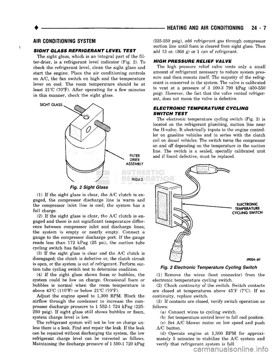
SIGHT GLASS REFRIGERANT LEWEL TEST The sight glass, which is an integral part of the fil
ter-drier, is a refrigerant level indicator (Fig. 2). To check the refrigerant level, clean the sight glass and
start the engine. Place the air conditioning controls
on A/C, the fan switch on high and the temperature lever on cool. The room temperature should be at
least 21°C (70°F). After operating for a few minutes
in this manner, check the sight glass.
SIGHT
GLASS
FILTER
DRIER
ASSEMBLY
9024-3
Fig.
2 Sight Glass
(1) If the sight glass is clear, the A/C clutch is en
gaged, the compressor discharge line is warm and
the compressor inlet line is cool; the system has a
full charge.
(2) If the sight glass is clear, the A/C clutch is en
gaged and there is not significant temperature differ
ence between compressor inlet and discharge lines;
the system is empty or nearly empty. Connect a gauge to the compressor discharge port. If the gauge
reads less than 172 kPag (25 psi), the suction tube cycling switch has failed.
(3) If the sight glass is clear and the A/C clutch is
disengaged; the clutch is defective or, the clutch circuit
is open, or the system is out of refrigerant. Perform suc
tion tube cycling switch test to determine condition.
(4) If the sight glass shows foam or bubbles, the
system could be low on charge. Occasional foam or
bubbles is normal when the room temperature is above 43°C (110°F) or below 21°C (70°F).
Adjust the engine speed to 1,300 RPM. Block the
airflow through the condenser to increase the com
pressor discharge pressure to 1 552-1 724 kPag (225- 250 psig). If sight glass still shows bubbles or foam,
system charge level is low. The refrigerant system will not be low on charge un
less there is a leak. Find and repair the leak. If the leak
can be repaired without discharging the system, the low
refrigerant charge level can be corrected as follows.
Maintaining the discharge pressure of 1 550-1 720 kPag (225-250 psig), add refrigerant gas through compressor
suction line until foam is cleared from sight glass. Then
add 13 oz. (368 g) or 1 can of refrigerant.
HIGH PRESSURE RELIEF
WALWE
The high pressure relief valve vents only a small
amount of refrigerant necessary to reduce system pres
sure and then reseats
itself.
The majority of the refrig
erant is conserved in the system. The valve is calibrated
to vent at a pressure of 3 100-3 790 kPag (450-550
psig).
However, the fact that the valve vented refriger ant, does not mean the valve is defective.
ELECTRONIC TEMPERATURE CYCLING
SWITCH TEST The electronic temperature cycling switch (Fig. 3) is
located on the refrigerant plumbing, suction line near
the H-valve. It electrically inputs to the engine control ler on gasoline vehicles and in series with the clutch
coil on diesel vehicles. The switch turns the compressor
on and off depending on the temperature in the suction
line.
The switch is a sealed, specially calibrated unit and if found defective, must be replaced.
ELECTRONIC
TEMPERATURE
CYCLING
SWITCH
J9324-97
Fig.
3 Electronic
Temperature
Cycling
Switch
(1) Remove the wires (boot connector) from the
electronic temperature cycling switch. (2) Check continuity of the switch. Switch contacts
are closed at temperatures above 45°F (7°C). If no
continuity, replace switch.
(3) If contacts are closed, verify switch operation as
follows:
(a) Connect wires to cycling switch.
(b) Set temperature control lever to full cool position. (c) Set A/C blower motor on low speed and push
A/C button.
(d) Operate engine at 1,300 RPM for approxi
mately 5 minutes to stabilize the A/C system and
verify that refrigerant system is full.
Page 1445 of 1502
24 - 8
HEATING
AND AIR
CONDITIONING
• (e) If compressor clutch cycles 3 to 10 times per
minute with temperature between 20°C-32°C (68°F-
90°F),
the cycling switch is normal. If the compressor
clutch fails to engage, check for continuity in the elec
trical circuit. Above 32°C (90°F) the compressor clutch
may be continuously engaged (non-cycling) due to the
high heat load. This condition is normal.
(4)
Refer to the Evaporator Heater Assembly for
the Removal/Installation procedures.
TESTING
THE
SYSTEM
FOR
LEAKS
If the air conditioning system is not cooling properly,
check that the refrigerant system is fully charged with
R-12.
Follow the procedures in the Sight Glass Refrig
erant Level Test section of this group.
If the refrigerant system is empty or low in refrig
erant charge, a leak at any of the line fittings or
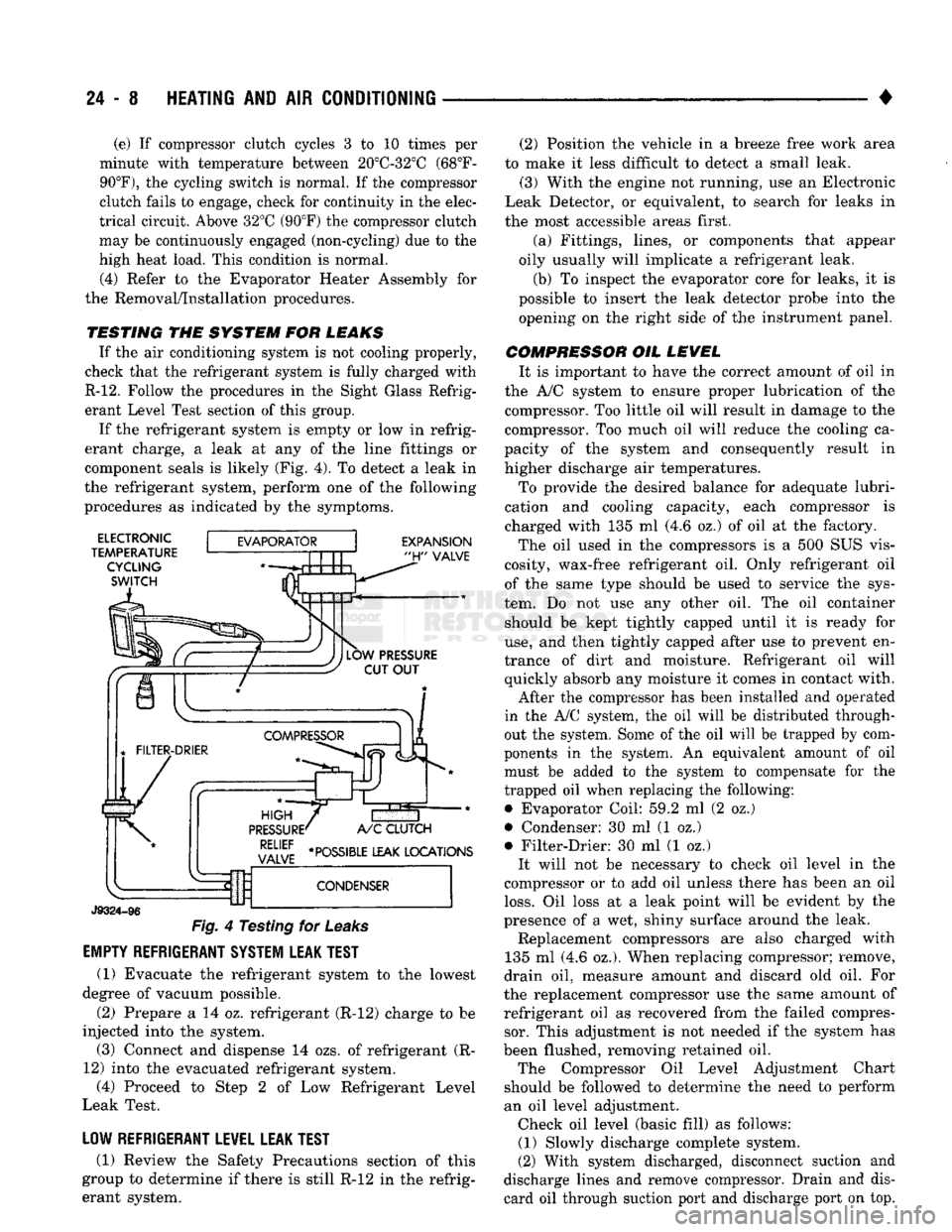
component seals is likely (Fig. 4). To detect a leak in
the refrigerant system, perform one of the following
procedures as indicated by the symptoms.
ELECTRONIC
TEMPERATURE CYCLING
SWITCH
EXPANSION
"H"
VALVE
J9324-96
Fig.
4 Testing for
Leaks
EMPTY REFRIGERANT SYSTEM LEAK TEST
(1) Evacuate the refrigerant system to the lowest
degree of vacuum possible.
(2) Prepare a 14 oz. refrigerant (R-12) charge to be
injected into the system. (3) Connect and dispense 14 ozs. of refrigerant (R-
12) into the evacuated refrigerant system, (4) Proceed to Step 2 of Low Refrigerant Level
Leak Test.
LOW REFRIGERANT LEVEL LEAK TEST
(1) Review the Safety Precautions section of this
group to determine if there is still R-12 in the refrig
erant system. (2) Position the vehicle in a breeze free work area
to make it less difficult to detect a small leak. (3) With the engine not running, use an Electronic
Leak Detector, or equivalent, to search for leaks in
the most accessible areas first.
(a) Fittings, lines, or components that appear
oily usually will implicate a refrigerant leak.
(b) To inspect the evaporator core for leaks, it is
possible to insert the leak detector probe into the opening on the right side of the instrument panel.
COMPRESSOR OIL LEVEL It is important to have the correct amount of oil in
the A/C system to ensure proper lubrication of the compressor. Too little oil will result in damage to the
compressor. Too much oil will reduce the cooling ca
pacity of the system and consequently result in
higher discharge air temperatures.
To provide the desired balance for adequate lubri
cation and cooling capacity, each compressor is
charged with 135 ml (4.6 oz.) of oil at the factory.
The oil used in the compressors is a 500 SUS vis
cosity, wax-free refrigerant oil. Only refrigerant oil of the same type should be used to service the sys
tem. Do not use any other oil. The oil container should be kept tightly capped until it is ready for
use,
and then tightly capped after use to prevent en
trance of dirt and moisture. Refrigerant oil will quickly absorb any moisture it comes in contact with.
After the compressor has been installed and operated
in the A/C system, the oil will be distributed through
out the system. Some of the oil will be trapped by com
ponents in the system. An equivalent amount of oil
must be added to the system to compensate for the
trapped oil when replacing the following: • Evaporator Coil: 59.2 ml (2 oz.)
• Condenser: 30 ml (1 oz.)
• Filter-Drier: 30 ml (1 oz.) It will not be necessary to check oil level in the
compressor or to add oil unless there has been an oil
loss.
Oil loss at a leak point will be evident by the
presence of a wet, shiny surface around the leak. Replacement compressors are also charged with
135 ml (4.6 oz.). When replacing compressor; remove,
drain oil, measure amount and discard old oil. For
the replacement compressor use the same amount of refrigerant oil as recovered from the failed compressor. This adjustment is not needed if the system has
been flushed, removing retained oil. The Compressor Oil Level Adjustment Chart
should be followed to determine the need to perform
an oil level adjustment. Check oil level (basic fill) as follows: (1) Slowly discharge complete system.
(2) With system discharged, disconnect suction and
discharge lines and remove compressor. Drain and dis card oil through suction port and discharge port on top.
Page 1449 of 1502
24-12
HEATING
AND AIR
CONDITIONING
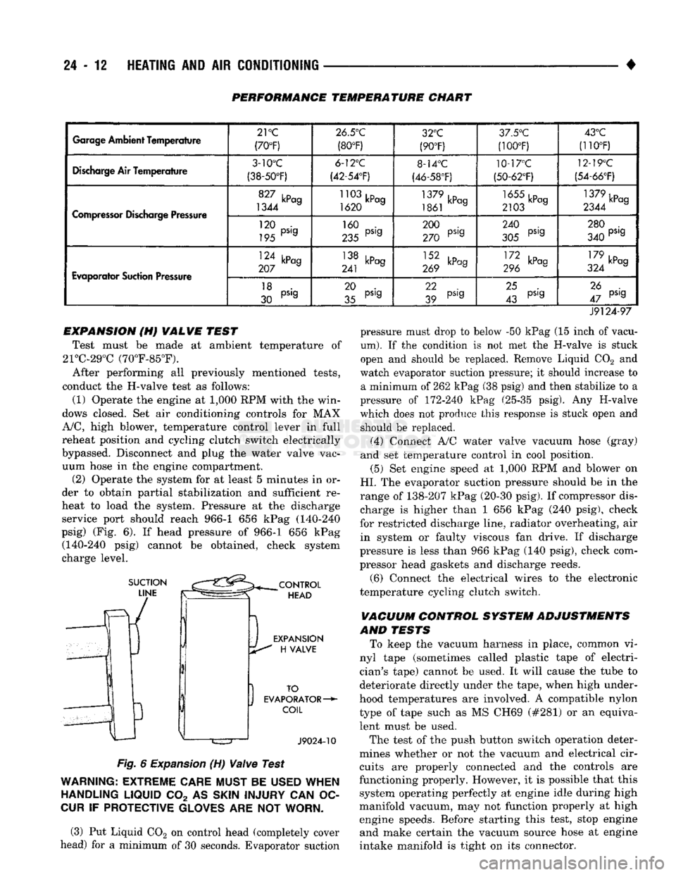
PERFORMANCE TEMPERATURE CHART
Garage
Ambient
Temperature
21
°C
(70°F) 26.5°C
(80°F) 32°C
(90°F) 3/.5°'J
(100T) 43°C
(110°F)
Discharge
Air Temperature
3-10°C
(38-50°F) 6-12°C
(42-54'F) 8-14°C
(46-58°F) 10-17°C
(50-62°F) 12-19°C
(54-66°F)
Compressor
Discharge Pressure
1344 a
1620 a
1861 kPag 2103 a 1379kPcg
2344 a
Compressor
Discharge Pressure
120 •
195 PS'9 160 .
235 PS'9 200 .
270 PS'9 240 .
305 PS'9 280 .
340 PS'9
Evaporator
Suction Pressure
124 kPag
207 a 138 kPag
241 J 269 kPag III kP°9
296 179 ,D
324 kPag
Evaporator
Suction Pressure
18 .
30 PS'9 20 .
35 pS'g 22
39 pS,g
25 .
43 pS'g 26 .
47 pS'9
J9124-97 pressure must drop to below -50 kPag (15 inch of vacu
um).
If the condition is not met the H-valve is stuck
open and should be replaced. Remove Liquid C02 and
watch evaporator suction pressure; it should increase to a minimum of 262 kPag (38 psig) and then stabilize to a
pressure of 172-240 kPag (25-35 psig). Any H-valve
which does not produce this response is stuck open and should be replaced.
(4) Connect A/C water valve vacuum hose (gray)
and set temperature control in cool position.
(5) Set engine speed at 1,000 RPM and blower on
HI.
The evaporator suction pressure should be in the
range of 138-207 kPag (20-30 psig). If compressor dis charge is higher than 1 656 kPag (240 psig), check
for restricted discharge line, radiator overheating, air in system or faulty viscous fan drive. If discharge
pressure is less than 966 kPag (140 psig), check com
pressor head gaskets and discharge reeds.
(6) Connect the electrical wires to the electronic
temperature cycling clutch switch.
VACUUM CONTROL SYSTEM ADJUSTMENTS
AND TESTS To keep the vacuum harness in place, common vi
nyl tape (sometimes called plastic tape of electri
cian's tape) cannot be used. It will cause the tube to
deteriorate directly under the tape, when high under
hood temperatures are involved. A compatible nylon type of tape such as MS CH69 (#281) or an equivalent must be used.
The test of the push button switch operation deter
mines whether or not the vacuum and electrical cir cuits are properly connected and the controls are
functioning properly. However, it is possible that this system operating perfectly at engine idle during high
manifold vacuum, may not function properly at high engine speeds. Before starting this test, stop engine and make certain the vacuum source hose at engine
intake manifold is tight on its connector.
EXPANSION (H) VALVE TEST
Test must be made at ambient temperature of
21°C-29°C (70°F-85°F).
After performing all previously mentioned tests,
conduct the H-valve test as follows:
(1) Operate the engine at 1,000 RPM with the win
dows closed. Set air conditioning controls for MAX
A/C,
high blower, temperature control lever in full
reheat position and cycling clutch switch electrically
bypassed. Disconnect and plug the water valve vac uum hose in the engine compartment. (2) Operate the system for at least 5 minutes in or
der to obtain partial stabilization and sufficient re
heat to load the system. Pressure at the discharge service port should reach 966-1 656 kPag (140-240
psig) (Fig. 6). If head pressure of 966-1 656 kPag (140-240 psig) cannot be obtained, check system
charge level.
Fig.
6
Expansion
(H)
Valve
Test
WARNING:
EXTREME
CARE
MUST
BE
USED
WHEN
HANDLING
LIQUID
C02 AS
SKIN
INJURY
CAN OC
CUR
IF
PROTECTIVE
GLOVES
ARE NOT
WORN.
(3) Put Liquid C02 on control head (completely cover
head) for a minimum of 30 seconds. Evaporator suction
Page 1457 of 1502
24
- 20
HEATING
AND AIR
CONDITIONING
• (3) Turn
3
refrigerant manifold valves completely
clockwise
to
puncture
the
cans
and
close
the
mani
fold valves.
(4) Purge
the air
from
the
charging line
by
loosen
ing
the
charging hose
at the
manifold gauge
set and
turn
one of the
refrigerant valves counterclockwise. When
the
refrigerant
gas
starts escaping from
the
loose connection, tighten
the
hose.
(5) Fully open
all 3
refrigerant manifold valves
and place
the
cans
of
refrigerant into
a pan
contain
ing 52°C (125°F) water.
The
water will warm
the
charging
can and aid in the
transfer
of the
charge
into
the
system.
(6) Start
the
engine
and
move
the
controls
to A/C
low blower position.
The electronic temperature cycling switch will pre
vent
the
clutch from engaging until refrigerant
is
added
to the
system.
If the
clutch does engage,
re
place
the
switch before proceeding
any
further. (7) Charge through
the
suction side
of the
system
by slowly opening
the
suction manifold valve. Adjust
the valve
as
necessary
so
charging pressure does
not
exceed
345
kPag
(50
psig). Maintain
the
temperature
of
the
water
in the pan by
adding warm water
as
necessary. (8) Adjust
the
engine speed
to a
fast idle
of
approx
imately
1,300 RPM.
(9) When
all 3
cans
of
refrigerant
are
completely
empty, close
the
manifold gauge
set
valves
and re
frigerant manifold valves. The maximum refrigerant charge
is 44 oz.
REFRIGERANT
LEAK REPAIR PROCEDURE
LOST CHARGE If
the
system
has
lost
all
charge
due to a
leak: (1) Evacuate
the
system.
(2) Charge
the
system with approximately
1
pound
of refrigerant. (3) Locate
all
leaks.
(4) Repair
all
leaks.
(5) Replace filter-drier bottle.
CAUTION:
Replacement
filter-drier
units
must
be
sealed
while
in
storage.
The
drier
used
in
these
units
absorbs
and
traps
moisture
quickly
upon
ex
posure
to the
atmosphere.
When
installing
a
drier,
have
all
tools
and
supplies ready
for
quick
reas
sembly
to
avoid keeping
the
system open
any
longer
than
necessary.
(6) Check system
oil
level. (7) Evacuate
and
charge
the
system.
LOW CHARGE If
the
system
has not
lost
all of its
refrigerant
charge; locate
and
repair
all
leaks.
If it is
necessary
to increase
the
system pressure
to
find
the
leak
(be
cause
of an
especially
low
charge),
add 230 g (1/2 lb)
of refrigerant.
If
there
has
been
a
significant
oil
loss,
check
the
system
oil
level.
If
leak repair
was
possible
without discharging system
and an oil
level check
was
not
necessary,
use
procedure
for
correcting
low
refrigerant level.
CORRECTING
LOW
REFRIGERANT LEVEL
Since
the
refrigeration system
is
completely sealed,
the refrigerant level will
not be low
unless there
is a
leak
in the
system. Before adding refrigerant where
the
cause
of a low
level
is not
known,
the
system should
be
tested
for
leaks.
Assuming that leaks have been corrected without
discharging
the
system, proceed with partial charge.
Install
and
connect manifold gauge
set.
(1) Close both manifold gauge
set
valves. Open
manifold gauge
set
needle valve.
(2) Connect
the
suction gauge test hose
to the
suc
tion service port
of the
compressor. Connect
the
dis charge gauge test hose
to the
discharge service port. (3) Connect
an end of
long test hose
to the
center
manifold outlet,
and
other
end to
refrigerant dispens ing manifold. (4) Close
the 2
dispensing manifold valves
and
open remaining dispensing manifold valve. Remove
protective
cap
from opened valve.
WARNING: NEVER
USE
THESE CANS
TO
CHARGE
INTO
THE
HIGH
PRESSURE SIDE
OF
THE
SYSTEM
(COMPRESSOR
DISCHARGE
PORT)
OR
INTO
A
SYSTEM
THAT
IS AT
HIGH
TEMPERATURE.
THE
HIGH
SYSTEM PRESSURES COULD
BE
TRANS
FERRED
INTO
THE
CHARGING
CAN
CAUSING
IT
TO EXPLODE.
(5) Screw
a can of R-12 to the
opened manifold
valve.
Be
sure gasket
is in
place
and in
good condi
tion. Tighten refrigerant
can and
manifold locking nut
to
ensure
a
good seal.
Do not
overtighten.
Tighten
to 9.5 N*m (7 ft. lbs.)
torque,
if
gasket
is in
good condition.
(6) Turn manifold valve (above
the
refrigerant
can)
completely clockwise
to
puncture
the can.
This closes
the valve
and
seals
the
refrigerant
in the can.
CAUTION:
Do not
heat refrigerant
12
above
52°C
(125°F).
(7) Place refrigerant
can in a
large
pan of
water
heated
to
52°C (125°F). Place
pan of
water containing
the refrigerant
can on an
accurate scale
so the
amount
of
refrigerant added
can be
weighed. Open
the refrigerant manifold valve.
(8) Purge
all air
from test hoses.
Air in the
system
will
be
trapped
in the
condenser causing abnormally
high discharge pressures
and
interfering with con densing
of the
refrigerant.
Page 1466 of 1502
HEATING
AND
AIR
CONDITIONING
24 - 29
CLIMATE CONTROL
SYSTEM
INDEX
page
Air Conditioner Distribution
and
Spot Cooler
Ducts-Center
. . 38
Air Conditioner Distribution
and
Spot Cooler
Ducts-Left Bi-Level
38
Air Conditioner Distribution
and
Spot Cooler
Ducts-Right
Bi-Level
38
Air
Outlet
Assemblies Right
Side
.............
38
Control Test
......
30
Defroster Duct
34
Electrical Controls
and
Circuits
30
Electronic Temperature Cycling Switch
37
Evaporator Control Unit
. . 34
GENERAL
INFORMATION
This
air
conditioner
is
designed specifically
for
con
ventional
cab
trucks with
the
heater-evaporator
package designed
to fit
under
the
instrument panel.
The system
is
manually controlled
by the
operator. Controls have been kept simple
for
ease
of
service and operation. In
the
blend
air
reheat
air
conditioning unit,
all
the
air
entering
the
system passes through
the
evap orator.
A
selected portion passes through
the
heater
core depending
on the
position
of the
blend
air
door.
The system controls
are
located
in the
center
of the
instrument panel within easy reach
of the
driver.
The combination electrical
and
vacuum switch con
trols
the
compressor clutch, mode
of
operation
and
blower. Modes
are Off, Max. A/C, A/C,
Vent, Heat and Defrost.
A
4-speed blower motor switch controls
the amount
of air
flow.
The
evaporator-heater pack age includes:
•
The
blower motor. • Intake duct with outside
air
recirculating door.
• Evaporator coil
• Heater core.
• Defroster discharge doors.
• Blower motor speed resistors.
• Vacuum harness.
• Vacuum actuators.
•
A/C air
outlets
to the
distribution ducts. Defrost, Heat,
A/C and
Vent modes automatically
supply
100%
outside
air.
The
air
distribution ducts supply
air
from
the
unit
to
4
panel mounted, fully directional, outlets.
The
faceplate
has 2
outlets
and 2 are
snapped into
the
panel
on the
right side. Satisfactory performance
of the air
conditioning
and heating system
is
dependent upon correct opera
tion
and
adjustment
of all
operating controls.
The in
spections, tests
and
adjustments should
be
used
to
locate
the
cause
of a
malfunction.
The
tests
in
this
page
Evaporator Heater Assembly
36
Expansion
(H)
Valve
37
Faceplate
32
General Information
. 29
Heater Assembly
. 33
Heater Control
32
Louver
Assemblies
39
Operation
of All
Controls
29
Resistor
Block
33
Temperature
and
Mode Control Cables
. 32
Vacuum
Actuators
36
Vacuum
Controls
and
Circuits
30
manual have been arranged
in a
logical sequence
that
has
proved
to be the
surest
and
shortest route
to
accurate diagnosis.
It is
recommended that they
be
followed
and
performed
in the
order they
are
pre sented.
OPERATION
OF ALL
CONTROLS
Operation must
be
tested
as
described
in the
fol
lowing sequence: (1) Inspect, test,
and
adjust compressor drive belt.
(2) Start engine
and
adjust engine speed
to 1,300
RPM.
Use a
reliable tachometer. (3) Move temperature control lever
to
Cool position
and mode lever
to A/C
position. (4)
The
inlet
air
door should
be
open
to
outside
air.
Open vehicle windows. (5) Test
the
blower operation
at all 4
speed posi
tions.
If the
blower does
not
operate correctly refer
to
Electrical Controls
and
Circuit. Leave
the
blower switch
in the
HIGH position.
(6)
The
compressor should
be
running
and the air
conditioning system
in
operation. In addition
to the six
position push button selector,
the
A/C
Heater control consists
of:
TEMPERATURE LEVER-Controls
the
tempera-.
ture
of the
discharge
air in all
modes except
MAX
A/C
and Off
when
the
vacuum operated water valve is closed. Moving
the
lever
to the
left provides cooler
air
and
moving
it to the
right provides warmer
air.
BLOWER SWITCH-The system blower
can be op
erated
at 4
speeds.
•
LOW at the
bottom. • MEDIUM
1 at the
lower center.
• MEDIUM
2 at the
upper center.
• HIGH
at the top
switch position. The blower will
be on and
operating
at the
speed
selected,
in all
push button positions except
Off.
AIR DIRECTIONAL VANES-Air
is
delivered
through
4
panel outlets.
The 4
outlets
are
adjustable
Page 1474 of 1502
•
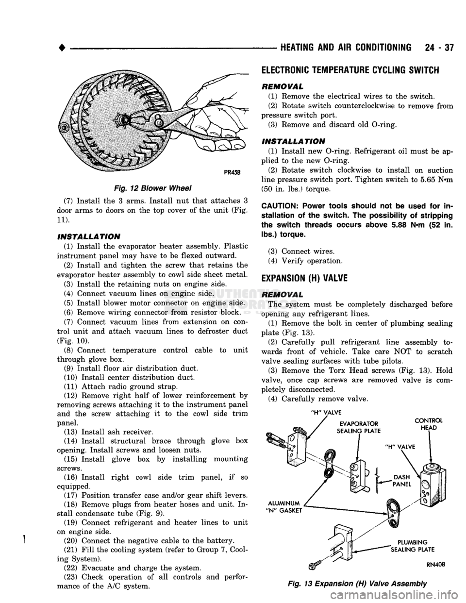
Fig.
12
Blower
Wheel
(7) Install the 3 arms. Install nut that attaches 3
door arms to doors on the top cover of the unit (Fig.
11).
INSTALLATION
(1) Install the evaporator heater assembly. Plastic
instrument panel may have to be flexed outward.
(2) Install and tighten the screw that retains the
evaporator heater assembly to cowl side sheet metal.
(3) Install the retaining nuts on engine side.
(4) Connect vacuum lines on engine side.
(5) Install blower motor connector on engine side.
(6) Remove wiring connector from resistor block.
(7) Connect vacuum lines from extension on con
trol unit and attach vacuum lines to defroster duct (Fig. 10).
(8) Connect temperature control cable to unit
through glove box. (9) Install floor air distribution duct.
(10) Install center distribution duct.
(11) Attach radio ground strap. (12) Remove right half of lower reinforcement by
removing screws attaching it to the instrument panel and the screw attaching it to the cowl side trim
panel. (13) Install ash receiver.
(14) Install structural brace through glove box
opening. Install screws and loosen nuts. (15) Install glove box by installing mounting
screws. (16) Install right cowl side trim panel, if so
equipped. (17) Position transfer case and/or gear shift levers.
(18) Remove plugs from heater hoses and unit. In
stall condensate tube (Fig. 9). (19) Connect refrigerant and heater lines to unit
on engine side.
} (20) Connect the negative cable to the battery. (21) Fill the cooling system (refer to Group 7, Cool
ing System). (22) Evacuate and charge the system.
(23) Check operation of all controls and perfor
mance of the A/C system.
HEATING
AND AIR
CONDITIONING
24 - 37
'H"
VALVE
Fig.
13
Expansion
(H)
Valve
Assembly
ELECTRONIC
TEMPERATURE
CYCLING
SWITCH
REMOVAL
(1) Remove the electrical wires to the switch.
(2) Rotate switch counterclockwise to remove from
pressure switch port. (3) Remove and discard old O-ring.
INSTALLATION
(1) Install new O-ring. Refrigerant oil must be ap
plied to the new O-ring.
(2) Rotate switch clockwise to install on suction
line pressure switch port. Tighten switch to 5.65 N#m (50 in. lbs.) torque.
CAUTION:
Power
tools
should
not be
used
for in
stallation
of the switch. The
possibility
of stripping
the
switch
threads
occurs
above
5.88 N*m (52 in.
lbs.)
torque.
(3) Connect wires. (4) Verify operation.
EXPANSION
(H)
VALVE
REMOVAL
The system must be completely discharged before
opening any refrigerant lines. (1) Remove the bolt in center of plumbing sealing
plate (Fig. 13).
(2) Carefully pull refrigerant line assembly to
wards front of vehicle. Take care NOT to scratch valve sealing surfaces with tube pilots.
(3) Remove the Torx Head screws (Fig. 13). Hold
valve, once cap screws are removed valve is com
pletely disconnected.
(4) Carefully remove valve.
Page 1475 of 1502
24
- 38
HEATING
AND AIR
CONDITIONING
INSTALLATION
(1) Remove and replace the aluminum N-gaskets
(1 on evaporator plate and 1 on plumbing plate). (2) Remove sealing cap from H-valve control head
side sealing surface and hold it against evaporator
sealing plate. DO NOT scratch sealing surface. In
stall the Torx Drive screws and tighten to 11 N-m (100 in. lbs.) torque.
(3) Remove sealing cap from plumbing side sealing
surface and hold plumbing up to valve. Install the
bolt and tighten to 23 N*m (200 in. lbs.) torque.
(4) Connect wires to electronic temperature cycling
switch. (5) After expansion valve is installed and system
charged and leak checked, repeat performance check.
AIR CONDITIONER DISTRIBUTION AND SPOT
COOLER
DUCTS-CENTER
REMOVAL (1) Disconnect the negative cable from the battery.
(2) Open glove box past stops.
(3) Remove right upper air duct by removing
mounting screw and pulling duct out through glove
box opening (Fig. 9).
(4) Remove instrument panel center brace.
(5) Remove right kick pad.
(6) Remove right instrument panel pivot bolt.
(7) Remove instrument panel cluster.
(8) Disconnect shift indicator cable.
(9) Lower steering column.
(10) Remove steering column studs.
(11) Remove radio.
(12) Remove mounting screws and remove scoop
connecting heater unit to center distribution duct. (13) Remove mounting screws and remove center
distribution duct by pulling bottom of instrument
panel out and dropping duct out (Fig. 9).
INSTALLATION
(1) Position the center distribution duct through
the bottom of instrument panel (Fig. 9). Install mounting screws.
(2) Position the scoop connecting heater unit to
center distribution duct. Install mounting screws.
(3) Install radio.
(4) Install steering column studs.
(5) Place steering column into position.
(6) Connect shift indicator cable.
(7) Install instrument panel cluster.
(8) Install right instrument panel pivot bolt.
(9) Install right kick pad.
(10) Install instrument panel center brace.
(11) Position the duct in through glove box open
ing (Fig. 9). Install mounting screw. (12) Close glove box.
(13) Connect the negative cable to the battery.
AIR CONDITIONER DISTRIBUTION AND SPOT
COOLER
DUCTS-RIGHT BI-LEVEL
REMOVAL (1) Disconnect the negative cable from the battery. (2) Open glove box past stops.
(3) Remove right upper air duct by removing
mounting screw and pulling duct out through glove
box opening (Fig. 9).
INSTALLATION
(1) Position the right upper air duct through glove
box opening (Fig. 9). Install mounting screw.
(2) Close glove box.
(3) Connect the negative cable to the battery.
AIR CONDITIONER DISTRIBUTION AND SPOT
COOLER
DUCTS-LEFT BI-LEVEL
REMOVAL
(1) Disconnect the negative cable from the battery.
(2) Remove instrument panel cluster.
(3) Disconnect shift indicator cable.
(4) Remove heater control.
(5) Remove mounting screws and cover that re
tains instrument panel wiring and let wiring hang
free.
(6) Remove mounting screw and slide left air duct
out through instrument cluster opening (Fig. 9).
INSTALLATION
(1) Slide left air duct in through instrument clus
ter opening (Fig. 9). Install mounting screw. (2) Position the cover that retains instrument
panel wiring. Install mounting screws.
(3) Install heater control.
(4) Connect shift indicator cable.
(5) Install instrument panel cluster.
(6) Connect the negative cable to the battery.
AIR OUTLET
ASSEMBLIES
RIGHT
SIDE
Both right side outlets are held in place with
spring loaded retaining clips.
REMOVAL (1) With outlet facing out and louver vanes open,
grasp adjusting vane with fingers.
(2) Pull smoothly and firmly to unseat clips and
complete removal toward rear of vehicle.
INSTALLATION
(1) Position outlet assembly in panel opening, f
making sure lettering stamped TOP is up (ribs on
housing match notches on instrument panel).
(2) Press housing assembly until both retaining
clips lock into place.