1993 DODGE TRUCK spare tire
[x] Cancel search: spare tirePage 30 of 1502

LUBRICATION
AND
MAINTENANCE
0-11
J
DRIVE-ON
HOIST
I
FRAME
CONTACT
HOIST
TWIN
POST
CHASSIS
HOIST
FLOOR
JACK
RROOD30
Fig.
8 Correct Vehicle Lifting
Locations
An axle tube
A body side sill
A steering linkage component
A drive shaft
The engine or transmission oil pan
The fuel tank
• A front suspension arm Use the correct frame rail lifting locations only
(Fig. 8).
HOIST A vehicle can be lifted with:
• A single-post, frame-contact hoist
• A twin-post, chassis hoist
• A ramp-type, drive-on hoist
When a frame-contact type hoist is used, verify
that the lifting pads are positioned properly (Fig. 8).
WARNING:
WHEN
A
SERVICE
PROCEDURE
RE
QUIRES
THE
REMOVAL
OF
THE
REAR
AXLE,
FUEL
TANK,
OR
SPARE
TIRE,
EITHER:
• PLACE ADDITIONAL WEIGHT ON THE REAR
END OF THE VEHICLE
« ATTACH THE VEHICLE TO THE HOIST
« PLACE JACK STANDS UNDER THE VEHICLE
FOR SUPPORT TO PREVENT TIPPING WHEN
THE CENTER OF BALANCE CHANGES
4WD VEHICLES A standard hoist can be used to lift a 4WD vehicle.
The hoist should be inspected for adequate clearance. The lift arms, pads or ramps should be adjusted to
ensure that there is adequate clearance (Fig. 9).
ADJUSTMENT
PAD
ii 7
MAINTAIN
CLEARANCE
HOIST
ARM
RK44
Fig.
9 Lifting 4WD Vehicle
With
Single-Post
Hoist—
Typical
When a twin-post hoist is used, a 4 x 4 x 12-inch
wood spacer also could be required. Place the wood spacer under the front axle (opposite the differential
housing). This will maintain balance and level lift ing.
CAUTION:
The
block
that
is
used must
be
secured in
a
safe manner. This
will
ensure
that
it
will
not un
balance
the
vehicle.
VEHICLE
TOWING
RECOMMENDATIONS
When it is necessary to tow a Ram Truck, the rec
ommended method is either:
• the sling-type, rear-end raised towing method; or
• the wheel-lift towing method with a tow dolly lo
cated under the front wheels. A vehicle with flat-bed hauling equipment can also
be used to transport a disabled vehicle.
SLING-TYPE
FLAT
BED
RR0OD29
Fig.
10 Tow Vehicles
With
Approved
Equipment
Page 817 of 1502
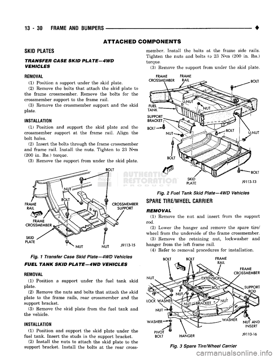
13
- 30 FRAME AND BUMPERS
ATTACHED COMPONENTS
SKID
PLATES
TRANSFER CASE SKID
PL
ATF
4 WD
VEHICLES
REMOVAL
(1) Position
a
support under
the
skid plate.
(2) Remove
the
bolts that attach
the
skid plate
to
the frame crossmember. Remove
the
bolts
for the
crossmember support
to the
frame rail.
(3) Remove
the
crossmember support
and the
skid
plate.
INSTALLATION
(1) Position
and
support
the
skid plate
and the
crossmember support
at the
frame rail. Align
the
bolt holes.
(2) Insert
the
bolts through
the
frame crossmember
and frame rail. Install
the
nuts. Tighten
to 23 N*m
(200
in. lbs.)
torque.
(3) Remove
the
support from under
the
skid plate.
Fig.
1
Transfer
Case Skid
Plate—4WD Vehicles
FUEL TANK SKID
PLATE-4WD
VEHICLES
REMOVAL
(1) Position
a
support under
the
fuel tank skid
plate.
(2) Remove
the
nuts
and
bolts that attach
the
skid
plate
to the
frame rails, rear crossmember
and the
support bracket.
(3) Remove
the
skid plate from
the
fuel tank
and
the vehicle.
INSTALLATION
(1) Position
and
support
the
skid plate under
the
fuel tank. Insert
the
studs
in the
support bracket.
(2) Install
the
nuts
to
attach
the
skid plate
to the
support bracket. Install
the
bolts
at the
rear cross- member. Install
the
bolts
at the
frame side rails.
Tighten
the
nuts
and
bolts
to 23 N*m (200 in. lbs.)
torque.
(3) Remove
the
support from under
the
skid plate.
FRAME FRAME
Fig.
2
Fuel
Tank
Skid
Plate-4WD Vehicles
SPARE
TIRE/WHEEL
CARRIER
REMOVAL
(1) Remove
the nut and
insert from
the
support
rod. (2) Lower
the
hanger
and
remove
the
spare tire/
wheel from
the
underside
of the
frame crossmember.
(3) Remove
the
retaining
nut,
lockwasher
and
hanger from
the
left frame rail.
(4) Refer
to
removal procedures
for
installation. BOLT BOLT FRAME
Fig.
3
Spare
The/Wheel Carrier
Page 818 of 1502
1
•
FRAME
AND
BUMPERS
13 - 31 PIVOT BOL T ADJUSTMENT
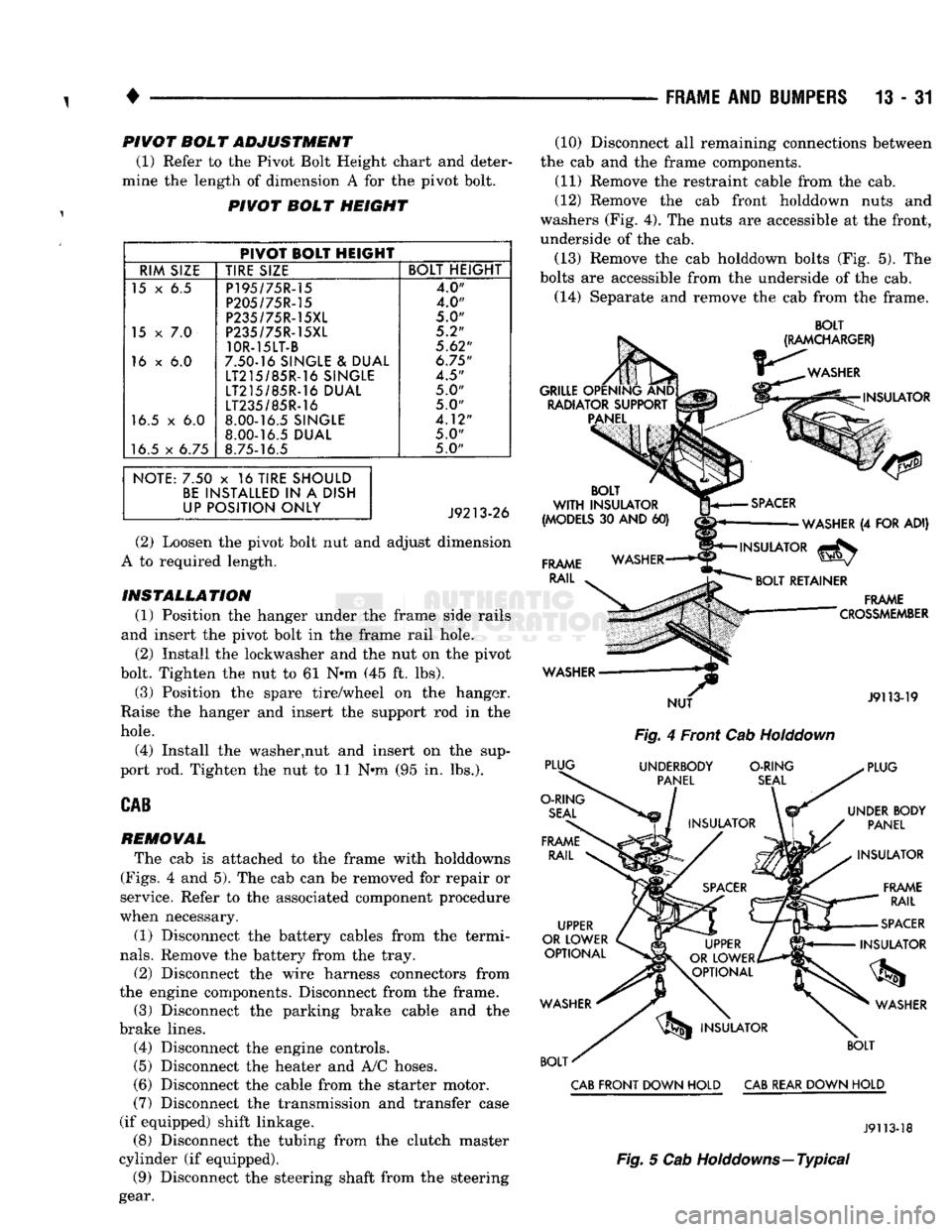
(1) Refer to the Pivot Bolt Height chart and deter
mine the length of dimension A for the pivot bolt.
PIVOT BOLT HEIGHT
PIVOT BOLT HEIGHT
RIM SIZE TIRE SIZE BOLT HEIGHT
15 x 6.5 P195/75R-15
4.0"
P205/75R-15 4.0"
P235/75R-15XL
5.0"
15
x 7.0
P235/75R-15XL 5.2"
10R-15LT-B
5.62"
16 x 6.0 7.50-16 SINGLE & DUAL
6.75"
LT215/85R-16 SINGLE
4.5"
LT215/85R-16 DUAL 5.0"
LT235/85R-16
5.0"
16.5 x 6.0 8.00-16.5 SINGLE
4.12"
8.00-16.5 DUAL
5.0"
16.5 x 6.75 8.75-16.5 5.0"
NOTE: 7.50 x 16 TIRE SHOULD BE INSTALLED IN A DISH
UP POSITION ONLY
(2) Loosen the pivot bolt nut and adjust dimension
A to required length.
INSTALLATION (1) Position the hanger under the frame side rails
and insert the pivot bolt in the frame rail hole. (2) Install the lockwasher and the nut on the pivot
bolt. Tighten the nut to 61 N*m (45 ft. lbs).
(3) Position the spare tire/wheel on the hanger.
Raise the hanger and insert the support rod in the
hole.
(4) Install the washer,nut and insert on the sup
port rod. Tighten the nut to 11 Nnn (95 in. lbs.).
CAB
REMOVAL
The cab is attached to the frame with holddowns
(Figs.
4 and 5). The cab can be removed for repair or
service. Refer to the associated component procedure
when necessary.
(1) Disconnect the battery cables from the termi
nals.
Remove the battery from the tray.
(2) Disconnect the wire harness connectors from
the engine components. Disconnect from the frame. (3) Disconnect the parking brake cable and the
brake lines. (4) Disconnect the engine controls.
(5)
Disconnect the heater and A/C hoses.
(6) Disconnect the cable from the starter motor.
(7)
Disconnect the transmission and transfer case
(if equipped) shift linkage. (8) Disconnect the tubing from the clutch master
cylinder (if equipped). (9) Disconnect the steering shaft from the steering
gear. (10) Disconnect all remaining connections between
the cab and the frame components. (11) Remove the restraint cable from the cab.
(12) Remove the cab front holddown nuts and
washers (Fig. 4). The nuts are accessible at the front,
underside of the cab.
(13) Remove the cab holddown bolts (Fig. 5). The
bolts are accessible from the underside of the cab.
(14) Separate and remove the cab from the frame.
BOLT
Fig.
4 Front Cab
Holddown
CAB
FRONT DOWN HOLD
CAB
REAR DOWN HOLD
J9113-18
Fig.
5 Cab Holddowns—Typical
Page 1104 of 1502
•
AUTOMATIC
TRANSMISSION—32RH/36RH/37RH/42RH/46RH
21-103
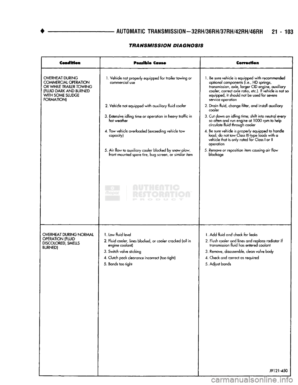
TRANSMISSION DIAGNOSIS
Condition
Possible
Couso
Correction
OVERHEAT
DURING
COMMERCIAL
OPERATION
OR
WHILE
TRAILER
TOWING
(FLUID
DARK
AND
BURNED
WITH
SOME
SLUDGE
FORMATION)
1.
Vehicle not properly equipped for
trailer
towing or
commercial use
2. Vehicle not equipped
with
auxiliary fluid cooler
3.
Extensive idling
time
or operation in heavy
traffic
in hot weather
4. Tow vehicle overloaded (exceeding vehicle tow capacity)
5. Air flow to auxiliary cooler blocked by snow plow,
front
mounted spare
tire,
bug screen, or similar
item
1.
Be sure vehicle is equipped
with
recommended
optional components
(i.e.,
HD
springs,
transmission,
axle, larger CID engine, auxiliary cooler, correct axle ratio, etc.). If vehicle is not so
equipped, it should not be used for severe
service operation
2. Drain fluid, change
filter,
and install auxiliary cooler
3.
Cut down on idling time; shift into
neutral
every
so
often and run engine at 1000 rpm to help
circulate fluid through cooler
4. Be sure vehicle is properly equipped to handle
load;
do not tow
Class
Ill-type loads
with
a
vehicle
that
is only
rated
for
Class
1
or II operation
5.
Remove or reposition
item
causing
air flow
blockage
OVERHEAT
DURING
NORMAL
OPERATION
(FLUID
DISCOLORED,
SMELLS
BURNED)
1.
Low
fluid
level
2. Fluid cooler, lines blocked, or cooler cracked (oil in engine coolant)
3.
Switch valve sticking
4. Clutch pack clearance incorrect (too tight)
5.
Bands
too tight 1. Add
fluid
and check for leaks
2. Flush cooler and lines and replace radiator if
transmission
fluid has
entered
coolant
3.
Remove,
disassemble,
clean valve body
4. Check and correct as required
5. Adjust bands
J9121-450
Page 1370 of 1502
•
WHEELS
AND
TIRES
22 - 1
CONTENTS
page page
TIRES
1
VEHICLE VIBRATION
11
TORQUE SPECIFICATIONS
13
WHEELS
6
TIRES INDEX
page
Cleaning
of
Tires
2
General
Information
1
Pressure
Gauges
. 2
Repairing Leaks
3
Replacement Tires
2
GENERAL
INFORMATION
Tires are designed for each specific vehicle. They
provide the best overall performance for normal op eration. The ride and handling characteristics match
the vehicle's requirements. With proper care they
will give excellent reliability, traction, skid resis
tance, and tread life. These tires have specific load carrying capacities. When correctly inflated, they
will operate properly.
Tires used in cool climates, and with light loads
will have a longer life than tires used in hot climates
with heavy loads. Abrasive road surfaces will accel erate tire wear.
Driving habits have more effect on tire life than
any other factor. Careful drivers will obtain much
greater mileage than careless drivers.
Driving habits that shorten the life of any tire;
• Rapid acceleration and deceleration
• Severe application of brakes • High-speed driving
• Taking turns at excessive speeds
• Striking curbs and other obstacles It is very important to follow the tire rotation in
terval
IDENTIFICATION Tire type, size, aspect ratio and speed rating are
encoded in the letters and numbers imprinted on the
side wall of the tire. Refer to the chart to decipher
the tire identification code (Fig. 1). Performance tires will have a speed rating letter
after the aspect ratio number. The speed rating is
page
Rotation
. 3
Tire
Inflation
Pressures
2
Tire
Noise
or
Vibration
4
Tire
Wear
Patterns
4
Tread Wear
Indicators
3
not always printed on the tire side wall. The letter S
indicates that the tire is speed rated up to 112 mph.
• Q up to 100 mph
• T up to 118 mph
• U up to 124 mph
• H up to 130 mph
• V up to 149 mph
• Z more than 149 mph (consult the tire manufac
turer for the specific speed rating)
An All Season type tire will have either M + S, M
& S or M—S (indicating mud and snow traction) im
printed on the side wall.
RADIAL-PLY TIRES Radial-ply tires improve handling, tread life, ride
quality and decrease rolling resistance. Radial-ply tires must always be used in sets of
four. Under no circumstances should they be used on
the front only. They may be mixed with temporary spare tires when necessary, but reduced speeds are
recommended.
Radial-ply tires have the same load-carrying capac
ity as other types of tires of the same size. They use
the same recommended inflation pressures.
SPARE TIRE (TEMPORARY) The compact spare tire is designed for emergency
use only. The original tire should be repaired and re
installed at the first opportunity. Refer to Owner's
Manual for complete details.
WHEELS
AND
TIRES
Page 1418 of 1502
•
BODY
COMPONENTS
23 - 35
CAB/BODY
INTERIOR COMPONENTS
INDEX
page
Carpets
and
Floor Mats
51
Floor Console
and
Rear Storage Tray
.........
50
Front Seats
38
Headliners
48
Instrument
Panel
35
page
Interior
Trim
Panels
. 42
Rear
Seats
41
Shoulder
Belts/Lap Belt/Buckles
45
Spare
Tire
Carrier
45
INSTRUMENT
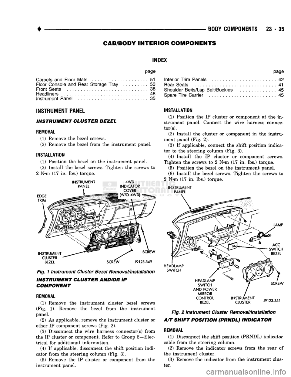
PANEL INSTRUMENT CLUSTER BEZEL
REMOVAL
(1) Remove
the
bezel screws.
(2) Remove
the
bezel from
the
instrument panel.
INSTALLATION
(1) Position
the
bezel
on the
instrument panel.
(2) Install
the
bezel screws. Tighten
the
screws
to
2
Nnn (17 in. lbs.)
torque.
INSTRUMENT
PANEL
EDGE
TRIM
4WD
INDICATOR COVER 4WD)
INSTRUMENT CLUSTER
BEZEL
SCREW
Fig.
11nstrument
Cluster
Bezel
Removal/Installation
INSTRUMENT CLUSTER AND/OR
IP
COMPONENT
REMOVAL
(1) Remove
the
instrument cluster bezel screws
(Fig.
1).
Remove
the
bezel from
the
instrument
panel.
(2)
As
applicable, remove
the
instrument cluster
or
other
IP
component screws
(Fig. 2).
(3) Disconnect
the
wire harness connector(s) from
the
IP
cluster
or
component. Refer
to
Group 8—Elec
trical
for
additional information. (4)
If
applicable, disconnect
the
shift position indi
cator from
the
steering column
(Fig. 3).
(5) Remove
the IP
cluster
or
component from
the
instrument panel.
INSTALLATION
(1) Position
the IP
cluster
or
component
at the in
strument panel. Connect
the
wire harness connec
tors).
(2) Install
the
cluster
or
component
in the
instru
ment panel
(Fig. 2).
(3)
If
applicable, connect
the
shift position indica
tor
to the
steering column
(Fig. 3).
(4) Install
the IP
cluster
or
component screws.
Tighten
the
screws
to 2 N#m (17 in. lbs.)
torque. (5) Position
the
bezel
on the
instrument panel.
(6) Install
the
bezel screws. Tighten
the
screws
to
2
Nnn (17 in. lbs.)
torque.
INSTRUMENT
PANEL
LAMP
ACC
SWITCH
BEZEL
HEADLAMP SWITCH
HEADLAMP SWITCH
AND POWER MIRROR
CONTROL
BEZEL
SCREW
INSTRUMENT
J9123351
CLUSTER
J9123-351
Fig.
2
Instrument
Cluster
Removal/Installation
A/T SHIFT POSITION (PRNDL) INDICATOR
REMOVAL
(1) Disconnect
the
shift position (PRNDL) indicator
cable from
the
steering column.
(2) Remove
the
indicator screws from
the
rear
of
the instrument cluster. (3) Remove
the
indicator from
the
instrument clus
ter.
Page 1427 of 1502
23
- 44
BODY
COMPONENTS
•
CAB
REAR
CORNER/QUARTER
WINDOW
AND
REAR
WINDOW
UPPER/LOWER
TRIM
PANELS
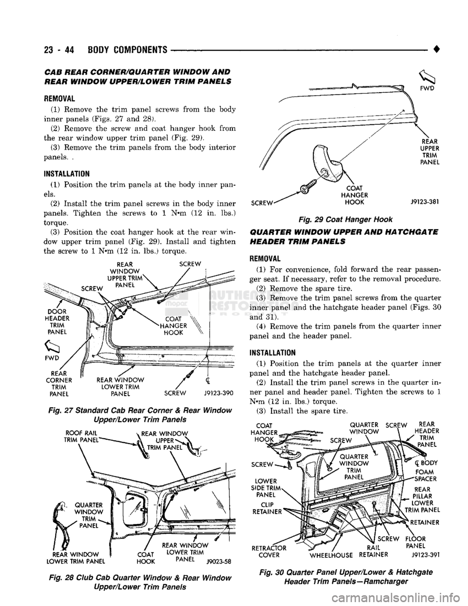
REMOVAL
(1) Remove
the
trim panel screws from
the
body
inner panels (Figs.
27 and 28).
(2) Remove
the
screw
and
coat hanger hook from
the rear window upper trim panel
(Fig. 29).
(3) Remove
the
trim panels from
the
body interior
panels.
.
INSTALLATION
(1) Position
the
trim panels
at the
body inner pan
els.
(2) Install
the
trim panel screws
in the
body inner
panels. Tighten
the
screws
to 1 N»m (12 in. lbs.)
torque.
(3) Position
the
coat hanger hook
at the
rear win
dow upper trim panel
(Fig. 29).
Install
and
tighten
the screw
to 1 Nem (12 in. lbs.)
torque.
REAR
WINDOW
UPPER
TRIM
PANEL
SCREW
REAR
CORNER
TRIM
PANEL
REAR
WINDOW
LOWER
TRIM
PANEL
SCREW
J9123-390
Fig.
27
Standard Cab Rear Corner
&
Rear Window
Upper/Lower
Trim
Panels
ROOF
RAIL
TRIM
PANEL'
k
REAR
WINDOW
UPPER*
k TRIM
PANEL
REAR
WINDOW
LOWER
TRIM
PANEL
QUARTER
WINDOW
TRIM
PANEL
COAT
HOOK
REAR
WINDOW
LOWER
TRIM
PANEL
J9023-58
Fig.
28
Club
Cab
Quarter
Window
&
Rear Window
Upper/Lower
Trim
Panels
SCREW
COAT
HANGER
HOOK
REAR
UPPER
TRIM
PANEL
J9123-381
Fig.
29
Coat Hanger
Hook
QUARTER
WINDOW
UPPER
AND
HATCHGATE
HEADER
TRIM
PANELS
REMOVAL
(1)
For
convenience, fold forward
the
rear passen
ger seat.
If
necessary, refer
to the
removal procedure.
(2) Remove
the
spare tire.
(3) Remove
the
trim panel screws from
the
quarter
inner panel
and the
hatchgate header panel (Figs.
30
and
31).
(4) Remove
the
trim panels from
the
quarter inner
panel
and the
header panel.
INSTALLATION
(1) Position
the
trim panels
at the
quarter inner
panel
and the
hatchgate header panel.
(2) Install
the
trim panel screws
in the
quarter
in
ner panel
and
header panel. Tighten
the
screws
to 1
N*m
(12 in. lbs.)
torque.
(3) Install
the
spare tire.
COAT
HANGER
HOOK
SCREW
LOWER
SIDE
TRIM
PANEL
CLIP
RETAINER
RETRACTOR
COVER
QUARTER
SCREW
WINDOW
SCREW
REAR
HEADER
TRIM
PANEL
([BODY
FOAM
SPACER
REAR
PILLAR
LOWER
TRIM
PANEL
RETAINER
SCREW
FLOOR
RAIL
PANEL
WHEELHOUSE
RETAINER
J9123-391
Fig.
30
Quarter
Panel Upper/Lower
&
Hatchgate
Header
Trim
Panels—Ramcharger
Page 1428 of 1502
•
BODY
COMPONENTS 23 - 45
LOWER
SIDE TRIM PANEL
QUARTER
WINDOW
TRIM
PANEL
ROOF
INNER PANEL
\C SCREW
QUARTER PANEL SCREW
QUARTER WINDOW QUARTER WINDOW TRIM
PANEL
TRIM
PANEL
LOWER SECTION UPPER SECTION
SCREW
ASH
RECEIVER BEZEL
ASH RECEIVER LOWER SIDE TRIM PANEL CLIP
RETAINER LOWER
SIDE TRIM PANEL ROOF
INNER PANEL
RETAINER RAIL LOWER SIDE
TRIM PANEL
AT FLOOR PANEL SCREW REAR
HEADER TRIM
PANEL
ABOVE HATCHGATE
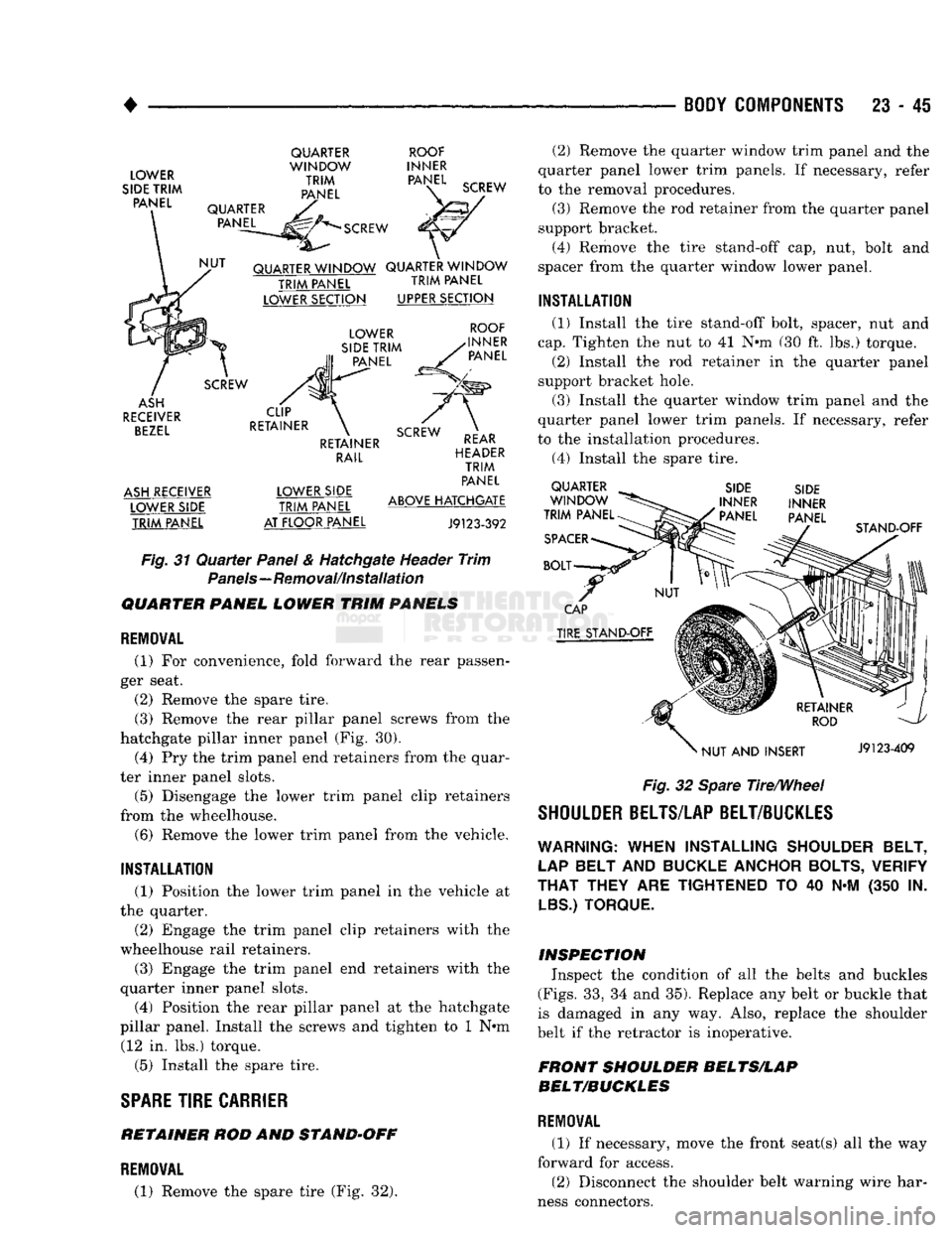
J9123-392 Fig.
31
Quarter
Panel & Hatchgate Header
Trim
Panels—Removal/Installation
QUARTER PANEL LOWER TRIM PANELS
REMOVAL
(1)
For
convenience, fold forward
the
rear passen
ger seat.
(2) Remove
the
spare tire. (3) Remove
the
rear pillar panel screws from
the
hatchgate pillar inner panel
(Fig. 30).
(4)
Pry the
trim panel end retainers from
the
quar
ter inner panel slots.
(5) Disengage
the
lower trim panel clip retainers
from
the
wheelhouse. (6) Remove
the
lower trim panel from
the
vehicle.
INSTALLATION
(1) Position
the
lower trim panel
in the
vehicle
at
the quarter.
(2) Engage
the
trim panel clip retainers with
the
wheelhouse rail retainers.
(3) Engage
the
trim panel
end
retainers with
the
quarter inner panel slots.
(4) Position
the
rear pillar panel
at the
hatchgate
pillar panel. Install
the
screws
and
tighten
to 1 N»m
(12
in. lbs.)
torque.
(5) Install
the
spare tire.
SPARE
TIRE
CARRIER
RETAINER
ROD AND
STAND-OFF
(2)
Remove
the
quarter window trim panel
and the
quarter panel lower trim panels.
If
necessary, refer
to
the
removal procedures. (3) Remove
the
rod retainer from
the
quarter panel
support bracket. (4) Remove
the
tire stand-off
cap, nut,
bolt
and
spacer from
the
quarter window lower panel.
INSTALLATION
(1) Install
the
tire stand-off bolt, spacer,
nut and
cap.
Tighten
the nut to 41 N»m (30 ft. lbs.)
torque.
(2) Install
the rod
retainer
in the
quarter panel
support bracket hole.
(3) Install
the
quarter window trim panel
and the
quarter panel lower trim panels.
If
necessary, refer
to
the
installation procedures.
(4)
Install
the
spare tire. QUARTER
WINDOW
TRIM PANEL
SPACER
BOLT SIDE
INNER
' PANEL SIDE
INNER
PANEL STAND-OFF
CAP
TIRE STAND-OFF
NUT
AND
INSERT J9123-409
Fig.
32 Spare Tire/Wheel
SHOULDER BELTS/LAP BELT/BUCKLES
WARNING:
WHEN
INSTALLING
SHOULDER BELT,
LAP
BELT
AND
BUCKLE ANCHOR BOLTS, VERIFY
THAT
THEY
ARE
TIGHTENED
TO 40 N-M (350 IN.
LBS.) TORQUE.
INSPECTION Inspect
the
condition
of all the
belts
and
buckles
(Figs.
33, 34 and
35). Replace
any
belt
or
buckle that
is damaged
in any way.
Also, replace
the
shoulder
belt
if
the retractor
is
inoperative.
FRONT SHOULDER BELTS/LAP
BELT/BUCKLES
REMOVAL
(1)
If
necessary, move
the
front seat(s)
all the way
forward
for
access. (2) Disconnect
the
shoulder belt warning wire har
ness connectors.
REMOVAL
(1) Remove
the
spare tire
(Fig. 32).