1993 DODGE TRUCK CD changer
[x] Cancel search: CD changerPage 279 of 1502

7 - 8
COOLING
SYSTEM
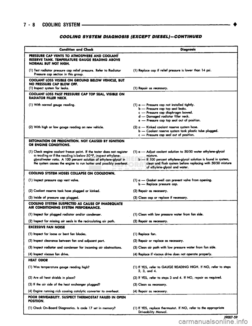
COOLING SYSTEM DIAGNOSIS (EXCEPT DIESEL)—CONTINUED
Condition and Check
Diagnosis
PRESSURE
CAP
VENTS
TO
ATMOSPHERE
AND COOLANT
RESERVE
TANK.
TEMPERATURE
GAUGE
READING
ABOVE
NORMAL
BUT NOT HIGH.
(1) Test radiator pressure cap
relief
pressure. Refer to Radiator Pressure cap section in this group. (1) Replace cap if
relief
pressure is lower than 14 psi.
COOLANT
LOSS
VISIBLE
ON
GROUND
BELOW
VEHICLE,
BUT
NO
PRESSURE
CAP
BLOW
OFF.
(1) Inspect
system
for leaks. (1) Repair as necessary.
COOLANT
LOSS
PAST
PRESSURE
CAP
TOP
SEAL,
VISIBLE
ON
RADIATOR
FILLER
NECK.
(1) With normal gauge reading. (1) a — Pressure cap not installed tightly.
b — Pressure cap top seal leaks.
c
— Pressure cap diaphragm bowed.
d — Damaged radiator
filler
neck.
e — Pressure cap top seal out of position.
(2) With high or low gauge reading on new vehicle. (2) a — Kinked coolant reserve
system
hose.
b — Coolant reserve
system
tank
plastic
tube
plugged,
c
— Pressure cap seal out of position.
DETONATION
OR
PREIGNITION.
NOT
CAUSED
BY IGNITION
OR
ENGINE
CONDITIONS.
(1) Check engine coolant
freeze
point. If the
tester
does
not register a reading or if
the
reading
is
below
50°F,
inspect
ethylene-
glycol/water
ratio.
A 100
percent
solution of ethylene-glycol in
the
system
causes
the engine to run
hotter
and
possibly
overheat. (1) a — Adjust coolant solution to
50/50
water
ethylene-glycol
mixture.
b — If 100
percent
ethylene-glycol solution
is
found in system, clean and flush
system
before
replacing
with
50/50
mixture
of ethylene-glycol and
water.
COOLING
SYSTEM
HOSES
COLLAPSE
ON
COOLDOWN.
(1) Inspect pressure cap
vent
valve. (1) a — Gasket swell can
prevent
valve from opening,
b — Replace pressure cap.
(2) Coolant reserve
tank
hose plugged or kinked. (2) Repair as necessary.
(3) Inside of pressure cap plugged. (3) Clean cap or replace if necessary.
COOLING
SYSTEM
SUSPECTED
AS
CAUSE
OF
INADEQUATE
AIR
CONDITIONING
SYSTEM
PERFORMANCE.
(1) Inspect for plugged radiator and/or condenser. (1) Clean
with
low pressure
water
from fan side.
(2) Inspect for
missing
air
seals
in the recirculating air path. (2) Repair as necessary.
EXCESSIVE
FAN
NOISE
(1) Inspect for loose or
bent
fan blades. (1) Replace fan.
(2) Inspect clearance
between
fan and adjacent
part.
(2) Repair or replace as necessary.
(3) Inspect radiator and condenser for incoming air obstructions. (3) Clean air path
with
low pressure
water
from fan side.
(4) Inspect
viscous
fan drive. (4) Replace if
viscous
drive
does not
operate
properly.
HEAT
ODOR
(1) Was
temperature
gauge reading
high?
(1) If
YES,
refer
to
GAUGE
READING
HIGH. If NO,
refer
to steps
2, 3, and 4.
(2) Are all
heat
shields in place? (2) If
YES,
refer
to
steps
3 and 4. If NO,
repair
as required.
(3) If the air side of the
heat
exchanger
plugged?
(3) Clean as necessary.
(4) Engine running rich
causing
catalytic converter to overheat. (4) Repair as necessary.
POOR
DRIVEABIUTY.
SUSPECT
THERMOSTAT
FAILED
IN
OPEN
POSITION.
(1) Check On-Board
Diagnostics.
Is code 17 set in memory? (1) If
YES,
replace thermostat. If NO,
refer
to the appropriate
Driveability Manual.
J9007-59
Page 284 of 1502

•
COOLING SYSTEM 7-13
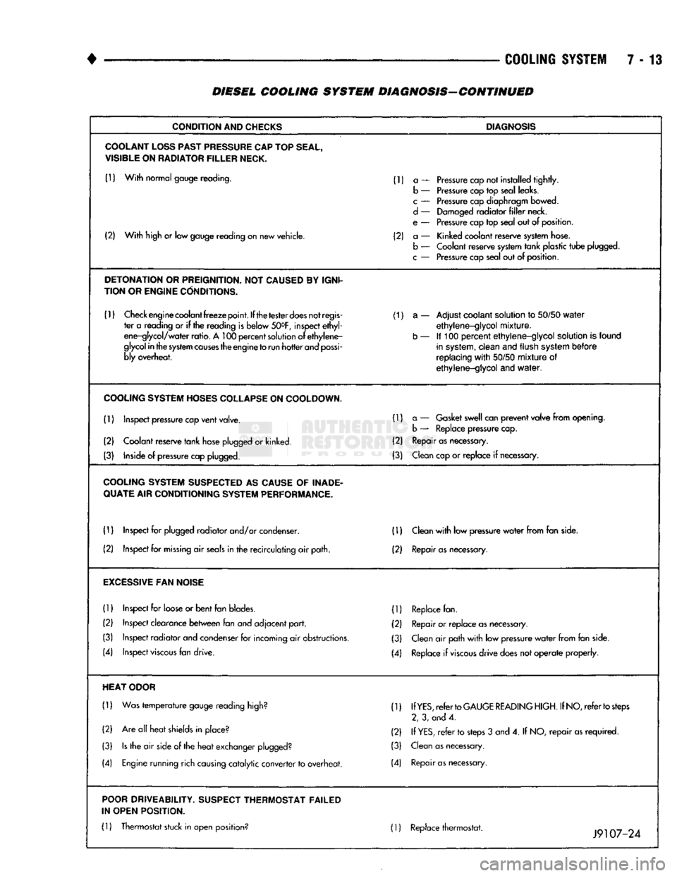
DIESEL COOLING SYSTEM DIAGNOSIS-CONTINUED
CONDITION
AND
CHECKS
DIAGNOSIS
COOLANT
LOSS
PAST
PRESSURE
CAP
TOP
SEAL,
VISIBLE
ON
RADIATOR
FILLER
NECK.
(1)
With
normal gauge reading. (1) a — Pressure cap not installed
tightly.
b — Pressure cap top seal leaks.
c
— Pressure cap diaphragm bowed.
d
— Damaged
radiator
filler
neck.
e — Pressure cap top seal out of position.
(2)
With
high or low gauge reading on new vehicle. (2) a — Kinked coolant reserve system hose.
(2)
With
high or low gauge reading on new vehicle.
b — Coolant reserve system
tank
plastic
tube
plugged.
c
— Pressure cap seal out of position.
DETONATION
OR
PREIGNITION.
NOT
CAUSED
BY
IGNI
TION OR
ENGINE
CONDITIONS.
(1)
Check engine coolant
freeze
point.
If the
tester
does
not
regis
(1) a — Adjust coolant solution to
50/50
water
ter a reading or if the reading is below 50°F, inspect
ethyl
ethylene-glycol
mixture.
ene-glycol/
water
ratio.
A 100
percent
solution of
ethylene-
b — If 100
percent
ethylene-glycol
solution is found
glycol
in
the
system
causes
the engine
to
run
hotter
and
possi
in system,
clean
and flush system
before
bly overheat.
replacing
with
50/50
mixture
of
ethylene-glycol
and
water.
COOLING
SYSTEM
HOSES
COLLAPSE
ON
COOLDOWN.
(1) Inspect pressure cap
vent
valve. (1) a — Gasket swell can
prevent
valve
from
opening.
b — Replace pressure cap.
(2) Coolant reserve
tank
hose plugged or kinked. (2) Repair as necessary.
(3) Inside of pressure cap plugged. (3) Clean cap or
replace
if necessary.
COOLING
SYSTEM
SUSPECTED
AS
CAUSE
OF
INADE
QUATE
AIR CONDITIONING
SYSTEM
PERFORMANCE.
(1) Inspect for plugged
radiator
and/or condenser. (D Clean
with
low pressure
water
from
fan side.
(2) Inspect for
missing
air
seals
in the
recirculating
air path. (2) Repair
as
necessary.
EXCESSIVE
FAN
NOISE
(1)
Inspect for loose or
bent
fan blades. (1) Replace fan.
(2) Inspect clearance
between
fan and
adjacent
part.
(2) Repair or
replace
as necessary.
(3) Inspect
radiator
and condenser for incoming air obstructions. (3) Clean air path
with
low pressure
water
from
fan side.
(4) Inspect
viscous
fan drive. (4) Replace if
viscous
drive
does not
operate
properly.
HEAT
ODOR
(1)
Was
temperature
gauge reading high? (1) If
YES,
refer
to
GAUGE
READING
HIGH.
If
NO,
refer
to
steps
2, 3, and 4.
(2) Are all
heat
shields in place? (2) If
YES,
refer
to steps 3 and 4. If NO,
repair
as
required.
(3)
Is
the air side of the
heat
exchanger plugged? (3) Clean as necessary.
(4) Engine running rich causing
catalytic
converter
to overheat. (4) Repair
as
necessary.
POOR
DRIVEABILITY.
SUSPECT
THERMOSTAT FAILED
IN OPEN POSITION.
(1)
Thermostat stuck in open position? 01 Replace thermostat. ._ _0 .
Jy
107-24
Page 784 of 1502

•
EXHAUST
SYSTEM
AND
INTAKE MANIFOLD
11 - 25
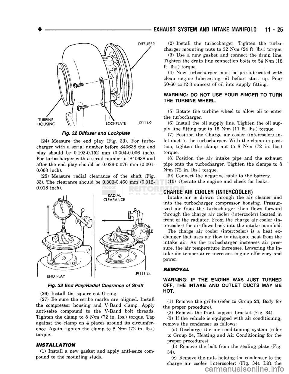
Fig.
32 Diffuser and Lockpiate (24) Measure the end play (Fig. 33). For turbo
charger with a serial number before 840638 the end
play should be 0.102-0.152 mm (0.004-0.006 inch).
For turbocharger with a serial number of 840638 and after the end play should be 0.026-0.076 mm
(0.001-
0.003 inch).
(25) Measure radial clearance of the shaft (Fig.
33).
The clearance should be 0.300-0.460 mm (0.012-
0.018 inch).
Fig.
33 End Play/Radial Clearance of Shaft
(26) Install the square cut O-ring.
(27) Be sure the scribe marks are aligned. Install
the compressor housing and V-Band clamp. Apply anti-seize compound to the V-Band bolt threads.
Tighten the clamp to 8 N-m (72 in. lbs.) torque. Tap against the clamp on 4 places around its circumfer
ence.
Again tighten the clamp to 8 N-m (72 in. lbs.)
torque.
INSTALLATION
(1) Install a new gasket and apply anti-seize com
pound to the mounting studs. (2) Install the turbocharger. Tighten the turbo
charger mounting nuts to 32 N-m (24 ft. lbs.) torque. (3) Use a new gasket and connect the drain line.
Tighten the drain line connection bolts to 24 N-m (18
ft. lbs.) torque.
(4) New turbocharger must be pre-lubricated with
clean engine lubricating oil before start up. Pour 50-60 cc (2-3 ounces) of oil into supply fitting.
WARNING:
DO NOT USE
YOUR FINGER
TO
TURN
THE TURBINE WHEEL.
(5) Rotate the turbine wheel to allow oil to enter
the turbocharger.
(6) Install the oil supply line. Tighten the oil sup
ply line fitting nut to 15 N-m (11 ft. lbs.) torque. (7) Position the Charge air cooler (intercooler) in
let duct to the turbocharger. With the clamp in posi
tion, tighten the clamp nut to 8 N-m (72 in. lbs.) torque.
(8) Position the air intake pipe and the exhaust
pipe onto the turbocharger. Tighten the clamps to 8 N-m (72 in. lbs.) torque.
(9) Connect the negative cable to the battery.
(10) Operate the engine and check for leaks.
CHARGE
AIR
COOLER (INTERCOOLER)
Intake air is drawn through the air cleaner and
into the turbocharger compressor housing. Pressur
ized air from the turbocharger then flows forward
through the charge air cooler (intercooler) located in front of the radiator. From the charge air cooler (in
tercooler) the air flows back into the intake manifold. The charge air cooler (intercooler) is a heat ex
changer that uses air flow to dissipate heat from the
intake air. As the turbocharger increases air pres
sure,
the air temperature increases. Lowering the in
take air temperature increases engine efficiency and
power.
REMOVAL
WARNING:
IF THE
ENGINE
WAS
JUST TURNED OFF,
THE
INTAKE
AND
OUTLET
DUCTS
MAY BE
HOT.
(1) Remove the grille (refer to Group 23, Body for
the proper procedure).
(2) Remove the front support bracket (Fig. 34).
(3) If the vehicle is equipped with air conditioning,
remove the condenser as follows:
(a) Discharge the air conditioning system (refer
to Group 24, Heating and Air Conditioning for the
proper procedures).
(b) Remove the bolt from the sealing plate (Fig.
34).
(c) Remove the nuts holding the condenser to the
charge air cooler (intercooler) (Fig. 34). Lift the