1993 DODGE TRUCK display
[x] Cancel search: displayPage 6 of 1502
INTRODUCTION
INTRODUCTION
DESIGNATIONS,
LABELS/PLATES/DECALS,
CODES
AND DIMENSIONS/WEIGHTS .
CONTENTS
page
MEASUREMENT
AND TORQUE
... 1 SPECIFICATIONS
page
. 11
DESIGNATIONS, LABELS/PLATES/DECALS, CODES
AND
DIMENSIONS/WEIGHTS
INDEX
page
Engine
and
Transmission/Transfer
Case
Identification
2
Engine/Transmission/GVWR
4
Equipment
Identification
Plate
3
International
Vehicle Control
and
Display
Symbols
10
Major Component
Identification 3
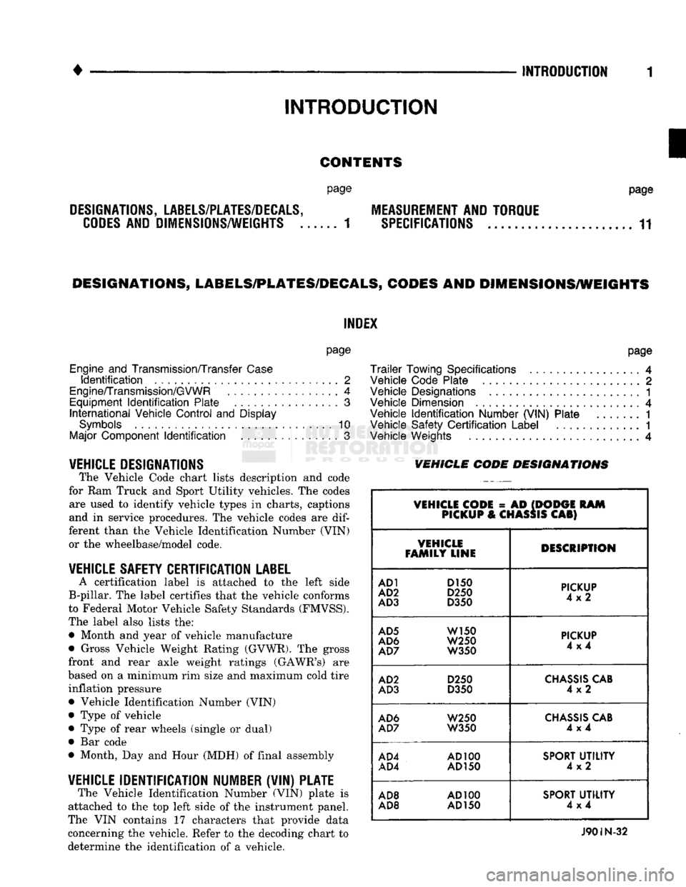
VEHICLE DESIGNATIONS The Vehicle Code chart lists description and code
for Ram Truck and Sport Utility vehicles. The codes are used to identify vehicle types in charts, captions
and in service procedures. The vehicle codes are
dif
ferent than the Vehicle Identification Number (VIN) or the wheelbase/model code.
VEHICLE SAFETY CERTIFICATION
LABEL
A certification label is attached to the left side
B-pillar. The label certifies that the vehicle conforms
to Federal Motor Vehicle Safety Standards (FMVSS).
The label also lists the: • Month and year of vehicle manufacture
• Gross Vehicle Weight Rating (GVWR). The gross
front and rear axle weight ratings (GAWR's) are
based on a minimum rim size and maximum cold tire inflation pressure Vehicle Identification Number (VIN)
Type of vehicle
Type of rear wheels (single or dual) Bar code
Month, Day and Hour (MDH) of final assembly
VEHICLE IDENTIFICATION NUMBER (VIN) PLATE The Vehicle Identification Number (VIN) plate is
attached to the top left side of the instrument panel.
The VIN contains 17 characters that provide data
concerning the vehicle. Refer to the decoding chart to
determine the identification of a vehicle.
page
Trailer
Towing Specifications
4
Vehicle Code Plate
2
Vehicle Designations
1
Vehicle Dimension
4
Vehicle
Identification
Number (VIN) Plate
1
Vehicle Safety
Certification
Label
............. 1
Vehicle Weights
4
VEHICLE CODE
DESIGNATIONS
VEHICLE CODE
= AD
(DODGE
RAM
PICKUP
&
CHASSIS
CAB)
VEHICLE
FAMILY LINE DESCRIPTION
AD1
D150
AD2
D250
AD3
D350
PICKUP
4x2
AD5
W150
AD6
W250
AD7
W350
PICKUP
4x4
AD2
D250
AD3
D350
CHASSIS
CAB
4x2
AD6
W250
AD7
W350
CHASSIS
CAB
4x4
AD4
AD100
AD4
AD150
SPORT
UTILITY
4x2
AD8
AD100
AD8 AD
150
SPORT
UTILITY
4x4
J90IN-32
Page 15 of 1502
10 INTRODUCTION
•
INTERNATIONAL CONTROL AND DISPLAY SYMBOLS
ID
HIGH
BEAM P
FOG UGHTS -&
HEADLIGHTS,
PARKING UGHTS, PANEL UGHTS TURN SIGNAL A
HAZARD WARNING WINDSHIELD
WASHER
WINDSHIELD WIPER WINDSHIELD WIPER
AND WASHER
AND DEFROSTING *
VENTILATING
FAN 8
M f
REAR
WINDOW DEFOGGER
sp
REARWINLX)W WIPER
CD
l
m
REAR
WINDOW WASHER FUEL ENGINE COOLANT
TEMPERATURE BATTERY CHARGING
CONDITION ENGINE OIL
SEAT
BELT
(©) (®) ky
11 J
LIGHTER
BRAKE
FAILURE
PARKING
BRAKE
FRONT HOOD
REAR
HOOD
(TRUNK)
HORN
11 J
LIGHTER
93IN-9
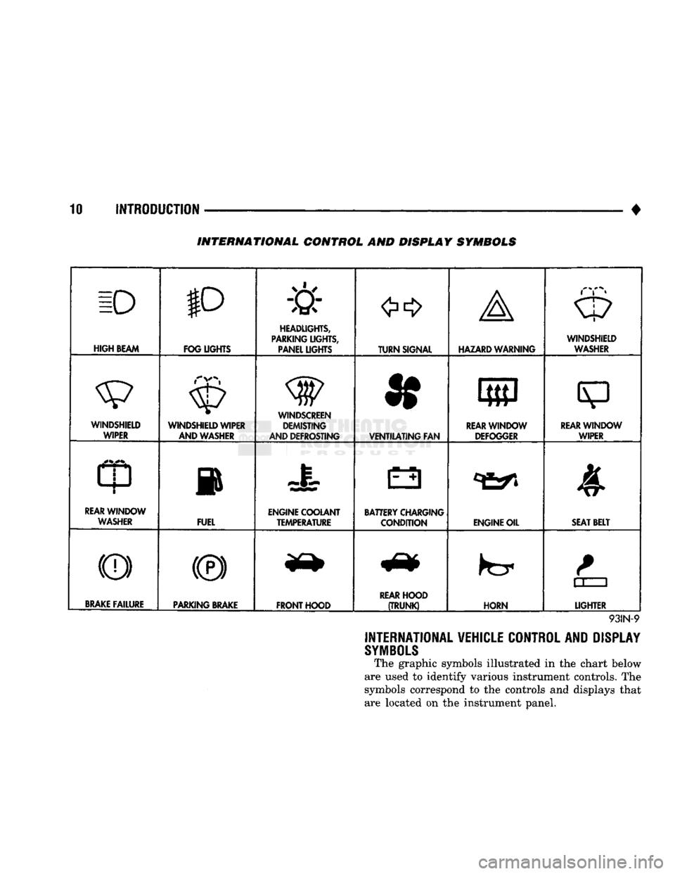
INTERNATIONAL VEHICLE CONTROL AND DISPLAY
SYMBOLS
The graphic symbols illustrated in the chart below
are used to identify various instrument controls. The
symbols correspond to the controls and displays that are located on the instrument panel.
Page 22 of 1502

•
LUBRICATION AND MAINTENANCE
0 - 3
CAUTION: UNLEADED FUEL ONLY must
be
used
in
vehicles equipped
with
a
catalyst emission
control
system.
All
vehicles have reminders
printed
on the
instrument
panel below
the
fuel
gauge
and on the
fuel
filler
door.
The
vehicles also have
fuel
filler
tubes
that
are
specially designed
to
accept only
the
small-diameter nozzles.
It is
illegal
to
bypass
the
design
of an
unleaded
fuel
filler
tube.
DIESEL ENGINES All
Ram
Truck
and Ram
Cab/Chassis Diesel
en
gines normally
can use
number
2D
Diesel fuel
for
most year-round operations.
A
fuel conforming
to
ASTM Specification D-975
is
recommended.
For ex
treme cold-weather, number
ID
Diesel fuel
is
recom mended.
CLASSIFICATION
OF
LUBRICANTS
Lubricating fluids
and
chassis lubricants
are
clas
sified according
to
standards recommended
by the:
• Society
of
Automotive Engineers
(SAE)
• American Petroleum Institute
(API)
• National Lubricating Grease Institute (NLGI)
ENGINE
OIL
SAE
VISCOSITY
GRADE
An
SAE
viscosity grade
is
used
to
specify
the
vis
cosity
of
engine
oil. SAE 30
specifies
a
single viscos
ity engine
oil.
Engine oils also have multiple viscosities. These
are specified with
a
dual
SAE
viscosity grade which
indicates
the
cold-to-hot temperature viscosity range (Fig.
3).
API
SERVICE
GRADE
The
API
Service Grade specifies
the
type
of
perfor
mance
the
engine
oil is
intended
to
provide.
The API
Service Grade specifications also apply
to
energy con
serving engine oils
(Fig. 3).
For maximum gasoline engine protection,
use API
Service Grade
SG,
SG/CD
or
SG/CE engine
oil.
For maximum Diesel engine protection,
use
API Service
CE or
SG/CE engine
oil.
GEAR LUBRICANTS A dual grade
is
also used
to
specify
the
viscosity
of
multi-purpose gear lubricants.
The
API
grade designation identifies gear lubri
cants
in
terms
of
recommended usage.
OIL
QUALITY
SAE
VISCOSITY
GRADE
FUEL
ECONOMY
NOTATION
J91004
Fig.
3 SAE Oil
Viscosity Grade
& API
Service
Grade
CHASSIS COMPONENT
AND
WHEEL BEARING
LUBRICANTS The chassis
and
wheel bearing lubricants
are
iden
tified
by the
NLGI Certification Symbol.
The
symbol
contains
a
coded designation. This identifies
the us
age
and
quality
of the
lubricant.
The letter
G
within
the
symbol designates wheel
bearing lubricant.
The
letter
L
designates chassis
lu
bricant. When
the
letters
are
combined,
the
lubricant can
be
used
for
dual applications.
Use
only lubricants
that display
the
NLGI Certification Symbol.
NATIONAL LUBRICATING
GREASE
INSTITUTE
NLGI
AUTOMOTIVE
WHEEL BEARING
&
CHASSIS LUBRICANT
GC-LB
-CERTIFICATION
SYMBOL
—
USAGE
AND
QUALITY
DESIGNATION
J920W7
Fig.
4
NLGI
Lubricant Container
Certification/
Identification
Symbol
LUBRICATION
AND
REPLACEMENT
PARTS
RECOMMENDATION
Ram Trucks
are
engineered
to
provide many years
of dependable operation. However, lubrication service
and maintenance
are
required
for
each vehicle. When
necessary, MOPAR®brand lubricants
and
genuine
re
placement parts
are
recommended.
Page 249 of 1502
i - 62
BRAKES
•
Isolation/Dump
Valve Cycle Times
Activation (opening/closing) of the isolation and
dump valves is continuous during antilock operation.
The valves cycle rapidly in response to speed sensor inputs and control module signal commands. Cycle
times are measured in milliseconds.
As the demand for antilock mode brake operation
is decreased, the module deactivates the hydraulic
valve components to restore normal brake operation.
ANTILOCK
SERVICE
DIAGNOSIS
GENERAL INFORMATION An antilock system malfunction will be indicated
by illumination of the amber antilock warning lamp.
The red brake warning lamp may also illuminate.
If a problem occurs, system diagnosis should begin
with a fluid level check followed by a visual exami
nation of the system electrical and hydraulic connec
tions.
If obvious defects (low fluid, leaks, loose connections, etc.) are not evident, road test the vehi
cle.
A road test should help determine if a malfunc
tion is actually related to an antilock component.
During the road test, note if other conditions are
evident such as a low pedal, pull, grab, or similar condition. Remember that brake malfunctions such as low fluid, system leaks, parking brakes partially
applied, will also affect the antilock system. The idea
is to determine if a malfunction is actually related to
an anti-lock component.
If a road test does reveal a problem, repeat the
road test with the owner driving. Make sure the owner is not riding the brake pedal, or has forgotten
to release the parking brakes. Either situation will
generate a fault and cause the antilock light to illu
minate.
SYSTEM FAULT
CODES
The antilock control module generates flash codes
to help identify the cause of an antilock system fault. Two different control modules are used with the
1992/1993 RWAL system. A type I module is used in
some early production models. All remaining produc
tion models are equipped with a type II module. The type I and II modules are identified by the way
fault codes 9 and 11 are processed. If the vehicle has a type I module, codes 9 and 11 are not erased when
the ignition switch is turned to Off position. If the vehicle has a type II module, codes 9 and 11 are
erased when the switch is turned to Off.
FAULT CODES WITH TYPE I CONTROL
MODULE
The microprocessor in the electronic control module
has a memory and a self test feature. The self test
feature is activated whenever the ignition switch is
turned to Accessory or Run position. If a system fault is detected, the control module il
luminates the antilock light and stores the fault code
in memory. Fault codes are retained in memory even after turning the ignition switch to Off position.
FAULT CODES WITH TYPE II CONTROL
MODULE The microprocessor in the electronic control module
has a memory and a self test feature. The self test
feature is activated whenever the ignition switch is
turned to Accessory or Run position.
If a system fault is detected, the control module
will illuminate the antilock indicator lamp and store
fault codes 1 through 8, 10 and 12 through 15 in the
microprocessor memory. When one of these fault
codes is generated, the control module will retain the code after the ignition switch is turned to the Off po
sition.
When fault code 9 is generated, the code only re
mains in microprocessor memory while the ignition switch is in Run position. Turning the ignition
switch to Off position erases fault code 9. However, if
the problem still exists when the switch is turned
back to Run position, code 9 will reappear in memory after 20 seconds and the antilock light will illumi
nate once again.
When fault code 11 is generated, the antilock light
will illuminate when vehicle speed exceeds approxi mately 60.35 km/h (37.5 mph). Code 11 only remains in memory while the ignition switch is in the Run
position and the fault is present.
When the cause of a fault code 11 is corrected, the
antilock light goes off. Code 11 is erased when the ig
nition switch is turned to Off position. However, if
the problem cause still exists when the ignition switch is turned to Run position, code 11 will reap
pear when vehicle speed exceeds approximately 60.35 km/h (37.5 mph).
FAULT
CODE
CAPACITY
The microprocessor memory will store and display
only one fault code at a time. The stored code can be
displayed by grounding the RWAL diagnostic connec
tor.
FAULT
CODE
IDENTIFICATION
To determine what the fault code is, momentarily
ground the RWAL diagnostic connector and count
the number of times the amber antilock lamp flashes. Fault codes and typical malfunctions are outlined in Figure 8. Note that when a fault code is gen
erated, the red brake warning lamp will also
illuminate. The initial flash will be a long flash followed by a
number of short flashes. The long flash indicates the
beginning of the fault number sequence and the short flashes are a continuation of that sequence.
Page 316 of 1502
•
COOLING
SYSTEM
7 - 45 (3) Rotate socket/wrench counterclockwise. Install
belt over tensioner pulley. Let tensioner rotate back into place. Remove wrench. Be sure belt is properly
seated on all pulleys.
5«9L
DIESEL ENGINE
REMOVAL
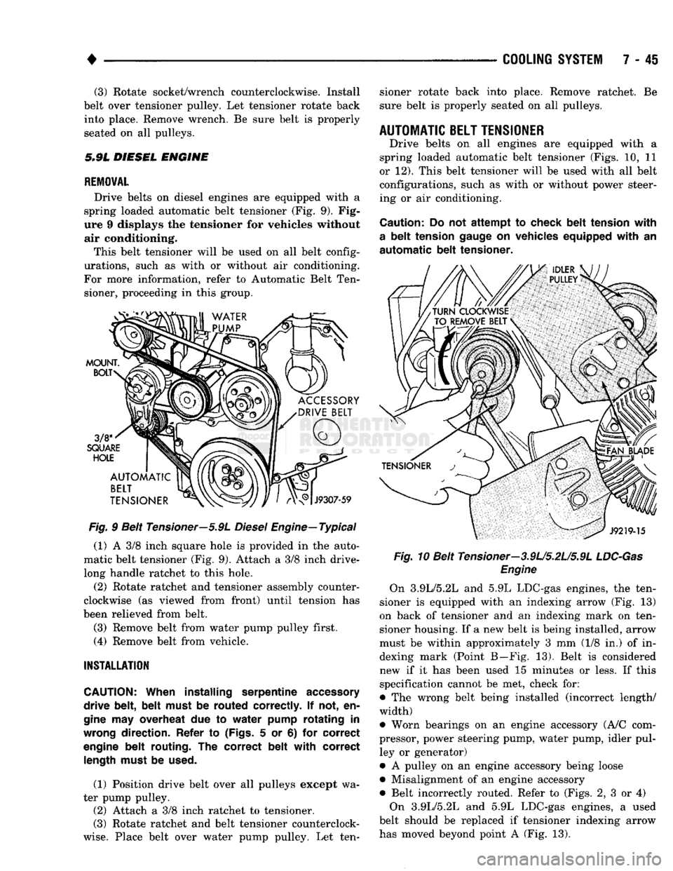
Drive belts on diesel engines are equipped with a
spring loaded automatic belt tensioner (Fig. 9). Fig
ure 9 displays the tensioner for vehicles without air conditioning.
This belt tensioner will be used on all belt config
urations, such as with or without air conditioning.
For more information, refer to Automatic Belt Ten sioner, proceeding in this group.
Fig.
9 Belt Tensioner—5.9L
Diesel
Engine—Typical
(1) A 3/8 inch square hole is provided in the auto
matic belt tensioner (Fig. 9). Attach a 3/8 inch drive-
long handle ratchet to this hole.
(2) Rotate ratchet and tensioner assembly counter
clockwise (as viewed from front) until tension has
been relieved from belt.
(3) Remove belt from water pump pulley first.
(4) Remove belt from vehicle.
INSTALLATION
CAUTION:
When installing serpentine
accessory
drive belt, belt must
be
routed correctly.
If not, en
gine
may
overheat
due to
water pump rotating
in
wrong
direction. Refer
to
(Figs.
5 or 6) for
correct
engine
belt routing.
The
correct belt with correct
length
must
be
used.
(1) Position drive belt over all pulleys except wa
ter pump pulley. (2) Attach a 3/8 inch ratchet to tensioner.
(3) Rotate ratchet and belt tensioner counterclock
wise.
Place belt over water pump pulley. Let ten sioner rotate back into place. Remove ratchet. Be
sure belt is properly seated on all pulleys.
AUTOMATIC
BELT
TENSIONER
Drive belts on all engines are equipped with a
spring loaded automatic belt tensioner (Figs. 10, 11
or 12). This belt tensioner will be used with all belt configurations, such as with or without power steer
ing or air conditioning.
Caution:
Do not
attempt
to
check belt tension with
a
belt tension
gauge
on
vehicles equipped with
an
automatic
belt tensioner. Fig.
10 Belt Tensioner—3.9U5.2U5.9L
LDC-Gas
Engine
On 3.9L/5.2L and 5.9L LDC-gas engines, the ten
sioner is equipped with an indexing arrow (Fig. 13)
on back of tensioner and an indexing mark on ten
sioner housing. If a new belt is being installed, arrow
must be within approximately 3 mm (1/8 in.) of in dexing mark (Point B—Fig. 13). Belt is considered
new if it has been used 15 minutes or less. If this
specification cannot be met, check for:
• The wrong belt being installed (incorrect length/
width)
• Worn bearings on an engine accessory (A/C com
pressor, power steering pump, water pump, idler pul ley or generator)
• A pulley on an engine accessory being loose
• Misalignment of an engine accessory
• Belt incorrectly routed. Refer to (Figs. 2, 3 or 4) On 3.9L/5.2L and 5.9L LDC-gas engines, a used
belt should be replaced if tensioner indexing arrow
has moved beyond point A (Fig. 13).
Page 338 of 1502
•
ELECTRICAL
8A - 17
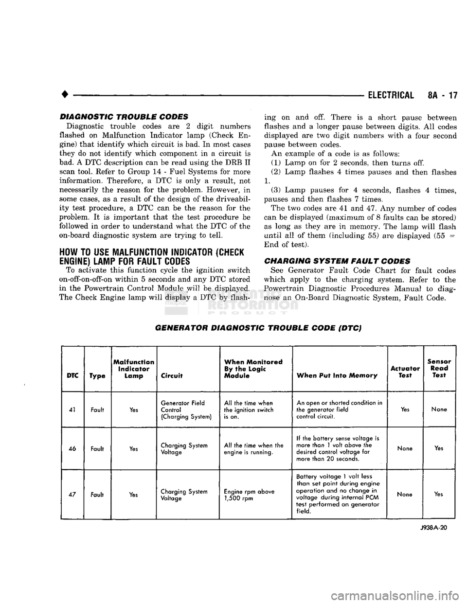
DIAGNOSTIC
TROUBLE
CODES
Diagnostic trouble codes are 2 digit numbers
flashed on Malfunction Indicator lamp (Check En
gine) that identify which circuit is bad. In most cases
they do not identify which component in a circuit is
bad. A DTC description can be read using the DRB II scan tool. Refer to Group 14 - Fuel Systems for more
information. Therefore, a DTC is only a result, not
necessarily the reason for the problem. However, in
some cases, as a result of the design of the driveabil- ity test procedure, a DTC can be the reason for the
problem. It is important that the test procedure be followed in order to understand what the DTC of the
on-board diagnostic system are trying to tell.
HOW
TO
USE
MALFUNCTION
INDICATOR
(CHECK
ENGINE)
LAMP
FOR
FAULT
CODES
To activate this function cycle the ignition switch
on-off-on-off-on within 5 seconds and any DTC stored
in the Powertrain Control Module will be displayed.
The Check Engine lamp will display a DTC by flash ing on and off. There is a short pause between
flashes and a longer pause between digits. All codes
displayed are two digit numbers with a four second
pause between codes. An example of a code is as follows:
(1) Lamp on for 2 seconds, then turns off.
(2) Lamp flashes 4 times pauses and then flashes
1.
(3) Lamp pauses for 4 seconds, flashes 4 times,
pauses and then flashes 7 times.
The two codes are 41 and 47. Any number of codes
can be displayed (maximum of 8 faults can be stored) as long as they are in memory. The lamp will flash
until all of them (including 55) are displayed (55 =
End of test).
CHARGING
SYSTEM
FAULT
CODES
See Generator Fault Code Chart for fault codes
which apply to the charging system. Refer to the
Powertrain Diagnostic Procedures Manual to diag
nose an On-Board Diagnostic System, Fault Code.
GENERATOR
DIAGNOSTIC
TROUBLE
CODE
(DTC)
DTC
Type
Malfunction
Indicator
Lamp
Circuit
When
Monitored
By
the
Logic
Module
When
Put Into
Memory
Actuator
Test
Sensor
Read
Test
41 Fault
Yes
Generator Field
Control
(Charging
System)
All the
time
when
the ignition switch
is
on.
An
open or shorted condition in
the generator
field
control circuit.
Yes
None
46 Fault
Yes
Charging
System
Voltage
All the
time
when the
engine
is
running.
If the
battery
sense
voltage is
more than 1 volt
above
the
desired
control voltage for
more than 20
seconds.
None
Yes
47 Fault
Yes
Charging
System
Voltage
Engine
rpm
above
1,500 rpm Battery voltage
1
volt
less
than set point during engine
operation and no
change
in
voltage
during
internal
PCM
test performed on generator field.
None
Yes
J938A-20
Page 342 of 1502
• BATTERY/STARTER/GENERATOR
SERVICE
8B - 1
CONTENTS
page page
BATTERY
SERVICE
PROCEDURES
1 SPECIFICATIONS 9
GENERATOR
SERVICE
6 STARTER
SERVICE
PROCEDURES
4
BATTERY SERVICE PROCEDURES
GENERAL
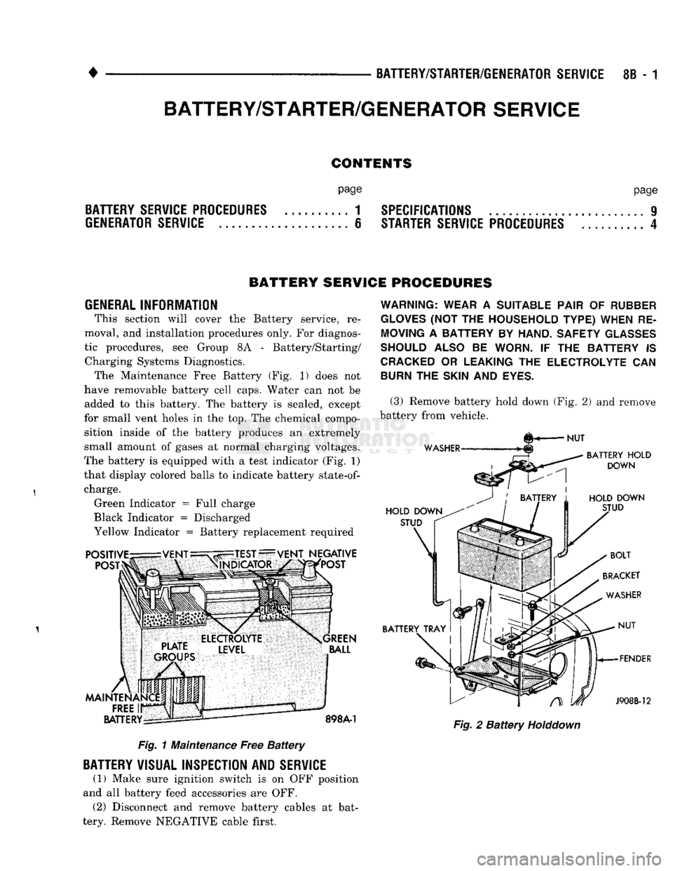
INFORMATION This section will cover the Battery service, re
moval, and installation procedures only. For diagnos
tic procedures, see Group 8A - Battery/Starting/ Charging Systems Diagnostics. The Maintenance Free Battery (Fig. 1) does not
have removable battery cell caps. Water can not be added to this battery. The battery is sealed, except
for small vent holes in the top. The chemical compo sition inside of the battery produces an extremely
small amount of gases at normal charging voltages.
The battery is equipped with a test indicator (Fig. 1)
that display colored balls to indicate battery
state-of-
charge. Green Indicator = Full charge
Black Indicator = Discharged
Yellow Indicator = Battery replacement required Fig. 1 Maintenance Free Battery
BATTERY
VISUAL INSPECTION AND
SERVICE
(1) Make sure ignition switch is on OFF position
and all battery feed accessories are OFF. (2) Disconnect and remove battery cables at bat
tery. Remove NEGATIVE cable first.
WARNING: WEAR
A
SUITABLE PAIR
OF
RUBBER
GLOVES
(NOT THE
HOUSEHOLD TYPE) WHEN
RE
MOVING
A
BATTERY
BY
HAND. SAFETY
GLASSES
SHOULD ALSO
BE
WORN.
IF THE
BATTERY
IS
CRACKED
OR
LEAKING
THE
ELECTROLYTE
CAN
BURN
THE
SKIN
AND
EYES.
(3) Remove battery hold down (Fig. 2) and remove
battery from vehicle. Fig. 2 Battery
Holddown
BATTERY/STARTER/GENERATOR
SERVICE
Page 359 of 1502
8D
- 8
IGNITION
SYSTEMS
• If sync pulse signal is not present, replacement of
the camshaft position sensor is necessary. For removal or installation of ignition system com
ponents, refer to the Component Removal/Installa
tion section of this group.
For system operation and component identification,
refer to the Component Identification/System Opera
tion section of this group.
CRANKSHAFT POSITION
SENSOR
TEST
To perform a complete test of this sensor and its
circuitry, refer to the DRB II diagnostic scan tool.
Also refer to the appropriate Powertrain Diagnostics
Procedures manual. To test the sensor only, refer to
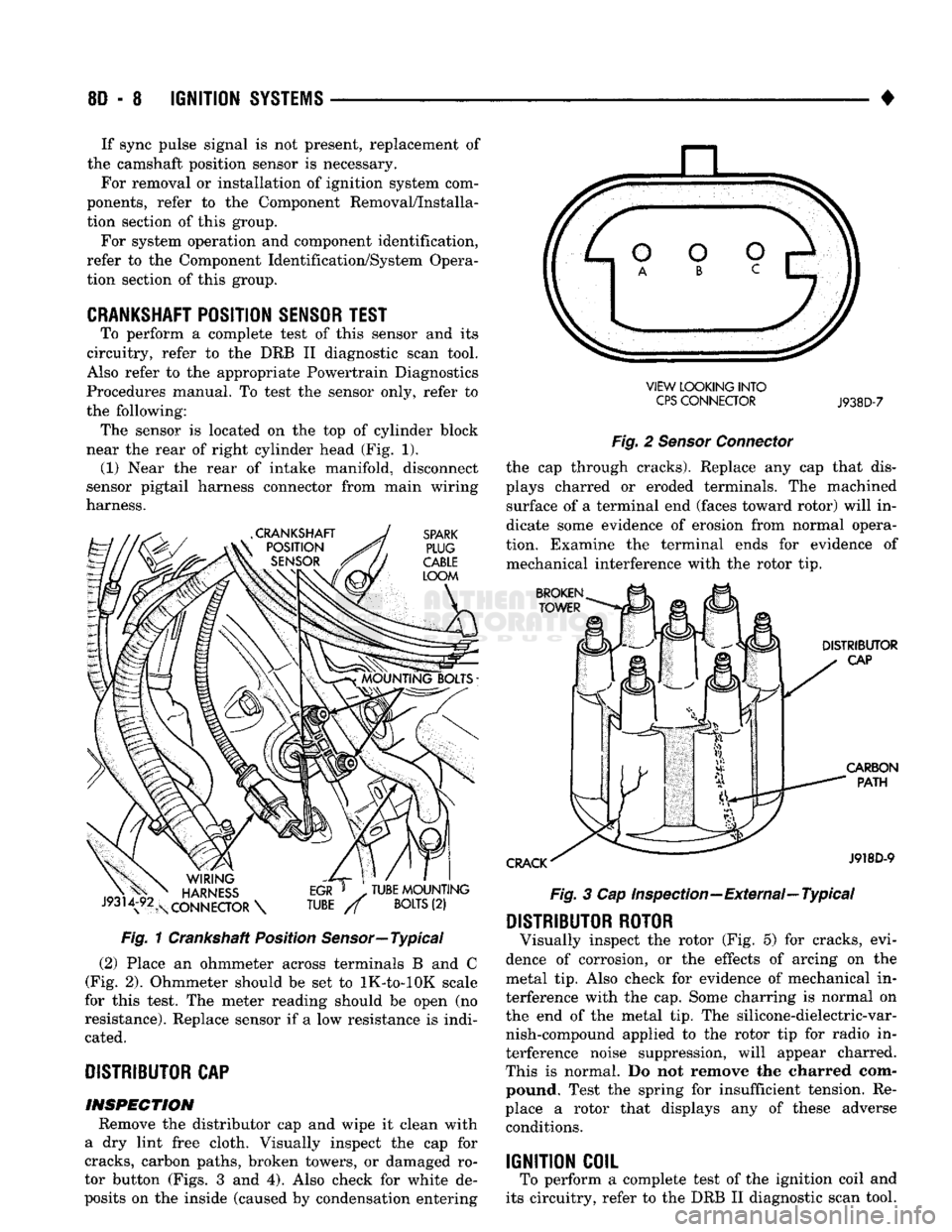
the following: The sensor is located on the top of cylinder block
near the rear of right cylinder head (Fig. 1). (1) Near the rear of intake manifold, disconnect
sensor pigtail harness connector from main wiring
harness. Fig. 1 Crankshaft Position Sensor—Typical
(2) Place an ohmmeter across terminals B and C
(Fig. 2). Ohmmeter should be set to lK-to-lOK scale
for this test. The meter reading should be open (no
resistance). Replace sensor if a low resistance is indi cated.
DISTRIBUTOR
CAP INSPECTION Remove the distributor cap and wipe it clean with
a dry lint free cloth. Visually inspect the cap for
cracks, carbon paths, broken towers, or damaged ro
tor button (Figs. 3 and 4). Also check for white de
posits on the inside (caused by condensation entering VIEW LOOKING INTO
CPS
CONNECTOR
J938D-7
Fig. 2 Sensor Connector the cap through cracks). Replace any cap that dis
plays charred or eroded terminals. The machined surface of a terminal end (faces toward rotor) will in
dicate some evidence of erosion from normal opera
tion. Examine the terminal ends for evidence of mechanical interference with the rotor tip. Fig. 3 Cap Inspection—External—Typical
DISTRIBUTOR ROTOR
Visually inspect the rotor (Fig. 5) for cracks, evi
dence of corrosion, or the effects of arcing on the
metal tip. Also check for evidence of mechanical in
terference with the cap. Some charring is normal on
the end of the metal tip. The silicone-dielectric-var nish-compound applied to the rotor tip for radio in
terference noise suppression, will appear charred.
This is normal. Do not remove the charred com pound. Test the spring for insufficient tension. Re
place a rotor that displays any of these adverse conditions.
IGNITION COIL
To perform a complete test of the ignition coil and
its circuitry, refer to the DRB II diagnostic scan tool.