1993 DODGE TRUCK display
[x] Cancel search: displayPage 365 of 1502

8D
- 14
IGNITION SYSTEMS
• (5) Test the MAP sensor ground circuit at sensor
connector terminal-A (Fig. 19) and PCM connector
terminal-4. Repair the wire harness if necessary.
(6) Test the MAP sensor ground circuit at the
PCM connector between terminal-4 and terminal-11
with an ohmmeter. If the ohmmeter indicates an
open circuit, inspect for a defective sensor ground
connection. Refer to Group 8W, Wiring for location of
this connection. If the ground connection is good, re
place the PCM. If terminal-4 has a short circuit to 12 volts +, correct this condition before replacing the
PCM.
POWERTRAIN
CONTROL MODULE {PCM)
The PCM (formerly called the SBEC or engine -con
troller) is located in the engine compartment (Fig.
20). DATA UNK CONTROL
CONNECTOR MODULE
J9314-164
Fig.
20 PCM Location The ignition system is controlled by the PCM.
For removal and installation of this component, re
fer to the Component Removal/Installation section of
this group.
For diagnostics, refer to the appropriate Powertrain
Diagnostic Procedures service manual for operation
of the DRB II scan tool.
SPARK
PLUGS
For spark plug removal, cleaning, gap adjustment
and installation, refer to the Component Removal/In
stallation section of this group. Spark plug cable boot heat shields are pressed into
the cylinder head to surround each cable boot and
spark plug (Fig. 21). These shields protect the spark
plug boots from damage (due to intense engine heat
generated by the exhaust manifolds) and should not
be removed. After the spark plug cable has been in stalled, the lip of the cable boot should have a small
air gap to the top of the heat shield (Fig. 21). Faulty carbon and/or gas fouled plugs generally
cause hard starting, but they will clean up at higher
engine speeds. Faulty plugs can be identified in a
Fig.
21 Heat
Shields
number of ways: poor fuel economy, power loss, de
crease in engine speed, hard starting and, in general,
poor engine performance.
Remove the spark plugs and examine them for
burned electrodes and fouled, cracked or broken por celain insulators. Keep plugs arranged in the order
in which they were removed from the engine. An iso
lated plug displaying an abnormal condition indi
cates that a problem exists in the corresponding
cylinder. Replace spark plugs at the intervals recom
mended in the maintenance chart in Group 0, Lubri
cation and Maintenance.
Spark plugs that have low mileage may be cleaned
and reused if not otherwise defective. Refer to the
following Spark Plug Condition section of this group.
CONDITION
NORMAL OPERATING
The few deposits present on the spark plug will
probably be light tan or slightly gray in color. This is evident with most grades of commercial gasoline (Fig. 22). There will not be evidence of electrode
burning. Gap growth will not average more than ap proximately 0.025 mm (.001 in) per 1600 km (1000
miles) of operation. Spark plugs that have normal
wear can usually be cleaned, have the electrodes filed, have the gap set and then be installed.
Some fuel refiners in several areas of the United
States have introduced a manganese additive (MMT)
for unleaded fuel. During combustion, fuel with
MMT causes the entire tip of the spark plug to be coated with a rust colored deposit. This rust color can
be misdiagnosed as being caused by coolant in the combustion chamber. Spark plug performance is not affected by MMT deposits.
COLD
FOULING/CARBON FOULING
Cold fouling is sometimes referred to as carbon
fouling. The deposits that cause cold fouling are ba-
Page 384 of 1502
•
INSTRUMENT PANEL
AND
GAUGES
8E - 3
MALFUNCTION INDICATOR (CHECK ENGINE)
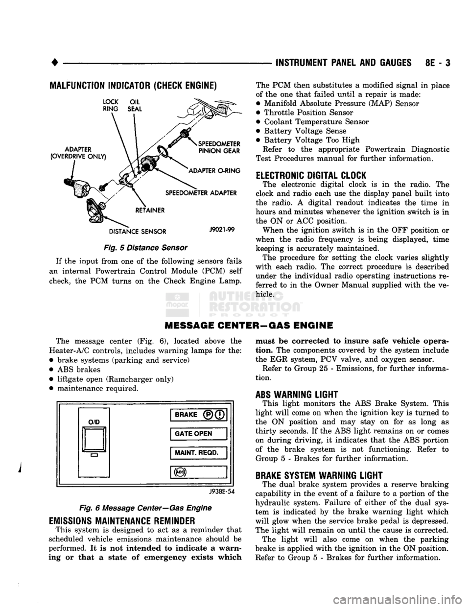
Fig.
5
Distance Sensor
If
the
input from
one of the
following sensors fails
an internal Powertrain Control Module
(PCM)
self
check,
the PCM
turns
on the
Check Engine Lamp. The
PCM
then substitutes
a
modified signal
in
place
of
the one
that failed until
a
repair
is
made:
• Manifold Absolute Pressure (MAP) Sensor
• Throttle Position Sensor
• Coolant Temperature Sensor
• Battery Voltage Sense
• Battery Voltage
Too
High
Refer
to the
appropriate Powertrain Diagnostic
Test Procedures manual
for
further information.
ELECTRONIC DIGITAL CLOCK
The electronic digital clock
is in the
radio.
The
clock
and
radio each
use the
display panel built into
the radio.
A
digital readout indicates
the
time
in
hours
and
minutes whenever
the
ignition switch
is in
the
ON or ACC
position. When
the
ignition switch
is in the OFF
position
or
when
the
radio frequency
is
being displayed, time keeping
is
accurately maintained. The procedure
for
setting
the
clock varies slightly
with each radio.
The
correct procedure
is
described under
the
individual radio operating instructions
re
ferred
to in the
Owner Manual supplied with
the ve
hicle.
MESSAGE CENTER—GAS ENGINE
The message center
(Fig. 6),
located above
the
Heater-A/C controls, includes warning lamps
for the:
• brake systems (parking
and
service)
•
ABS
brakes • liftgate open (Ramcharger only)
• maintenance required.
O/D
BRAKE
(P)(7
GATE OPEN
MAINT
REQD.
J938E-54
Fig.
6
Message Center—Gas Engine
EMISSIONS
MAINTENANCE REMINDER
This system
is
designed
to act as a
reminder that
scheduled vehicle emissions maintenance should
be
performed.
It is not
intended
to
indicate
a
warn
ing
or
that
a
state
of
emergency exists which must
be
corrected
to
insure safe vehicle opera
tion.
The
components covered
by the
system include
the
EGR
system,
PCV
valve,
and
oxygen sensor. Refer
to
Group
25 -
Emissions,
for
further informa
tion.
ABS
WARNING
LIGHT
This light monitors
the ABS
Brake System. This
light will come
on
when
the
ignition
key is
turned
to
the
ON
position
and may
stay
on for as
long
as
thirty seconds.
If the ABS
light remains
on or
comes on during driving,
it
indicates that
the ABS
portion
of
the
brake system
is not
functioning. Refer
to
Group
5 -
Brakes
for
further information.
BRAKE
SYSTEM WARNING
LIGHT
The dual brake system provides
a
reserve braking
capability
in the
event
of a
failure
to a
portion
of the
hydraulic system. Failure
of
either
of the
dual sys
tem
is
indicated
by the
brake warning light which
will glow when
the
service brake pedal
is
depressed.
The light will remain
on
until
the
cause
is
corrected. The light will also come
on
when
the
parking
brake
is
applied with
the
ignition
in the ON
position.
Refer
to
Group
5 -
Brakes
for
further information.
Page 404 of 1502
AUDIO SYSTEMS
CONTENTS
SERVICE
PROCEDURES
page
.. 7
TEST PROCEDURES
page
.. 2
GENERAL
INFORMATION
For operation of the factory installed radios, refer
to the Owner Manual supplied with the vehicle. When connecting or disconnecting the Ignition Off
Draw (IOD) connector, it is important that the igni
tion switch be in the OFF position. Failure to place the ignition switch in the OFF po
sition can cause the radio display to become scram
bled when the IOD is disconnected. Connecting the IOD will correct the scrambled display.
INTERFERENCE
ELIMINATION
Many components are used on vehicles equipped
with a radio to suppress radio frequency interference (static). A capacitor is mounted inside the generator and
ground straps are utilized from cab to box and from
the engine to cowl. The previously mentioned Capacitor and Ground
Straps should be securely mounted to a clean ground
surface to work effectively. Radio resistance spark plug wires complete the in
terference suppression system. Faulty or deteriorated spark plug wires should be replaced.
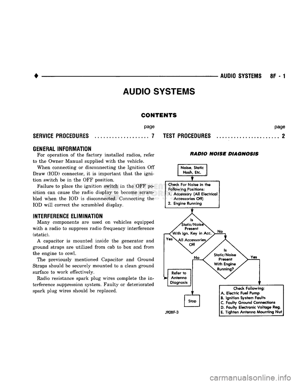
RADIO NOISE DIAGNOSIS
Noise,
Static
Hash,
Etc.
Check
For Noise in
the
Following
Positions:
1.
Accessory (All Electrical
Accessories
Off)
2. Engine Running
Is
'Static/NoiseS
Present
'With
Ign.
Key in Acc.
Yes\^|j
Accessories/
Off
No
Refer
to
Antenna
Diagnosis
f
Stop
No
Is
Static/Noise Present
With Engine
Running?.
Yes
J928F-3
Check
Following:
A.
Electric
Fuel
Pump
B.
Ignition
System
Faults
C.
Faulty Ground Connections
D.
Faulty Electronic Voltage Reg.
E.
Tighten Antenna Mounting Nut
Page 422 of 1502
•
VEHICLE
SPEED
CONTROL SYSTEM
8H - 7
TEST
PROCEDURES
INDEX
page
Checking
for
Diagnostic
Trouble
Code
7
General
Information
7
Inoperative
System
7
Road
Test
7
Speed
Control
Cable Adjustment—Diesel Engine
. 9
Speed
Control
Cable
Attachment
10
GENERAL
INFORMATION
Before starting diagnosis and repair procedures for
a speed control malfunction, verify that the speed
control wire harness is properly connected to all con nectors. Refer to Diagnosis Chart.
ROAD
TEST
Road test vehicle to verify reports of speed control
system malfunction. The road test should include at
tention to the speedometer. Speedometer operation should be smooth and without flutter at all speeds. Flutter in the speedometer indicates a problem
which might cause surging in the speed control sys
tem. The cause of any speedometer deficiencies should be corrected before proceeding.
INOPERATIVE SYSTEM
If road test verifies a system problem and the
speedometer operates properly, check for:
• loose electrical and vacuum connections at the
servo.
• check for correct installation of the vacuum check
valve in the hose from servo to vacuum source (Gas
Engine Only). The word VAC on the valve must
point toward the vacuum source. • corrosion that should be removed from electrical
terminals and a light coating of Mopar Multi-Pur
pose Grease, or equivalent, applied. • secure attachment of both ends of speed control ca
ble.
CHECKING
FOR DIAGNOSTIC TROUBLE CODE
(1) When trying to verify a speed control system
electrical problem, use a DRB II Scan Tool to find
the cause. Refer to Powertrain Diagnostic Procedures manual. If the DRBII is not available, the Diagnostic Trou
ble Code (DTC) may be determined with the follow ing method: (a) With key inserted in ignition switch, cycle
switch to ON position 3 times. On third cycle, leave
switch in ON position. (b) After switch has been cycled 3 times, observe
Malfunction Indicator Lamp (CHECK ENGINE) on instrument cluster. If a DTC is present, the code
page
Speed
Control
Cable Attachment—Servo
10
Stop Lamp Switch Test
9
Vacuum Supply Test
....................... 9
Vehicle Speed
Control
Switch Test
. 9
Vehicle Speed
Control
System
Electrical
Tests
... 7
Vehicle Speed Sensor Test
7
will be displayed in a series of flashes representing
digits.
Three flashes in rapid succession, a slight
pause, then 4 flashes in rapid succession would in dicate DTC 34.
(2) If a DTC 34 is observed, perform the tests in
the sections Electrical Tests at Servo and Electrical
Tests at Powertrain Control Module.
If a DTC 15 is observed, perform the test for a
faulty Vehicle Speed Sensor.
(3) If a fault code 11 is observed (Diesel only), per
form the test for a faulty engine speed sensor. Refer
to the Powertrain Diagnostics Procedures Manual.
(4) Correct any problems found when performing
these tests and recheck for DTC if changes were made.
VEHICLE SPEED SENSOR TEST
For testing of the Vehicle Speed Sensor and related
components refer to the Powertrain Diagnostic Proce
dures manual.
VEHICLE SPEED CONTROL SYSTEM ELECTRICAL
TESTS
Vehicle speed control systems may be tested using
two different methods. One involves the use of the DRBII Scan Tool. If this test method is desired,
please refer to the Powertrain Diagnostic Procedures manual. The other test method uses a voltmeter. The volt
meter method is described in the following tests.
If any information is needed concerning wiring, re
fer to Group 8W - Wiring Diagrams.
CAUTION:
When test probing
for
voltage
or
continuity
at
electrical
connectors, care must
be
taken
not
to
damage connector, terminals,
or
seals.
If
these components
are
damaged,
intermittent
or
complete system
failure
may
occur.
ELECTRICAL
TESTS
AT
SERVO
(1) Turn ignition switch to ON position.
(2) Push speed control switch to ON position.
(3) Connect the negative lead of a voltmeter to a
good chassis ground near the servo.
Page 517 of 1502
8W
- 42
WIRING DIAGRAMS
-J_
ENGINE
=
GROUND
BODY
—
GROUND
BATTERY
-A
15
22WT-
^—
FUSIBLE LINK
(22WT)
(LEFT
FRONT WHEELHOUSE) FUSIBLE LINK
(18GY)
(LEFT
FRONT WHEELHOUSE)
All
6BK/GY FUSIBLE LINK
{1000)50/120 AMP
(LEFT
FRONT WHEELHOUSE) A15
16PK
13#-ZI
L9
18BK WT
i
HAZARD
FLASHER
SH
56
IT-
FUSE
#13
20 AMP
O
FUSE
#4
|
ft 20 AMP
F33
18PK
RD
A3
12RD WT A3
12RD WT
4-
CHARGING
SYSTEM
SH
3,4,5.6
FUSE
#6 20 AMP
FUSE
#5
J—1| 20 AMP
F33
18PK
RD
HORNS
SH
30
POWER DOOR LOCKS
SH
73
CIRCUIT
BREAKER
HEADLAMP
•VWf
SWITCH
EI
18TN
SH
47
-L2 HEADLAMPS
DIMMER SWITCH
SH
47
F32
18PK
DB
I
STOP LAMPS
SH
79,80
KEY-IN
I
HEADLAMP
ON
BUZZER
SH
77.78
REAR
WHEEL ANTI-LOCK
SH
31.33
FUSE
#15
10 AMP
L7
18BK/YL-
3
FUSE
#14
D 3AMP
E2
200R
X
CLUSTER LAMPS
SH
59
RADIO LAMPS
SH
61.63.65
A/C
AND
HEATER CONTROL LAMP
SH
48
ASH
RECEIVER LAMP
SH
48
TACHOMETER LAMP
SH
48
TRANSMISSION OVERDRIVE INDICATOR LAMP
SH
12
HEATED REAR WINDOW SWITCH LAMP
SH
39
PARKING LAMPS
SH
43.44.45,46
TAIL
LAMPS
SH
79.80
LICENSE
LAMP
SH
80
FRONT SIDE MARKER
LAMPS
SH
43.44.45.46
RADIO DISPLAY INTENSITY
SH
61.63.65
CLEARANCE
AND
IDENTIFICATION
LAMPS
SH
40.41
UNDERHOOD LAMP
SH
29
GLOVE
BOX
LAMP
SH
52
RADIO ELECTRONICS
SH
61.63.65
MAP LAMP
SH
49
IGNITION
SWITCH LAMP
SH
49
DOME LAMP
SH
50.51
CARGO
LAMPS
SH
49.50
POWER MIRRORS
SH
75
A31
14BK/WT
-
7*3
LI FUSE
#7
2h-i
15 AMP
F30
16RD TN
1
CIGAR LIGHTER
SH
52
AD
1
FUSE
APPLICATION CHART
J938W-U
Page 829 of 1502
FUEL
TUBE
REMOVAL
QUICK
CONNECT
FITTING
PUSH
PUSH PUSH
INSTALLATION
X
PUSH
/
•PUSH
PLASTIC
RETAINER
J9314-100
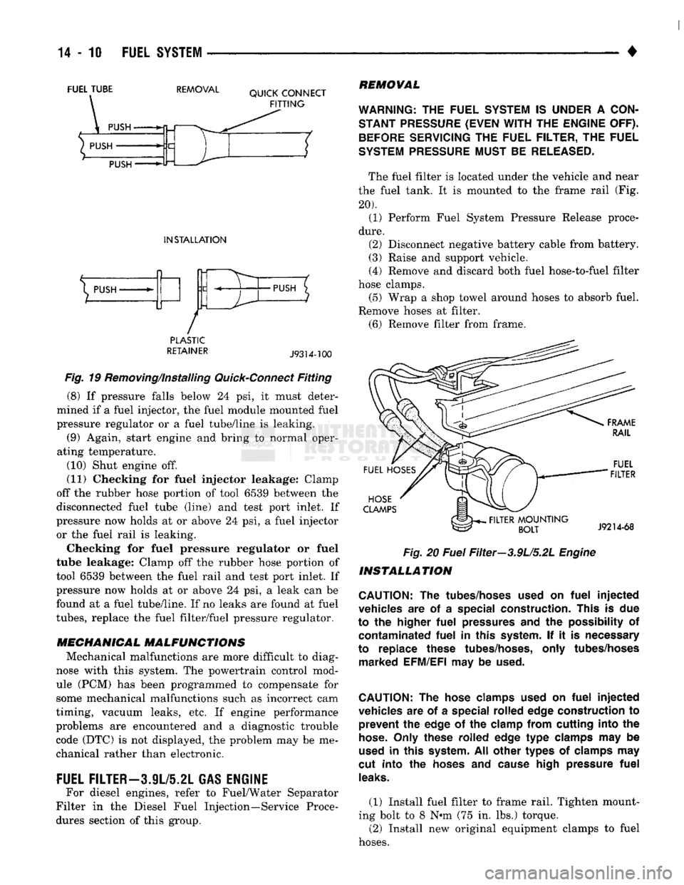
Fig. 19 Removing/Installing Quick-Connect Fitting (8) If pressure falls below 24 psi, it must deter
mined if a fuel injector, the fuel module mounted fuel
pressure regulator or a fuel tube/line is leaking. (9) Again, start engine and bring to normal oper
ating temperature.
(10) Shut engine off.
(11) Checking for fuel injector leakage: Clamp
off the rubber hose portion of tool 6539 between the
disconnected fuel tube (line) and test port inlet. If
pressure now holds at or above 24 psi, a fuel injector or the fuel rail is leaking.
Checking for fuel pressure regulator or fuel
tube leakage: Clamp off the rubber hose portion of
tool 6539 between the fuel rail and test port inlet. If
pressure now holds at or above 24 psi, a leak can be
found at a fuel tube/line. If no leaks are found at fuel
tubes,
replace the fuel filter/fuel pressure regulator.
MECHANICAL MALFUNCTIONS
Mechanical malfunctions are more difficult to diag
nose with this system. The powertrain control mod
ule (PCM) has been programmed to compensate for
some mechanical malfunctions such as incorrect cam
timing, vacuum leaks, etc. If engine performance
problems are encountered and a diagnostic trouble code (DTC) is not displayed, the problem may be me
chanical rather than electronic.
FUEL FILTER-3.9L/5.2L GAS ENGINE
For diesel engines, refer to Fuel/Water Separator
Filter in the Diesel Fuel Injection—Service Proce
dures section of this group.
REMOVAL
WARNING:
THE
FUEL
SYSTEM
IS
UNDER
A
CON
STANT
PRESSURE
(EVEN
WITH
THE
ENGINE
OFF).
BEFORE
SERVICING
THE
FUEL FILTER,
THE
FUEL
SYSTEM
PRESSURE
MUST
BE
RELEASED.
The fuel filter is located under the vehicle and near
the fuel tank. It is mounted to the frame rail (Fig.
20). (1) Perform Fuel System Pressure Release proce
dure.
(2) Disconnect negative battery cable from battery.
(3) Raise and support vehicle.
(4) Remove and discard both fuel hose-to-fuel filter
hose clamps. (5) Wrap a shop towel around hoses to absorb fuel.
Remove hoses at filter. (6) Remove filter from frame.
FUEL
HOSES
HOSE
CLAMPS
.
FILTER
MOUNTING
BOLT
FUEL
FILTER
J9214-68
Fig.
20
Fuel
Filter—3.9U5.2L
Engine
INSTALLATION
CAUTION:
The
tubes/hoses used
on
fuel
injected
vehicles
are of a
special construction. This
is due
to
the
higher
fuel
pressures
and the
possibility
of
contaminated
fuel
in
this system.
If it is
necessary
to replace these tubes/hoses, only tubes/hoses marked EFM/EFI
may be
used.
CAUTION:
The
hose clamps used
on
fuel
injected
vehicles
are of a
special rolled edge construction
to
prevent
the
edge
of the
clamp from cutting into
the
hose.
Only these rolled edge
type
clamps
may be
used
in
this system.
All
other types
of
clamps
may
cut into
the
hoses
and
cause high pressure
fuel
leaks.
(1) Install fuel filter to frame rail. Tighten mount
ing bolt to 8 N»m (75 in. lbs.) torque. (2) Install new original equipment clamps to fuel
hoses.
Page 856 of 1502
•
FUEL SYSTEM
14 - 37 used only on vehicles equipped with the 5.9L heavy
duty cycle (HDC) engine. Refer to Group 25, Emis
sion Control System for information.
EVAP CANISTER PURGE SOLENOID-PCM
OUTPUT
Refer to Group 25, Emission Control System. See
EVAP Canister Purge Solenoid.
FUEL INJECTORS-PCM
OUTPUT
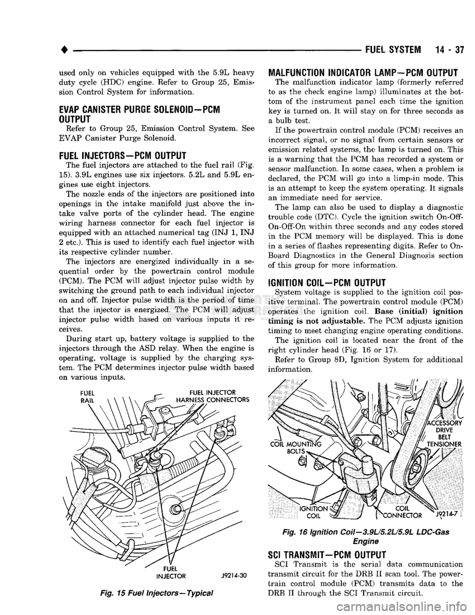
The fuel injectors are attached to the fuel rail (Fig.
15).
3.9L engines use six injectors. 5.2L and 5.9L en
gines use eight injectors. The nozzle ends of the injectors are positioned into
openings in the intake manifold just above the in
take valve ports of the cylinder head. The engine
wiring harness connector for each fuel injector is equipped with an attached numerical tag (INJ 1, INJ 2 etc.). This is used to identify each fuel injector with
its respective cylinder number. The injectors are energized individually in a se
quential order by the powertrain control module (PCM). The PCM will adjust injector pulse width by
switching the ground path to each individual injector
on and off. Injector pulse width is the period of time
that the injector is energized. The PCM will adjust injector pulse width based on various inputs it re
ceives. During start up, battery voltage is supplied to the
injectors through the ASD relay. When the engine is
operating, voltage is supplied by the charging sys
tem. The PCM determines injector pulse width based on various inputs.
FUEL
INJECTOR
J9214-30
Fig.
15
Fuel
injectors—Typical
MALFUNCTION INDICATOR LAMP-PCM OUTPUT
The malfunction indicator lamp (formerly referred
to as the check engine lamp) illuminates at the bot
tom of the instrument panel each time the ignition key is turned on. It will stay on for three seconds as a bulb test. If the powertrain control module (PCM) receives an
incorrect signal, or no signal from certain sensors or
emission related systems, the lamp is turned on. This
is a warning that the PCM has recorded a system or
sensor malfunction. In some cases, when a problem is
declared, the PCM will go into a limp-in mode. This
is an attempt to keep the system operating. It signals an immediate need for service. The lamp can also be used to display a diagnostic
trouble code (DTC). Cycle the ignition switch
On-Off-
On-Off-On within three seconds and any codes stored
in the PCM memory will be displayed. This is done
in a series of flashes representing digits. Refer to On-
Board Diagnostics in the General Diagnosis section
of this group for more information.
IGNITION COIL-PCM OUTPUT
System voltage is supplied to the ignition coil pos
itive terminal. The powertrain control module (PCM)
operates the ignition coil. Base (initial) ignition
timing is not adjustable. The PCM adjusts ignition
timing to meet changing engine operating conditions. The ignition coil is located near the front of the
right cylinder head (Fig. 16 or 17). Refer to Group 8D, Ignition System for additional
information.
Fig.
16 Ignition Coii-3.9U5.2U5.9L
LDC-Gas
Engine
SCI
TRANSMIT—PCM OUTPUT
SCI Transmit is the serial data communication
transmit circuit for the DRB II scan tool. The power- train control module (PCM) transmits data to the DRB II through the SCI Transmit circuit.
Page 873 of 1502
14-54 FUEL SYSTEM
• is good, replace the PCM. If terminal/pin-4 has a
short circuit to 12 volts +, correct this condition be
fore replacing the PCM.
CRANKSHAFT POSITION SENSOR TEST
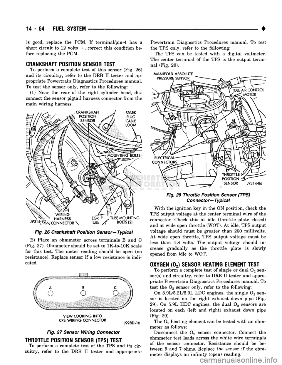
To perform a complete test of this sensor (Fig. 26)
and its circuitry, refer to the DRB II tester and ap
propriate Powertrain Diagnostics Procedures manual.
To test the sensor only, refer to the following: (1) Near the rear of the right cylinder head, dis
connect the sensor pigtail harness connector from the
main wiring harness.
Fig.
26 Crankshaft Position
Sensor—
Typical
(2) Place an ohmmeter across terminals B and C
(Fig. 27). Ohmmeter should be set to lK-to-lOK scale
for this test. The meter reading should be open (no
resistance). Replace sensor if a low resistance is indi
cated.
VIEW
LOOKING
INTO
CPS
WIRING
CONNECTOR
Fig.
27
Sensor
Wiring
Connector
THROTTLE POSITION SENSOR (TPS) TEST
To perform a complete test of the TPS and its cir
cuitry, refer to the DRB II tester and appropriate Powertrain Diagnostics Procedures manual. To test
the TPS only, refer to the following:
The TPS can be tested with a digital voltmeter.
The center terminal of the TPS is the output termi nal (Fig. 28).
AAANIFOLD
ABSOLUTE
Fig.
28
Throttle
Position
Sensor
(TPS)
Connector—
Typical
With the ignition key in the ON position, check the
TPS output voltage at the center terminal wire of the connector. Check this at idle (throttle plate closed) and at wide open throttle (WOT). At idle, TPS output
voltage should must be greater than 200 millivolts.
At wide open throttle, TPS output voltage must be
less than 4.8 volts. The output voltage should in
crease gradually as the throttle plate is slowly
opened from idle to WOT.
OXYGEN
(02)
SENSOR HEATING ELEMENT TEST
To perform a complete test of single or dual 02 sen-
sor(s) and circuitry, refer to DRB II tester and appro
priate Powertrain Diagnostics Procedures manual. To
test the 02 sensor only, refer to the following:
On 3.9L/5.2L/5.9L LDC engines, the single 02 sen
sor is located on the right exhaust down pipe (Fig.
29).
On 5.9L HDC engines, the dual 02 sensors are
located on each (left and right) exhaust down pipe (Fig. 29).
The 02 heating element can be tested with an ohm
meter as follows: Disconnect the 02 sensor connector. Connect the
ohmmeter test leads across the white wire terminals
of the sensor connector. Resistance should be be
tween 5 and 7 ohms. Replace the sensor if the ohm meter displays an infinity (open) reading.