1993 DODGE TRUCK tow
[x] Cancel search: towPage 6 of 1502
INTRODUCTION
INTRODUCTION
DESIGNATIONS,
LABELS/PLATES/DECALS,
CODES
AND DIMENSIONS/WEIGHTS .
CONTENTS
page
MEASUREMENT
AND TORQUE
... 1 SPECIFICATIONS
page
. 11
DESIGNATIONS, LABELS/PLATES/DECALS, CODES
AND
DIMENSIONS/WEIGHTS
INDEX
page
Engine
and
Transmission/Transfer
Case
Identification
2
Engine/Transmission/GVWR
4
Equipment
Identification
Plate
3
International
Vehicle Control
and
Display
Symbols
10
Major Component
Identification 3
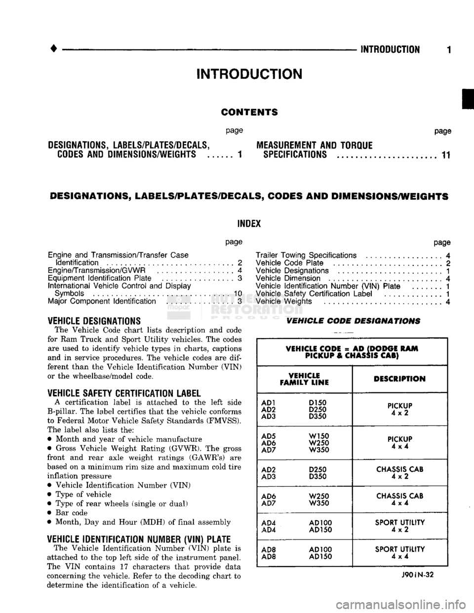
VEHICLE DESIGNATIONS The Vehicle Code chart lists description and code
for Ram Truck and Sport Utility vehicles. The codes are used to identify vehicle types in charts, captions
and in service procedures. The vehicle codes are
dif
ferent than the Vehicle Identification Number (VIN) or the wheelbase/model code.
VEHICLE SAFETY CERTIFICATION
LABEL
A certification label is attached to the left side
B-pillar. The label certifies that the vehicle conforms
to Federal Motor Vehicle Safety Standards (FMVSS).
The label also lists the: • Month and year of vehicle manufacture
• Gross Vehicle Weight Rating (GVWR). The gross
front and rear axle weight ratings (GAWR's) are
based on a minimum rim size and maximum cold tire inflation pressure Vehicle Identification Number (VIN)
Type of vehicle
Type of rear wheels (single or dual) Bar code
Month, Day and Hour (MDH) of final assembly
VEHICLE IDENTIFICATION NUMBER (VIN) PLATE The Vehicle Identification Number (VIN) plate is
attached to the top left side of the instrument panel.
The VIN contains 17 characters that provide data
concerning the vehicle. Refer to the decoding chart to
determine the identification of a vehicle.
page
Trailer
Towing Specifications
4
Vehicle Code Plate
2
Vehicle Designations
1
Vehicle Dimension
4
Vehicle
Identification
Number (VIN) Plate
1
Vehicle Safety
Certification
Label
............. 1
Vehicle Weights
4
VEHICLE CODE
DESIGNATIONS
VEHICLE CODE
= AD
(DODGE
RAM
PICKUP
&
CHASSIS
CAB)
VEHICLE
FAMILY LINE DESCRIPTION
AD1
D150
AD2
D250
AD3
D350
PICKUP
4x2
AD5
W150
AD6
W250
AD7
W350
PICKUP
4x4
AD2
D250
AD3
D350
CHASSIS
CAB
4x2
AD6
W250
AD7
W350
CHASSIS
CAB
4x4
AD4
AD100
AD4
AD150
SPORT
UTILITY
4x2
AD8
AD100
AD8 AD
150
SPORT
UTILITY
4x4
J90IN-32
Page 9 of 1502
4 INTRODUCTION
• VEHICLE DIMENSIONS
VEHICLE
FAMILY
WHEELBASE
AVAILABLE
CAB
TO
AXLE BODY
TYPE
SfANDAID
SODIES
AVAILABLE
VEHICLE
FAMILY
WHEELBASE
AVAILABLE
CAB
TO
AXLE BODY
TYPE
NOMINAL
LENGTH
(LOAD
SPACE
D
MENSIONS
(2)
VEHICLE
FAMILY
WHEELBASE
AVAILABLE
CAB
TO
AXLE BODY
TYPE
NOMINAL
LENGTH LENGTH MAX.
WIDTH
HEIGHT
VOLUME
AD-1
AD-5
2921
mm
(115
in) —
Sweptline
1981
mm
(6.5
ft)
1981
mm
(78
in)
1778 mm
(70
in)
485 mm
19.1
in) 1.71 m3
(60.35
ft3)
AD-1
AD-2
AD-3
AD-5
AD-6
AD-7
3327
mm
(131
in) —
Sweptline
2438 mm
(8
ft)
2489 mm
(98
in)
1778 mm
(70
in)
485 mm
(19.1
in)
2.15
m3
(75.8
ft3)
AD-2
AD-3
AD-7
3327
mm
(131
in)
1422 mm
(56
in)
Chassis
Cab
2438 mm
(8
ft)
—
— — —
AD-3
AD-7
3249 mm
(135
in)
1524 mm
(60
in)
Chassis
Cab
2896 mm
(9.5
ft) —
— — —
AD-3
4039 mm
(159
in)
2134 mm
(84
in)
Chassis
Cab
3810 mm
(12.5
ft)
—
— —
AD-4
2692
mm
(106
in)
Sport
Utility
4x2
—
1778 mm 1588 mm
(62.5
in)
1062 mm
(41.8
in)
2.99
m3
(105.8
ft3)
AD-8
2692
mm
(106
in)
Sport
Utility
4x4
—
1778 mm 1588 mm
(62.5
in)
1062 mm
(41.8
in)
2.99
m3
(105.8
ft3)
AD-1
3378 mm
(133
in) —
Sweptline
1981
mm
(6.5
ft)
1984 mm
(78.1
in)
1778 mm
(70
in)
485 mm
(19.1
in) 1.71 m3
(60.4
ft3)
AD-1
AD-2
AD-5
AD-6
3785 mm
(149
in) —
Sweptline
Club
Cab 2438 mm
(8
ft)
2489 mm
(98
in)
1778 mm
(70
in)
485 mm
(19.1
in)
2.15
M3
(75.8
ft3)
®
Driver seat
to
tailgate.
(2)
Based
on
S.A.E.
procedure
Jl
100. J901N-34
VEHICLE
WEIGHTS
The Vehicle Weights chart provides:
• The Gross Vehicle Weight Rating (GVWR),
• The payload
• The curb weight
for
each vehicle type/wheelbase
TRAILER
TOWING
SPECIFICATIONS
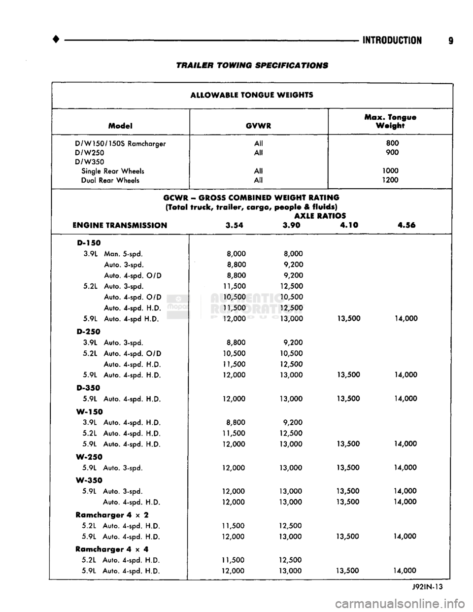
The Trailer Towing Specifications chart provides:
• The maximum trailer tongue weight
• The maximum trailer weight
• The maximum combined weight of the trailer/load/
towing vehicle with
a
specific engine/transmission/ axle combination.
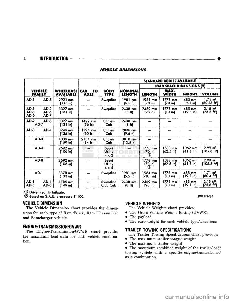
VEHICLE
DIMENSION
The Vehicle Dimension chart provides
the
dimen
sions
for
each type
of
Ram Truck, Ram Chassis Cab
and Ramcharger vehicle.
ENGINE/TRANSMISSION/GVWR
The Engine/Transmission/GVWR chart provides
the maximum load data
for
each vehicle combina tion.
Page 14 of 1502
TRAILER TOWING
SPECIFICATIONS
ALLOWABLE
TONGUE WEIGHTS Max. Tongue
Model
GVWR
Weight
D/W150/150S
Ramcharger All
800
D/W250
All
900
D/W350
Single
Rear Wheels All
1000
Dual Rear Wheels All
1200
GCWR
-
GROSS
COMBINED
WEIGHT RATING
(Total
truck,
trailer,
cargo,
people
&
fluids)
AXLE
RATIOS
ENGINE
TRANSMISSION
3.54
3.90 4.10
4.56
D-150 3.9L Man. 5-spd.
8,000 8,000
Auto. 3-spd.
8,800
9,200
Auto. 4-spd.
O/D
8,800
9,200
5.2L Auto. 3-spd.
11,500
12,500
Auto. 4-spd.
O/D
10,500
10,500
Auto. 4-spd.
H.D.
11,500
12,500
5.9L Auto. 4-spd
H.D.
12,000
13,000 13,500
14,000
D-250
3.9L Auto. 3-spd.
8,800
9,200
5.2L Auto. 4-spd.
O/D
10,500 10,500
Auto. 4-spd.
H.D.
11,500
12,500
5.9L Auto. 4-spd.
H.D.
12,000
13,000 13,500
14,000
D-350
5.9L Auto. 4-spd.
H.D.
12,000
13,000 13,500 14,000
W-150 3.9L Auto. 4-spd.
H.D.
8,800
9,200
5.2L Auto. 4-spd.
H.D.
11,500
12,500
5.9L Auto. 4-spd.
H.D.
12,000
13,000 13,500
14,000
W-250
5.9L Auto. 3-spd.
12,000
13,000 13,500 14,000
W-350
5.9L Auto. 3-spd.
12,000 13,000 13,500 14,000
Auto. 4-spd.
H.D.
12,000
13,000 13,500 14,000
Ramcharger
4x2
5.2L Auto. 4-spd.
H.D.
11,500 12,500
5.9L Auto. 4-spd.
H.D.
12,000 13,000 13,500 14,000
Ramcharger
4x4
5.2L Auto. 4-spd.
H.D.
11,500 12,500
5.9L Auto. 4-spd.
H.D.
12,000
13,000 13,500 14,000
Page 20 of 1502
•
• —
LUiRICATlON
AND
MAINTENANCE
0 - 1
CONTENTS
page
page
CHASSIS
AND
BODY
28
ENGINE MAINTENANCE
14
DRIVETRAIN
.,,, 22
GENERAL INFORMATION
1
GENERAL
INFORMATION INDEl
page
Classification
of
Lubricants
. 3
Components
Requiring
No
Lubrication
4
Fuel Requirements
. 2
Introduction
1
Lubrication
and
Replacement Parts Recommendation
3
page
Routine Maintenance
2
Starting
Assistance (Jump Starting)
9
Vehicle
Lifting
Recommendations
............ 10
Vehicle Noise
Control
2
Vehicle Towing Recommendations
11
INTRODUCTION
Lubrication and maintenance is divided into re
quired and recommended service tasks. The required service tasks must be completed to verify the emis
sion controls function correctly. The recommended
service tasks should be completed to maintain safety
and durability. This information will assist the service personnel
in providing maximum protection for each owner's
vehicle. Conditions can vary with individual driving habits.
It is necessary to schedule maintenance as a time in
terval as well as a distance interval. It is the owner's responsibility to determine the ap
plicable driving condition. Also to have the vehicle serviced according to the maintenance schedule, and
to pay for the necessary parts and labor. Vehicles with a Gross Vehicle Weight Rating
(GVWR) of 3 855 kg (8,500 lbs.) or less must conform
to light duty emission standards. Vehicles with a Gross Vehicle Weight Rating (GVWR) of 3 856 kg
(8,501 lbs.) or more must conform to heavy duty
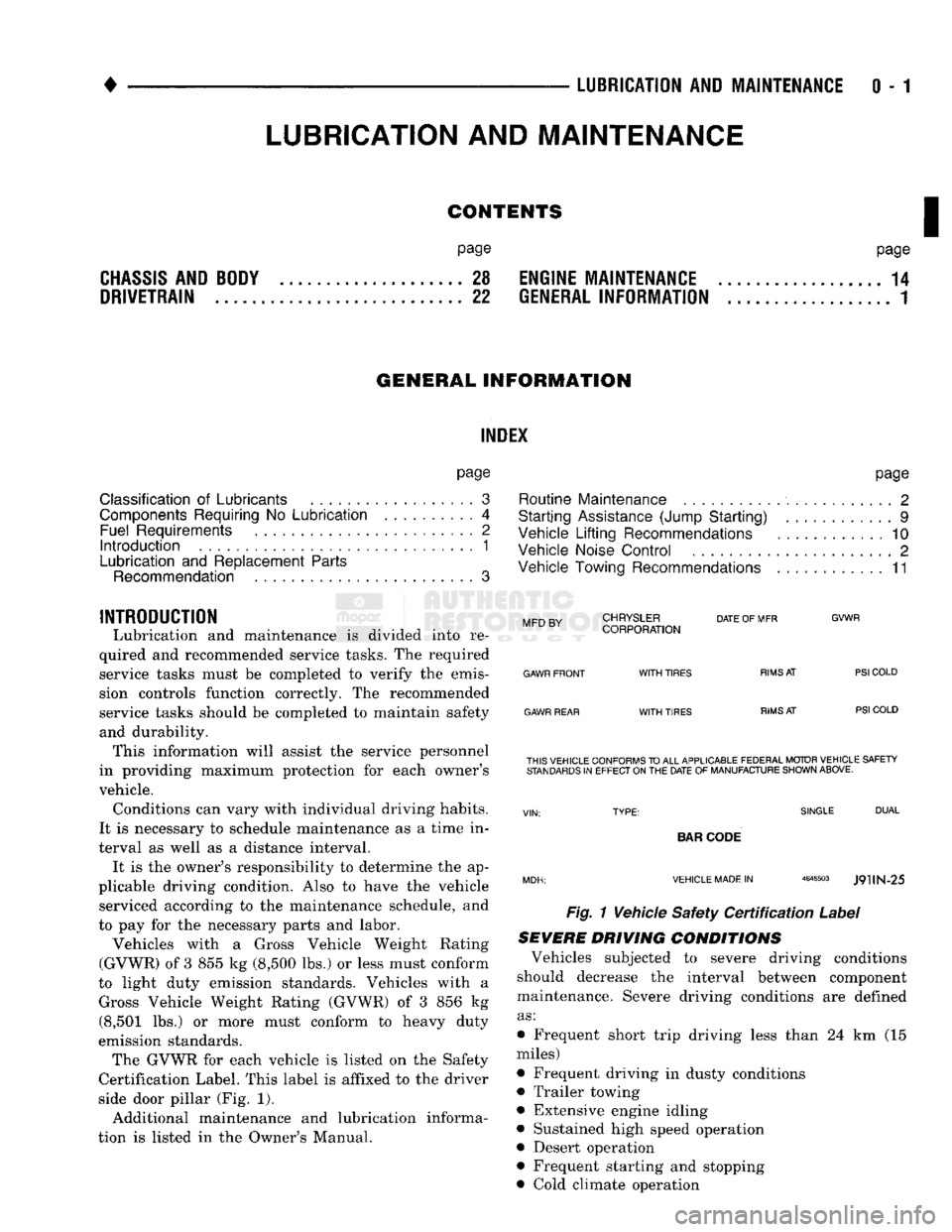
emission standards. The GVWR for each vehicle is listed on the Safety
Certification Label. This label is affixed to the driver
side door pillar (Fig. 1).
Additional maintenance and lubrication informa
tion is listed in the Owner's Manual.
Mm
rv
CHRYSLER
DATE
OF MFR
MFD BY CORPORATION
GVWR
GAWR FRONT
GAWR REAR
WITH
TIRES
WITH
TIRES
RIMS
AT
RIMS
AT
PSI
COLD
PSI
COLD THIS VEHICLE CONFORMS
TO
ALL APPLICABLE FEDERAL MOTOR VEHICLE SAFETY
STANDARDS
IN
EFFECT ON
THE
DATE
OF
MANUFACTURE SHOWN ABOVE.
SINGLE
DUAL
BAR
CODE
VEHICLE MADE
IN
4648503
J9UN-25
Fig. 1 Vehicle Safety
Certification
Label
SEVERE DRIVING
CONDITIONS
Vehicles subjected to severe driving conditions
should decrease the interval between component
maintenance. Severe driving conditions are defined
as:
• Frequent short trip driving less than 24 km (15
miles)
• Frequent driving in dusty conditions
• Trailer towing
• Extensive engine idling
• Sustained high speed operation
• Desert operation
• Frequent starting and stopping
• Cold climate operation
LUBRICATION
AND
MAINTENANCE
Page 28 of 1502
•
LUBRICATION AND MAINTENANCE
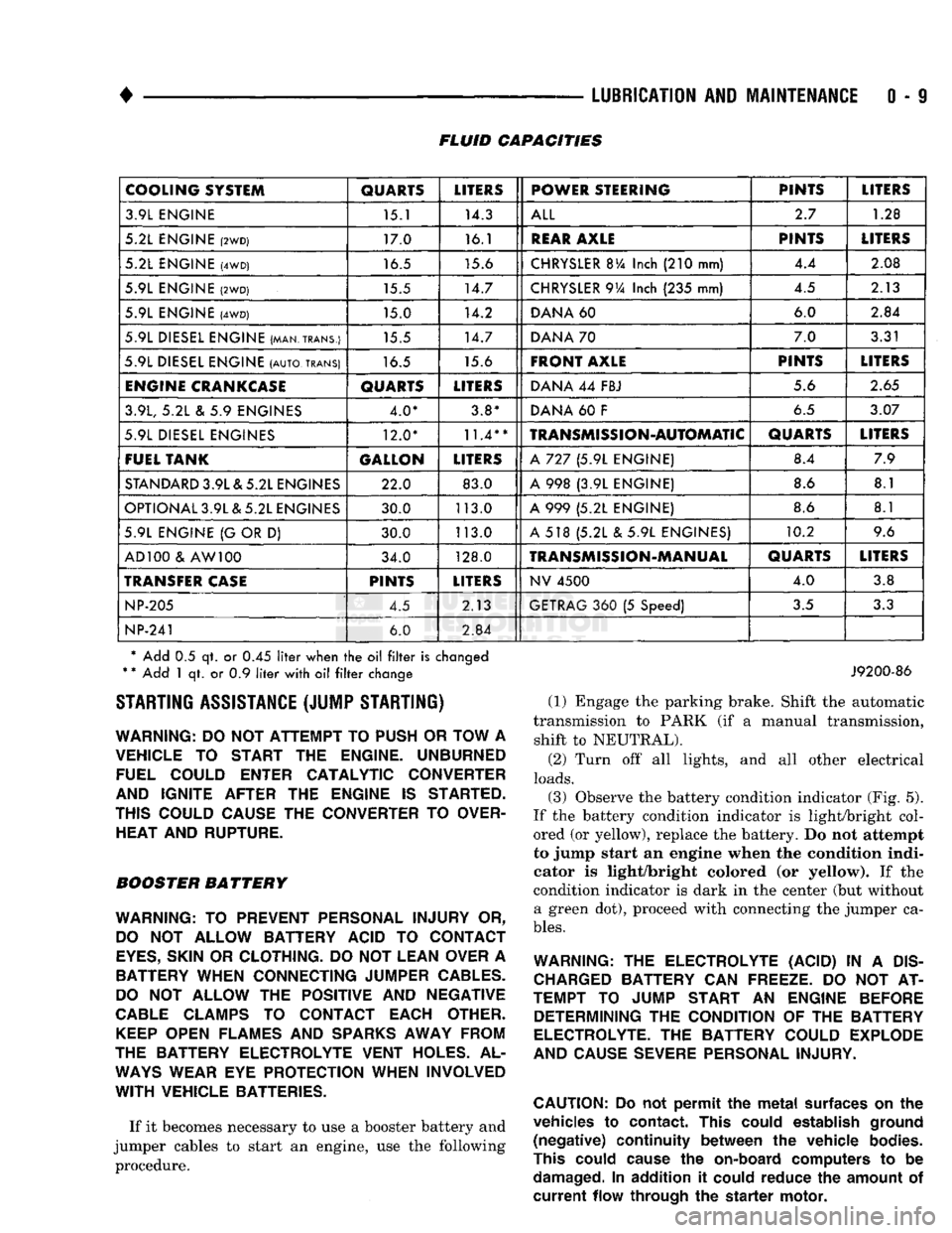
0 - 9 FLUID CAPACITIES
COOLING SYSTEM
QUARTS
LITERS
POWER STEERING PINTS
LITERS
3.9L ENGINE 15.1 14.3
ALL
2.7
1.28
5.2L ENGINE
(2WD)
17.0 16.1
REAR
AXLE
PINTS
LITERS
5.2L ENGINE
(4WD)
16.5 15.6
CHRYSLER
BVa
Inch
(210
mm) 4.4
2.08
5.9L ENGINE
(2WD)
15.5 14.7
CHRYSLER
9Va
Inch
(235
mm) 4.5
2.13
5.9L ENGINE
(4WD)
15.0 14.2
DANA
60 6.0
2.84
5.9L DIESEL ENGINE (MAN.TRANS.) 15.5 14.7
DANA
70 7.0
3.31
5.9L DIESEL ENGINE
(AUTO,
TRANS)
16.5 15.6
FRONT AXLE
PINTS
LITERS
ENGINE
CRANKCASE
QUARTS
LITERS
DANA
44
FBJ 5.6
2.65
3.9L,
5.2L & 5.9
ENGINES 4.0* 3.8*
DANA
60 F
6.5
3.07
5.9L DIESEL ENGINES 12.0*
11.4**
TRANSMISSION-AUTOMATIC
QUARTS
LITERS
FUEL TANK GALLON
LITERS
A
727 (5.9L
ENGINE) 8.4
7.9
STANDARD
3.9L & 5.2L ENGINES 22.0 83.0
A
998 (3.9L
ENGINE) 8.6
8.1
OPTIONAL 3.9L & 5.2L ENGINES 30.0 113.0
A
999 (5.2L
ENGINE) 8.6
8.1
5.9L ENGINE
{G
OR
D)
30.0 113.0
A
518 (5.2L & 5.9L
ENGINES) 10.2
9.6
AD 100
&
AW 100 34.0 128.0
TRANSMISSION-MANUAL
QUARTS
LITERS
TRANSFER
CASE
PINTS
LITERS
NV
4500
4.0
3.8
NP-205
4.5 2.13
GETRAG
360 (5
Speed)
3.5
3.3
NP-241
6.0
2.84
* Add
0.5 qt. or 0.45
liter
when
the oil filter
is
changed
*
*
Add
1 qt. or 0.9
liter
with
oil filter
change STARTING ASSISTANCE (JUMP STARTING)
WARNING:
DO NOT
ATTEMPT
TO
PUSH
OR
TOW
A
VEHICLE
TO
START
THE
ENGINE. UNBURNED FUEL COULD ENTER CATALYTIC CONVERTER
AND IGNITE AFTER
THE
ENGINE
IS
STARTED.
THIS COULD CAUSE
THE
CONVERTER
TO
OVER HEAT AND RUPTURE.
BOOSTER BATTERY
WARNING:
TO
PREVENT PERSONAL INJURY
OR,
DO
NOT
ALLOW BATTERY ACID
TO
CONTACT
EYES,
SKIN
OR
CLOTHING.
DO NOT
LEAN OVER
A
BATTERY WHEN CONNECTING JUMPER
CABLES.
DO
NOT
ALLOW
THE
POSITIVE
AND
NEGATIVE
CABLE
CLAMPS
TO
CONTACT EACH OTHER.
KEEP
OPEN FLAMES
AND
SPARKS
AWAY FROM
THE BATTERY ELECTROLYTE VENT HOLES.
AL
WAYS
WEAR
EYE
PROTECTION WHEN INVOLVED
WITH
VEHICLE BATTERIES.
If it becomes necessary to use a booster battery and
jumper cables to start an engine, use the following procedure.
J9200-86
(1) Engage the parking brake. Shift the automatic
transmission to PARK (if a manual transmission, shift to NEUTRAL).
(2) Turn off all lights, and all other electrical
loads.
(3)
Observe the battery condition indicator (Fig. 5).
If the battery condition indicator is light/bright col
ored (or yellow), replace the battery. Do not attempt
to jump start an engine when the condition indi
cator is light/bright colored (or yellow). If the
condition indicator is dark in the center (but without a green dot), proceed with connecting the jumper ca
bles.
WARNING:
THE
ELECTROLYTE (ACID)
IN A
DIS
CHARGED
BATTERY
CAN
FREEZE.
DO NOT AT
TEMPT
TO
JUMP START
AN
ENGINE BEFORE DETERMINING
THE
CONDITION
OF THE
BATTERY
ELECTROLYTE.
THE
BATTERY COULD EXPLODE
AND CAUSE SEVERE PERSONAL INJURY.
CAUTION:
Do not
permit
the
metal
surfaces
on the
vehicles
to
contact.
This
could
establish
ground
(negative)
continuity
between
the
vehicle
bodies.
This
could
cause
the
on-board
computers
to be
damaged.
In
addition
it
could
reduce
the
amount
of
current
flow
through
the
starter
motor.
Page 30 of 1502

LUBRICATION
AND
MAINTENANCE
0-11
J
DRIVE-ON
HOIST
I
FRAME
CONTACT
HOIST
TWIN
POST
CHASSIS
HOIST
FLOOR
JACK
RROOD30
Fig.
8 Correct Vehicle Lifting
Locations
An axle tube
A body side sill
A steering linkage component
A drive shaft
The engine or transmission oil pan
The fuel tank
• A front suspension arm Use the correct frame rail lifting locations only
(Fig. 8).
HOIST A vehicle can be lifted with:
• A single-post, frame-contact hoist
• A twin-post, chassis hoist
• A ramp-type, drive-on hoist
When a frame-contact type hoist is used, verify
that the lifting pads are positioned properly (Fig. 8).
WARNING:
WHEN
A
SERVICE
PROCEDURE
RE
QUIRES
THE
REMOVAL
OF
THE
REAR
AXLE,
FUEL
TANK,
OR
SPARE
TIRE,
EITHER:
• PLACE ADDITIONAL WEIGHT ON THE REAR
END OF THE VEHICLE
« ATTACH THE VEHICLE TO THE HOIST
« PLACE JACK STANDS UNDER THE VEHICLE
FOR SUPPORT TO PREVENT TIPPING WHEN
THE CENTER OF BALANCE CHANGES
4WD VEHICLES A standard hoist can be used to lift a 4WD vehicle.
The hoist should be inspected for adequate clearance. The lift arms, pads or ramps should be adjusted to
ensure that there is adequate clearance (Fig. 9).
ADJUSTMENT
PAD
ii 7
MAINTAIN
CLEARANCE
HOIST
ARM
RK44
Fig.
9 Lifting 4WD Vehicle
With
Single-Post
Hoist—
Typical
When a twin-post hoist is used, a 4 x 4 x 12-inch
wood spacer also could be required. Place the wood spacer under the front axle (opposite the differential
housing). This will maintain balance and level lift ing.
CAUTION:
The
block
that
is
used must
be
secured in
a
safe manner. This
will
ensure
that
it
will
not un
balance
the
vehicle.
VEHICLE
TOWING
RECOMMENDATIONS
When it is necessary to tow a Ram Truck, the rec
ommended method is either:
• the sling-type, rear-end raised towing method; or
• the wheel-lift towing method with a tow dolly lo
cated under the front wheels. A vehicle with flat-bed hauling equipment can also
be used to transport a disabled vehicle.
SLING-TYPE
FLAT
BED
RR0OD29
Fig.
10 Tow Vehicles
With
Approved
Equipment
Page 31 of 1502

0 - 12
LUBRICATION
AND
MAINTENANCE
• A vehicle equipped with SAE approved sling-type
towing equipment can be used (Fig. 10). However,
many vehicles are equipped with air dams, spoilers, and/or ground effect panels. In this case a wheel-lift
towing vehicle or a flat-bed hauling vehicle is recom mended (Fig. 10). If a flat bed device is used, the ap
proach angle should not exceed 15 degrees.
GROUND CLEARANCE The lifted wheels of the disabled vehicle should be
a minimum of 10 cm (4 in.) off the ground. Make
sure there is enough clearance at the opposite end.
This is critical when towing over rough terrain. If necessary, the rear ground clearance can be increased by removing the wheels from the lifted end
and then towing with the lifted end closer to the
ground. If the rear wheels are removed, secure the
brake drums. A 20 cm (8 in.) ground clearance must
be maintained between brake drums or rotors and the ground.
SAFETY PRECAUTIONS The following safety precautions must be consid
ered when preparing for and during a vehicle towing operation:
• Remove exhaust pipe tips that interfere with the
tow sling and crossbar • Padding should be placed between the tow sling/
crossbar and any painted surfaces
• If the vehicle is damaged, secure the loose and pro
truding parts
• Always use a safety chain system that is indepen dent of the lifting and towing equipment
• When placing tow hooks on the rear axle, position them so they do not damage the brake tubing or
hoses
• Do not allow any of the towing equipment to con
tact the fuel tank
• Do not tow the vehicle by connecting to the front
or rear shock absorbers
• The operator should not go under a vehicle while
it is lifted by the towing equipment. The vehicle
should first be supported by safety stands
• Do not allow passengers in a vehicle being towed
• Observe all state and local laws involving warning signals, night illumination, speed, etc.
• Do not exceed a towing speed of 48 km/h (30 mph)
• Avoid towing distances of more than 24 km (15
miles) whenever possible • Do not attach tow chains or a tow sling to a
bumper, the steering linkage, the universal joints, or a drive shaft
REAR-END RAISED TOWING It is recommended that the rear-end raised towing
method be used. Vehicles can be towed with the front
wheels on the ground for extended distances at speeds not exceeding 48 km/h (30 mph) (Fig. 11). (1) Attach the J-hooks around the axle shaft tubes
outboard of the rear springs. (2) Position and center the sling under and for
ward of the rear bumper. (3) Attach safety chains (with pads) at each end of
the rear bumper.
(4) Turn the ignition switch to the OFF position to
unlock the steering wheel. (5) Clamp the steering wheel with the front wheels
in the straight ahead position.
CAUTION:
Do not use the steering
column
lock
to
secure
front
wheel
in the straight-ahead
position.
(6) Shift the transmission to NEUTRAL.
POSITION CENTER BAR FORWARD
OF
BUMPER
-
/
J-HOOKS OUTBOARD
OF
SPRINGS
RN967A
Fig. 11 Rear-End
Raised
Towing
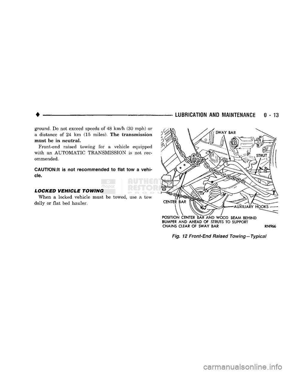
FRONT'END RAISED TOWING If a vehicle cannot be towed from the rear, the
front-end raised towing method normally can be
used (Fig. 12). (1) Center the sling with the bumper and position
it at the frame front crossmember.
CAUTION:
Use tow
chains
with
J-hooks
for
con
necting
to the
disabled
vehicle's
lower
suspension
arms.
Never use
T-hooks.
(2) Route the J-hooks and tow chains over the
steering linkage outboard of the coil spring.
(3) Attach the J-hooks to the outer end of the
lower suspension arms.
(4) Raise the vehicle.
(5.) Attach the safety chains to the disabled vehicle
at the frame rails.
Vehicles equipped with a MANUAL TRANSMIS
SION can be towed with the rear wheels on the
Page 32 of 1502
•
LUBRICATION
AND
MAINTENANCE
0 - 13 ground. Do not exceed speeds of 48 km/h (30 mph) or
a distance of 24 km (15 miles). The transmission
must be in neutral.
Front-end raised towing for a vehicle equipped
with an AUTOMATIC TRANSMISSION is not rec ommended.
CAUTION:lt
is not
recommended
to
flat
tow a
vehi
cle.
LOCKED
VEHICLE
TOWING
When a locked vehicle must be towed, use a tow
dolly or flat bed hauler.
POSITION
CENTER
BAR
AND
WOOD
BEAM
BEHIND
BUMPER
AND
AHEAD
OF
STRUTS
TO
SUPPORT
CHAINS CLEAR
OF
SWAY
BAR RN966
Fig.
12 Front-End
Raised
Towing—Typical