1993 DODGE TRUCK headliner
[x] Cancel search: headlinerPage 1385 of 1502
23
- 2
BODY COMPONENTS
•
EXPORT
LABEL
VEHICLE ORIGIN
LABEL
NATIONAL
SAFETY MARK
(CANADA) B-PILLAR
GLASS
EXHAUST
GAS
WARNING DECAL
UNLEADED/DIESEL FUEL LABEL
(U.S.)
EXHAUST EMISSION STANDARDS-CALIF.
(MODELS
30 AND 60)
EXHAUST
EMISSION
STADARDS-CALIF. (RAMCHARGER) UNLEADED/DIESEL
FUEL LABEL (CANADA)
J9123-408
Fig.
2
Exterior
Labels
&
Decals
ARM
BRACKET
NOISE
CERTIFICATION
LABEL
UOVER
10,000
LBS)5 SNOW
PLOW
TRANSMISSION
CAUTION HEADLINER
LABEL
TRANSFER
CASE
SHIFT
LABEL
(4WD)
SUN
VISOR
REAR
VIEW
MIRROR SCREW
*
BRACKET
J9123-410
Fig.
3
Sunvisor
Rear
Labels
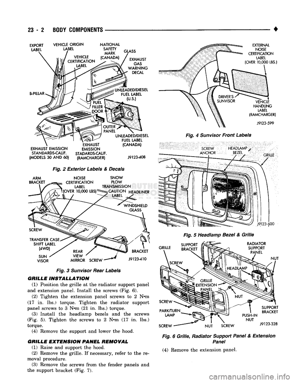
GRILLE INSTALLATION
(1) Position
the
grille
at the
radiator support panel
and extension panel. Install
the
screws
(Fig. 6).
(2) Tighten
the
extension panel screws
to 2 N»m
(17
in. lbs.)
torque. Tighten
the
radiator support
panel screws
to 3 Nnn (21 in. lbs.)
torque. (3) Install
the
headlamp bezels
and the
screws
(Fig.
5).
Tighten
the
screws
to 2 Nnn (17 in. lbs.)
torque. (4) Remove
the
support
and
lower
the
hood.
GRILLE EMTENSION PANEL REMOVAL (1) Raise
and
support
the
hood.
(2) Remove
the
grille.
If
necessary, refer
to the re
moval procedure. (3) Remove
the
screws from
the
fender panels
and
the support bracket
(Fig. 7).
EXTERNAL
NOISE
CERTIFICATION
LABEL
(OVER
10,000
LBS.)
VEHICLE
HANDLING
LABEL
(RAMCHARGER)
J9123-599
Fig.
4
Sunvisor
Front
Labels
SCREW
ANCHOR
HEADIAMP
BEZEL
•
GRILLE
J9123-600
Fig.
5
Headlamp
Bezel
&
Grille
GRILLE RADIATOR
SUPPORT PANEL
NUT
PUSH-IN
NUT
SCREW
NUT
SCREW SUPPORT
BRACKET
J9123-328
Fig.
6
Grille,
Radiator
Support Panel
&
Extension
Panel
(4) Remove
the
extension panel.
Page 1403 of 1502
23
- 20
BODY COMPONENTS
•
Fig.
52
Cargo
Box
Side
Panel
Braces
ROOF
VENT—RAMCHARGER
WENT
COWER
REMOVAL
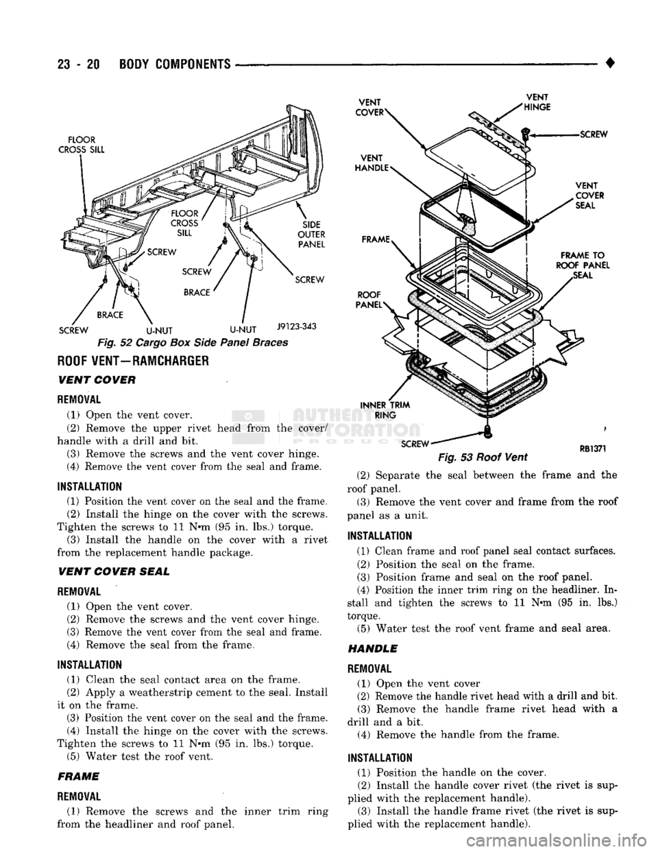
(1) Open the vent cover.
(2) Remove the upper rivet head from the cover/
handle with a drill and bit. (3) Remove the screws and the vent cover hinge.
(4) Remove the vent cover from the seal and frame.
INSTALLATION
(1) Position the vent cover on the seal and the frame. (2) Install the hinge on the cover with the screws.
Tighten the screws to 11 N-m (95 in. lbs.) torque.
(3) Install the handle on the cover with a rivet
from the replacement handle package.
WENT
COWER
SEAL
REMOVAL
(1) Open the vent cover.
(2) Remove the screws and the vent cover hinge.
(3) Remove the vent cover from the seal and frame.
(4) Remove the seal from the frame.
INSTALLATION
(1) Clean the seal contact area on the frame.
(2) Apply a weatherstrip cement to the seal. Install
it on the frame. (3) Position the vent cover on the seal and the frame.
(4) Install the hinge on the cover with the screws.
Tighten the screws to 11 N-m (95 in. lbs.) torque. (5) Water test the roof vent.
FRAME
REMOVAL
(1) Remove the screws and the inner trim ring
from the headliner and roof panel.
Fig.
53
Roof
Vent
(2) Separate the seal between the frame and the
roof panel. (3) Remove the vent cover and frame from the roof
panel as a unit.
INSTALLATION
(1) Clean frame and roof panel seal contact surfaces. (2) Position the seal on the frame.
(3) Position frame and seal on the roof panel.
(4) Position the inner trim ring on the headliner. In
stall and tighten the screws to 11 N-m (95 in. lbs.)
torque.
(5) Water test the roof vent frame and seal area.
HANDLE
REMOVAL
(1) Open the vent cover
(2) Remove the handle rivet head with a drill and bit.
(3) Remove the handle frame rivet head with a
drill and a bit. (4) Remove the handle from the frame.
INSTALLATION
(1) Position the handle on the cover. (2) Install the handle cover rivet (the rivet is sup
plied with the replacement handle).
(3) Install the handle frame rivet (the rivet is sup
plied with the replacement handle).
Page 1418 of 1502
•
BODY
COMPONENTS
23 - 35
CAB/BODY
INTERIOR COMPONENTS
INDEX
page
Carpets
and
Floor Mats
51
Floor Console
and
Rear Storage Tray
.........
50
Front Seats
38
Headliners
48
Instrument
Panel
35
page
Interior
Trim
Panels
. 42
Rear
Seats
41
Shoulder
Belts/Lap Belt/Buckles
45
Spare
Tire
Carrier
45
INSTRUMENT
PANEL INSTRUMENT CLUSTER BEZEL
REMOVAL
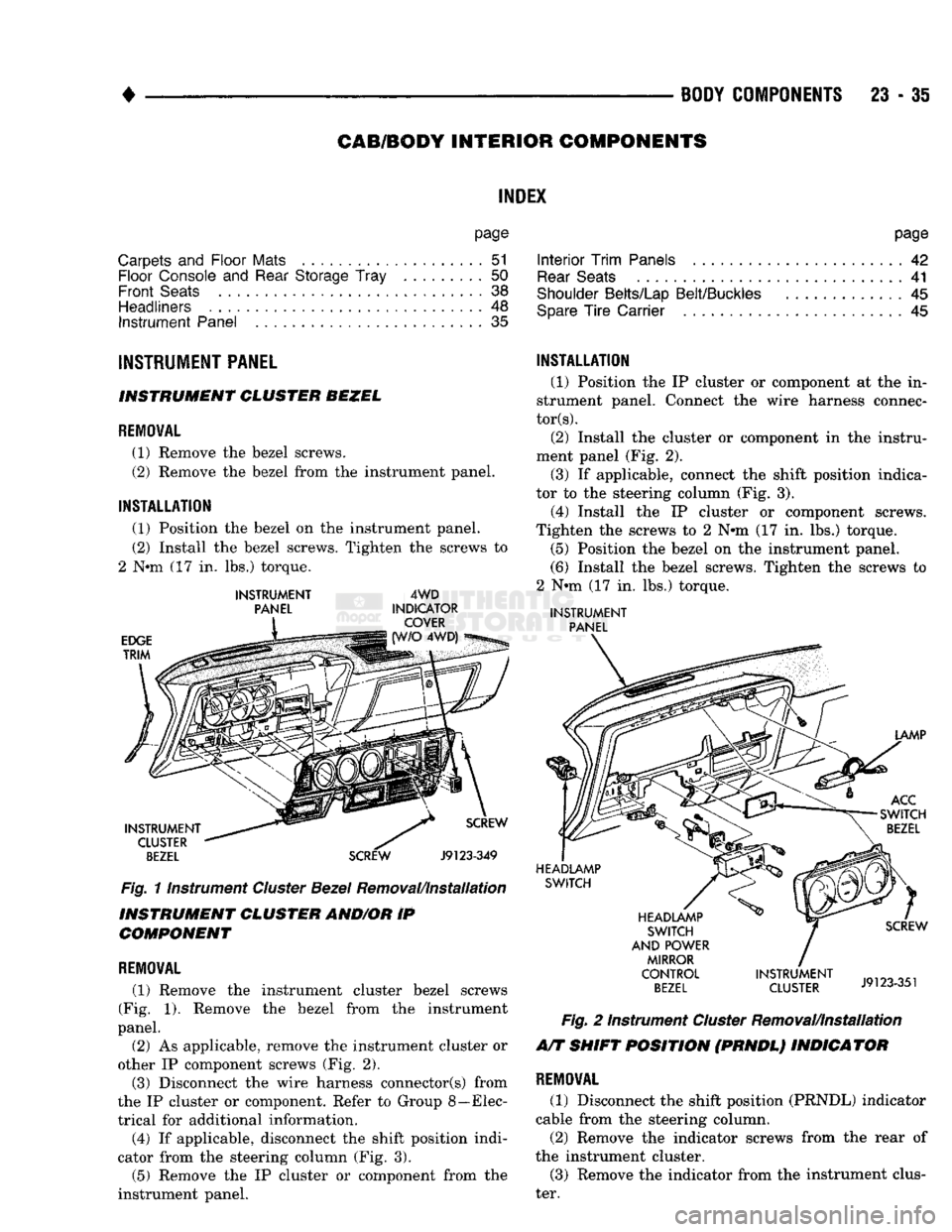
(1) Remove
the
bezel screws.
(2) Remove
the
bezel from
the
instrument panel.
INSTALLATION
(1) Position
the
bezel
on the
instrument panel.
(2) Install
the
bezel screws. Tighten
the
screws
to
2
Nnn (17 in. lbs.)
torque.
INSTRUMENT
PANEL
EDGE
TRIM
4WD
INDICATOR COVER 4WD)
INSTRUMENT CLUSTER
BEZEL
SCREW
Fig.
11nstrument
Cluster
Bezel
Removal/Installation
INSTRUMENT CLUSTER AND/OR
IP
COMPONENT
REMOVAL
(1) Remove
the
instrument cluster bezel screws
(Fig.
1).
Remove
the
bezel from
the
instrument
panel.
(2)
As
applicable, remove
the
instrument cluster
or
other
IP
component screws
(Fig. 2).
(3) Disconnect
the
wire harness connector(s) from
the
IP
cluster
or
component. Refer
to
Group 8—Elec
trical
for
additional information. (4)
If
applicable, disconnect
the
shift position indi
cator from
the
steering column
(Fig. 3).
(5) Remove
the IP
cluster
or
component from
the
instrument panel.
INSTALLATION
(1) Position
the IP
cluster
or
component
at the in
strument panel. Connect
the
wire harness connec
tors).
(2) Install
the
cluster
or
component
in the
instru
ment panel
(Fig. 2).
(3)
If
applicable, connect
the
shift position indica
tor
to the
steering column
(Fig. 3).
(4) Install
the IP
cluster
or
component screws.
Tighten
the
screws
to 2 N#m (17 in. lbs.)
torque. (5) Position
the
bezel
on the
instrument panel.
(6) Install
the
bezel screws. Tighten
the
screws
to
2
Nnn (17 in. lbs.)
torque.
INSTRUMENT
PANEL
LAMP
ACC
SWITCH
BEZEL
HEADLAMP SWITCH
HEADLAMP SWITCH
AND POWER MIRROR
CONTROL
BEZEL
SCREW
INSTRUMENT
J9123351
CLUSTER
J9123-351
Fig.
2
Instrument
Cluster
Removal/Installation
A/T SHIFT POSITION (PRNDL) INDICATOR
REMOVAL
(1) Disconnect
the
shift position (PRNDL) indicator
cable from
the
steering column.
(2) Remove
the
indicator screws from
the
rear
of
the instrument cluster. (3) Remove
the
indicator from
the
instrument clus
ter.
Page 1431 of 1502
23
- 48
BODY COMPONENTS
JUMP SEAT LAP BELT/BUCKLE
REMOVAL
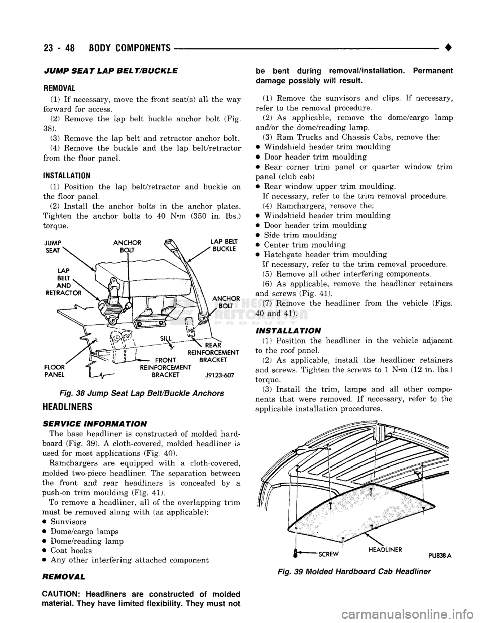
(1) If necessary, move the front seat(s) all the way
forward for access. (2) Remove the lap belt buckle anchor bolt (Fig.
38).
(3) Remove the lap belt and retractor anchor bolt.
(4) Remove the buckle and the lap belt/retractor
from the floor panel.
INSTALLATION
(1) Position the lap belt/retractor and buckle on
the floor panel.
(2) Install the anchor bolts in the anchor plates.
Tighten the anchor bolts to 40 N*m (350 in. lbs.)
torque.
Fig.
38
Jump
Seat
Lap
Belt/Buckle
Anchors
HEADLINERS
SERVICE INFORMATION
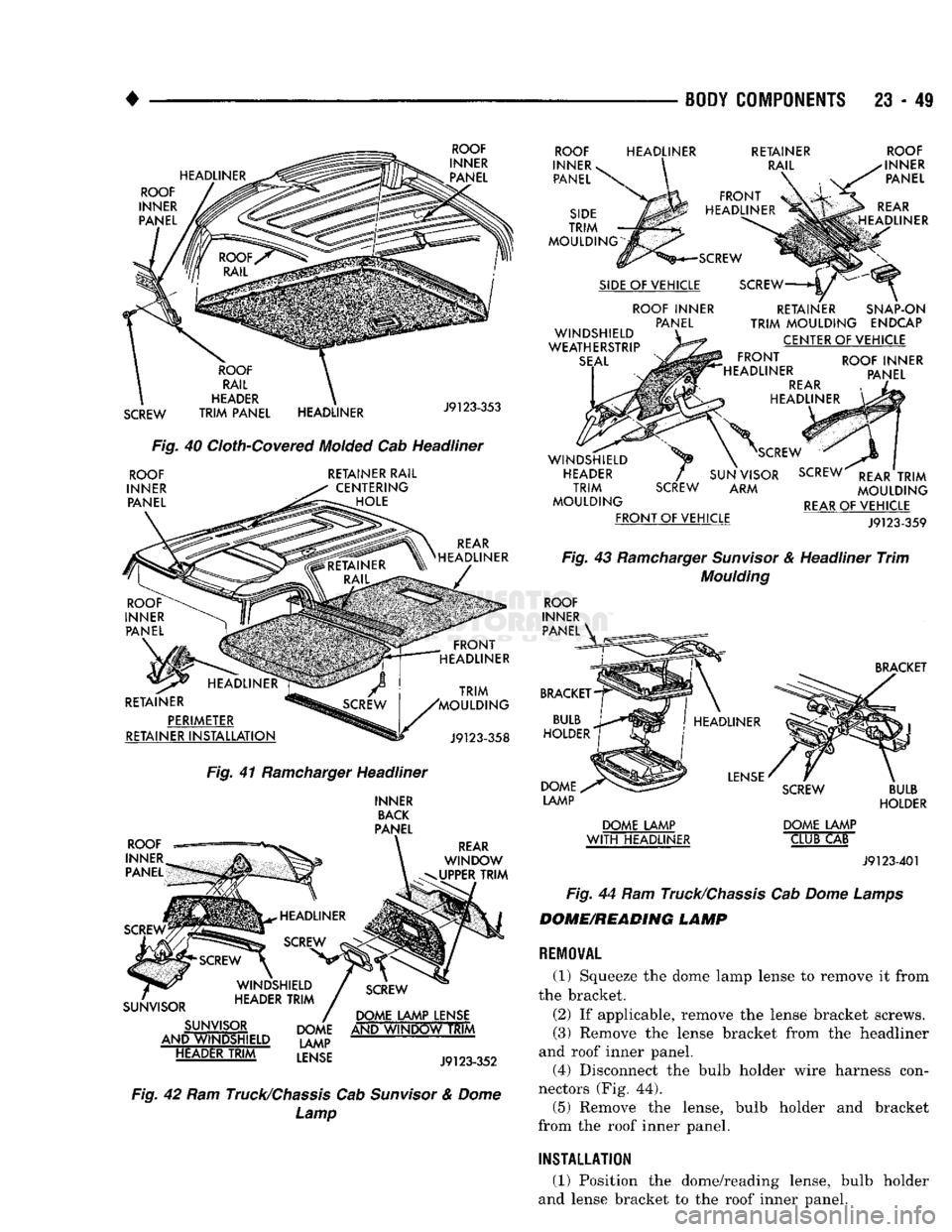
The base headliner is constructed of molded hard-
board (Fig. 39). A cloth-covered, molded headliner is
used for most applications (Fig, 40).
Ramchargers are equipped with a cloth-covered,
molded two-piece headliner. The separation between
the front and rear headliners is concealed by a
push-on trim moulding (Fig. 41).
To remove a headliner, all of the overlapping trim
must be removed along with (as applicable):
• Sunvisors
• Dome/cargo lamps • Dome/reading lamp
• Coat hooks
• Any other interfering attached component
REMOVAL be bent during removal/installation. Permanent
damage
possibly
will
result.
(1) Remove the sunvisors and clips. If necessary,
refer to the removal procedure. (2) As applicable, remove the dome/cargo lamp
and/or the dome/reading lamp.
(3) Ram Trucks and Chassis Cabs, remove the:
• Windshield header trim moulding
• Door header trim moulding
• Rear corner trim panel or quarter window trim
panel (club cab) • Rear window upper trim moulding.
If necessary, refer to the trim removal procedure.
(4) Ramchargers, remove the:
• Windshield header trim moulding
• Door header trim moulding
• Side trim moulding
• Center trim moulding
• Hatchgate header trim moulding
If necessary, refer to the trim removal procedure. (5) Remove all other interfering components.
(6) As applicable, remove the headliner retainers
and screws (Fig. 41).
(7) Remove the headliner from the vehicle (Figs.
40 and 41).
INSTALLATION
(1) Position the headliner in the vehicle adjacent
to the roof panel.
(2) As applicable, install the headliner retainers
and screws. Tighten the screws to 1 N*m (12 in. lbs.)
torque. (3) Install the trim, lamps and all other compo
nents that were removed. If necessary, refer to the applicable installation procedures.
Fig.
39
Molded
Hardboard Cab Headliner
CAUTION:
Headliners
are
constructed
of
molded
material. They have limited flexibility. They must
not
Page 1432 of 1502
•
^ ^ —
BODY COMPONENTS
23 - 49
HEADLINER ROOF
INNER PANEL
ROOF
INNER PANEL
SCREW
ROOF
RAIL
HEADER
TRIM
PANEL HEADLINER
J9123-353
Fig.
40
Cloth-Covered
Molded
Cab Headliner
ROOF
INNER PANEL RETAINER RAIL
CENTERING HOLE
REAR
HEADLINER
RETAINER PERIMETER
RETAINER
INSTALLATION
TRIM
'MOULDING
J9123-358
Fig.
41
Ramcharger
Headliner
INNER
BACK
PANEL
ROOF
—
INNER
PANEL
REAR
WINDOW
UPPER
TRIM
SUNVISOR SUNVISOR
AND WINDSHIELD HEADER
TRIM
DOME LAMP LENSE
DOME AND
WINDOW
TRIM
LAMP
LENSE
J9l
23-352
Fig.
42 Ram
Truck/Chassis
Cab
Sunvisor
&
Dome
Lamp
ROOF
INNER
v
PANEL
SIDE
TRIM
MOULDING
HEADLINER
RETAINER
RAIL
FRONT
HEADLINER
SCREW
SIDE
OF VEHICLE ROOF INNER PANEL
WINDSHIELD
WEATHERSTRIP
SEAL
ROOF
INNER PANEL
REAR
HEADLINER
SCREW
RETAINER SNAP-ON
TRIM
MOULDING
ENDCAP CENTER OF VEHICLE
FRONT
HEADLINER
REAR
HEADLINER ROOF INNER
PANEL WINDSHIELD
HEADER
TRIM
MOULDING
FRONT
OF VEHICLE
SCREW
SCREW
SUN VISOR SCREW
REAR
TRIM
ARM
MOULDING
REAR
OF VEHICLE
J9123-359
Fig.
43
Ramcharger
Sunvisor
& Headliner
Trim
Moulding
ROOF
INNER PANEL
BRACKET
BULB
HOLDER DOME
LAMP
BRACKET
HEADLINER
LENSE
DOME LAMP
WITH
HEADLINER
SCREW
DOME LAMP CLUB CAB
BULB
HOLDER
J9123-401
Fig.
44 Ram
Truck/Chassis
Cab
Dome
Lamps
DOME/READING LAMP
REMOVAL
(1) Squeeze the dome lamp lense to remove it from
the bracket.
(2) If applicable, remove the lense bracket screws.
(3) Remove the lense bracket from the headliner
and roof inner panel. (4) Disconnect the bulb holder wire harness con
nectors (Fig. 44). (5) Remove the lense, bulb holder and bracket
from the roof inner panel.
INSTALLATION
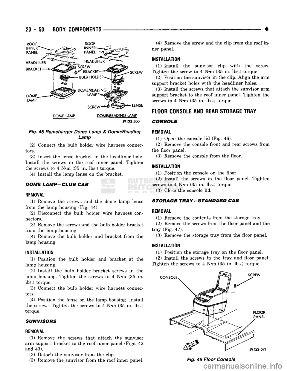
(1) Position the dome/reading lense, bulb holder
and lense bracket to the roof inner panel.
Page 1433 of 1502
23
- 50 BODY COMPONENTS — < ^ ^ • •
DOME LAMP DOME/READING LAMP
J9123-400
Fig.
45
Ramcharger
Dome Lamp
&
Dome/Reading Lamp (2) Connect
the
bulb holder wire harness connec
tors.
(3) Insert
the
lense bracket
in the
headliner hole.
Install
the
screws
in the
roof inner panel. Tighten
the screws
to 4 N#m (35 in. lbs.)
torque.
(4) Install
the
lamp lense
on the
bracket.
DOME LAMP-CLUB
CAB
REMOVAL
(1) Remove
the
screws
and the
dome lamp lense
from
the
lamp housing
(Fig. 44).
(2) Disconnect
the
bulb holder wire harness con
nectors.
(3) Remove
the
screws
and the
bulb holder bracket
from
the
lamp housing. (4) Remove
the
bulb holder
and
bracket from
the
lamp housing.
INSTALLATION
(1) Position
the
bulb holder
and
bracket
at the
lamp housing.
(2) Install
the
bulb holder bracket screws
in the
lamp housing. Tighten
the
screws
to 4 N°m (35 in.
lbs.) torque.
(3) Connect
the
bulb holder wire harness connec
tors.
(4) Position
the
lense
on the
lamp housing. Install
the screws. Tighten
the
screws
to 4 N#m (35 in. lbs.)
torque.
SUNVISORS
REMOVAL
(1) Remove
the
screws that attach
the
sunvisor
arm support bracket
to the
roof inner panel (Figs.
42
and
43).
(2) Detach
the
sunvisor from
the
clip.
(3) Remove
the
sunvisor from
the
roof inner panel. (4) Remove
the
screw
and the
clip from
the
roof
in
ner panel.
INSTALLATION
(1) Install
the
sunvisor clip with
the
screw.
Tighten
the
screw
to 4 N*m (35 in. lbs.)
torque, (2) Position
the
sunvisor
in the
clip. Align
the arm
support bracket holes with
the
headliner holes.
(3) Install
the
screws that attach
the
sunvisor
arm
support bracket
to the
roof inner panel. Tighten
the
screws
to 4
N*m
(35 in. lbs.)
torque.
FLOOR
CONSOLE AND
REAR STORAGE TRAY
CONSOLE
REMOVAL
(1) Open
the
console
lid (Fig. 46).
(2) Remove
the
console front
and
rear screws from
the floor panel.
(3) Remove
the
console from
the
floor.
INSTALLATION
(1) Position
the
console
on the
floor. (2) Install
the
screws
in the
floor panel. Tighten
screws
to 4 N«m (35 in. lbs.)
torque. (3) Close
the
console
lid.
STORAGE
TRAY-STANDARD
CAB
REMOVAL
(1) Remove
the
contents from
the
storage tray.
(2) Remove
the
screws from
the
floor panel
and the
tray
(Fig. 47).
(3) Remove
the
storage tray from
the
floor panel.
INSTALLATION
(1) Position
the
storage tray
on the
floor panel. (2) Install
the
screws
in the
tray
and
floor panel.
Tighten
the
screws
to 4 N«m (35 in. lbs.)
torque.
Fig.
46
Floor
Console