1993 DODGE TRUCK load capacity
[x] Cancel search: load capacityPage 101 of 1502
2
- 48
FRONT
SUSPENSION
AND
AXLE
•
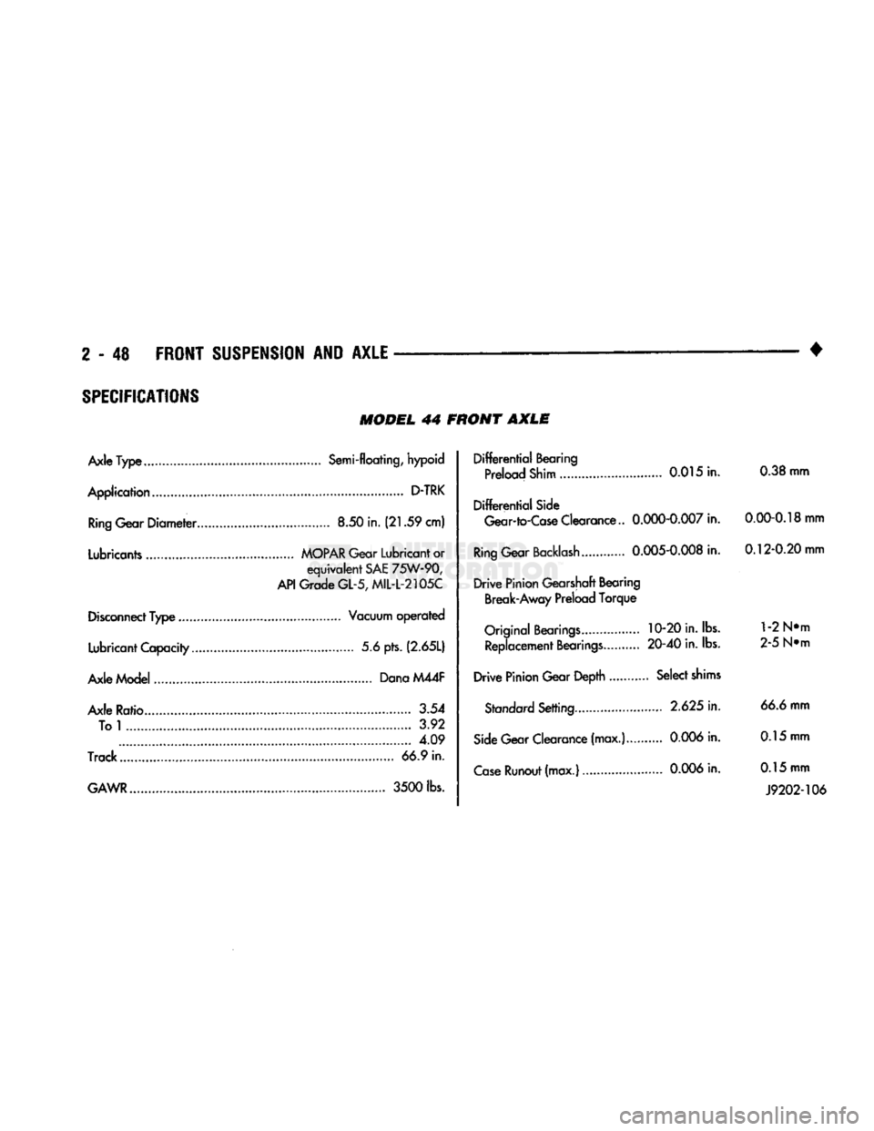
SPECIFICATIONS
MODEL
44 FRONT
AXLE
Axle
Type
Semi-floating, hypoid
Application
D-TRK
Ring
Gear
Diameter
8.50 in.
(21.59
cm)
Lubricants
MOPAR
Gear Lubricant or
equivalent
SAE
75W-90,
API
Grade
GL-5,
MIL-L-2105C
Disconnect
Type
Vacuum
operated
Lubricant Capacity 5.6 pts.
(2.65L)
Axle Model Dana M44F
Axle Ratio.. 3.54 To
1
3.92 4.09
Track
66.9 in.
GAWR
3500
lbs.
Differential
Bearing
Preload Shim 0.015 in. 0.38 mm
Differential
Side
Gear-to-Case
Clearance..
0.000-0.007
in.
0.00-0.18
mm
Ring
Gear
Backlash
0.005-0.008
in.
0.12-0.20
mm
Drive
Pinion Gearshaft Bearing Break-Away Preload
Torque
Original
Bearings
10-20 in. lbs.
1
-2 N»m Replacement
Bearings
20-40
in. lbs. 2-5 N»m
Drive
Pinion Gear Depth Select
shims
Standard
Setting
2.625
in. 66.6 mm
Side
Gear Clearance (max.)...
0.006
in. 0.15 mm
Case
Runout
(max.)
0.006
in. 0.15 mm
J9202-106
Page 128 of 1502
FRONT
SUSPENSION
AND
AXLE
2 - 75
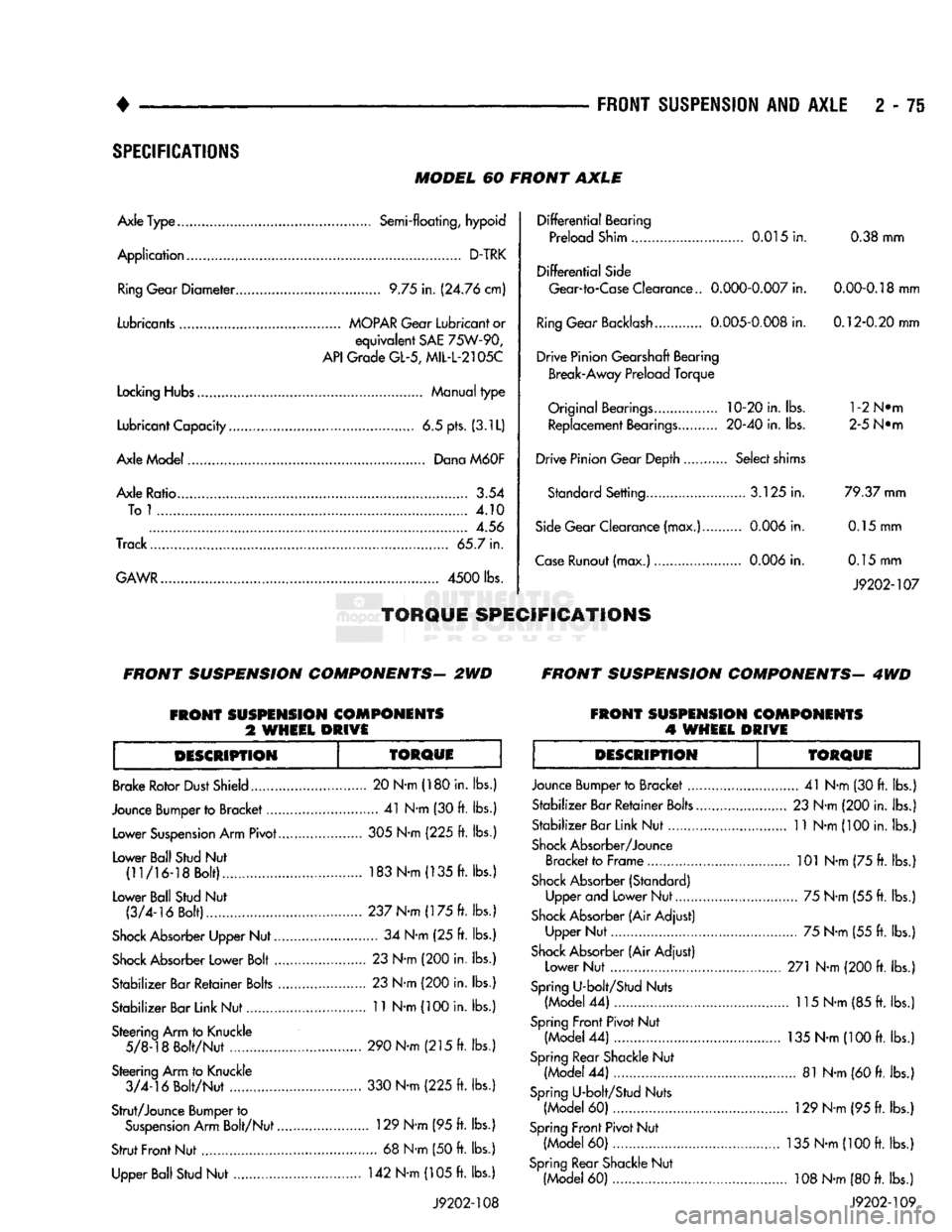
SPECIFICATIONS
MODEL
60
FRONT
AXLE
Axle Type........
Semi-floating,
hypoid
Application
D-TRK Ring Gear
Diameter
9.75
in.
(24.76 cm)
Lubricants
MOPAR
Gear
Lubricant
or
equivalent
SAE
75W-90,
API
Grade
GL-5,
MIL-L-2105C
Locking
Hubs Manual
type
Lubricant Capacity
6.5
pts. (3.1L)
Axle Model Dana
M60F
Axle Ratio.........
3.54
Tol
4.10
4.56
Track... 65.7
in.
GAWR....................
4500
lbs.
TORQUE
SPECIFICATIONS
Differential
Bearing
Preload Shim 0.015
in.
0.38
mm
Differential
Side Gear-to-Case Clearance..
0.000-0.007
in.
0.00-0.18
mm
Ring
Gear Backlash 0.005-0,008
in.
0.12-0.20 mm
Drive Pinion Gearshaft Bearing Break-Away Preload Torque
Original
Bearings....
10-20
in. lbs. l-2N®m Replacement Bearings. 20-40
in.
lbs. 2-5 N®m
Drive Pinion Gear Depth Select shims Standard Setting.... 3.125
in.
79.37 mm
Side
Gear Clearance (max.) 0.006
in.
0.15
mm
Case
Runout (max.) 0.006
in.
0.15
mm
J9202-107
FRONT
SUSPENSION
COMPONENTS-
2WD
FRONT
SUSPENSION
COMPONENTS-
4WD
FRONT
SUSPENSION
COMPONENTS
%
WHEEL
DRIVE
FRONT
SUSPENSION
COMPONENTS
4
WHEEL
DRIVE
DESCRIPTION
TOROUE
Brake Rotor
Dust
Shield
Jounce Bumper to Bracket.... Lower
Suspension
Arm Pivot.
Lower Ball Stud
Nut
(11/16-18 Bolt)...............
Lower Ball Stud
Nut
(3/4-16 Bolt).....
Shock
Absorber Upper Nut..
Shock
Absorber Lower Bolt
..
Stabilizer Bar Retainer
Bolts
.
Stabilizer Bar Link Nut
Steering Arm to Knuckle 5/8-18 Bolt/Nut
.............
Steering Arm to Knuckle 3/4-16 Bolt/Nut . 20 N-m (180 in.
lbs.
....
41
N-m
(30
ft. lbs.
305
N-m (225
ft. lbs.
183
N-m (135
ft. lbs.
237 N-m (175
ft. lbs.
....
34
N-m
(25 ft.
lbs. .
23
N-m
(200
in. lbs.
.
23
N-m
(200
in. lbs.
. 11 N-m
(100
in. lbs.
Strut/Jounce Bumper to
Suspension
Arm Bolt/Nut.
Strut
Front
Nut Upper Ball Stud
Nut
290 N-m (215
ft. lbs.
330 N-m (225
ft.
lbs.
.. 129 N-m (95
ft.
lbs.
....
68
N-m
(50
ft.
lbs.
142
N-m
(105
ft.
lbs.
J9202-108
DESCRIPTION
TORQUE
Jounce Bumper to Bracket
....
Stabilizer Bar Retainer
Bolts..
Stabilizer Bar Link Nut
Shock
Absorber/Jounce Bracket to Frame
Shock
Absorber (Standard) Upper and Lower Nut
Shock
Absorber (Air Adjust) Upper Nut
Shock
Absorber (Air Adjust) Lower Nut
Spring
U-bolt/Stud Nuts (Model
44) ...
Spring
Front Pivot Nut (Model
44)
Spring
Rear Shackle
Nut
(Model
44)
Spring
U-bolt/Stud Nuts (Model
60)
Spring
Front
Pivot Nut (Model
60)
Spring
Rear Shackle Nut (Model
60)
...
41
N-m (30
ft.
lbs.)
23
N-m (200 in.
lbs.)
11
N-m
(100
in.
lbs.)
.. 101 N-m (75
ft.
lbs.)
.... 75 N-m (55
ft.
lbs.)
.... 75 N-m (55
ft.
lbs.)
271 N-m
(200
ft.
lbs.)
.. 115 N-m (85
ft.
lbs.)
135
N-m (100
ft.
lbs.)
.... 81 N-m
(60
ft.
lbs.)
..
129
N-m
(95
ft.
lbs.)
135
N-m (100
ft.
lbs.)
,.
108
N-m
(80
ft.
lbs.)
J9202-109
Page 138 of 1502
REAR
SUSPENSION
AND
AXLE
3 - 9
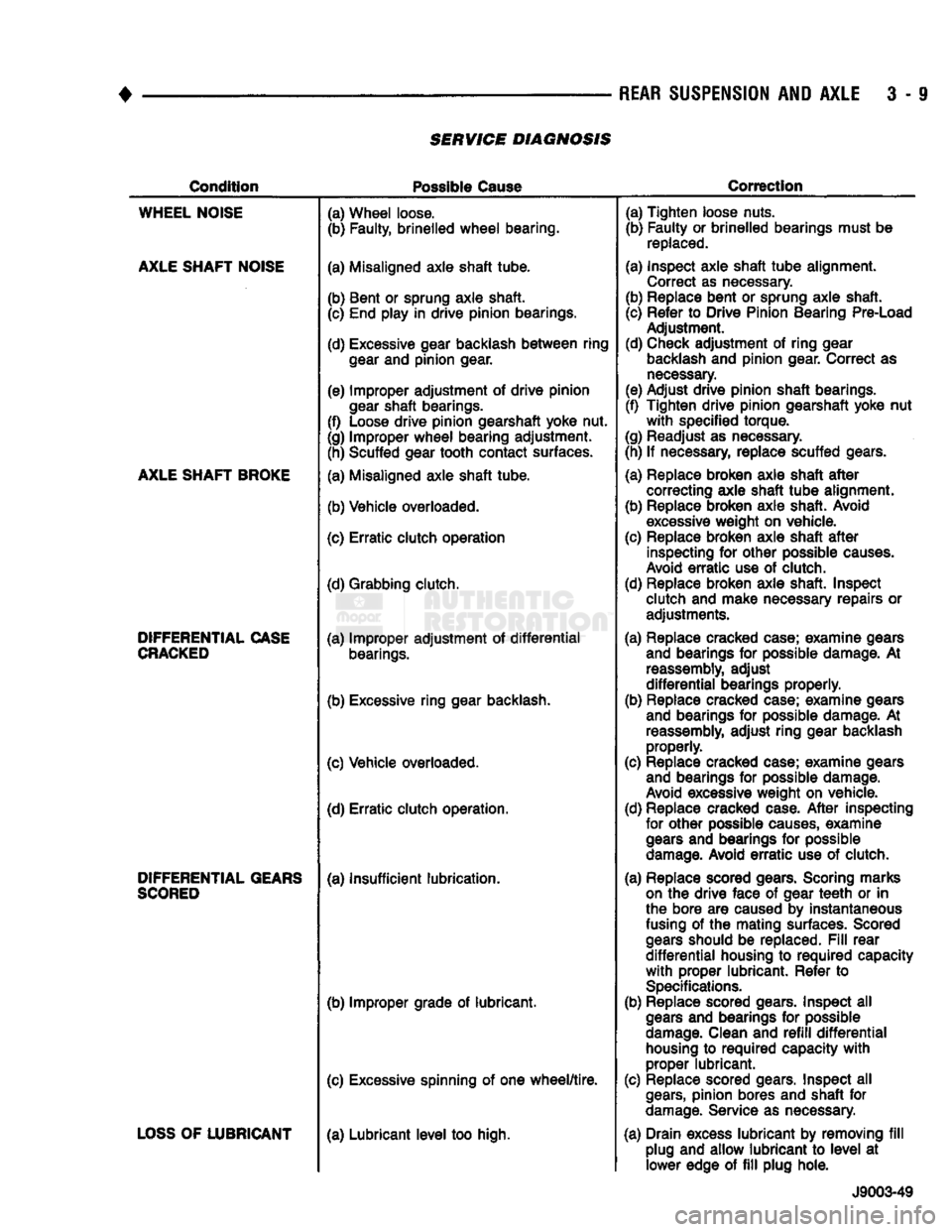
SERVICE DIAGNOSIS
Condition
Possible
Cause
Correction
WHEEL
NOISE
AXLE
SHAFT
NOISE
AXLE
SHAFT
BROKE
DIFFERENTIAL
CASE
CRACKED
DIFFERENTIAL
GEARS
SCORED
LOSS
OF
LUBRICANT
(a) Wheel loose.
(b) Faulty, brinelled
wheel
bearing.
(a) Misaligned axle shaft tube.
(b) Bent or sprung axle shaft. (c) End play in drive pinion bearings.
(d) Excessive gear backlash
between
ring
gear
and pinion gear.
(e) Improper adjustment of drive pinion
gear
shaft bearings.
(f) Loose drive pinion gearshaft yoke nut.
(g) Improper
wheel
bearing adjustment. (h) Scuffed gear tooth contact surfaces.
(a) Misaligned axle shaft tube.
(b) Vehicle overloaded.
(c) Erratic clutch operation
(d) Grabbing clutch.
(a) Improper adjustment of
differential
bearings.
(b) Excessive ring gear backlash.
(c) Vehicle overloaded. (d) Erratic clutch operation.
(a) Insufficient lubrication.
(b) Improper grade of lubricant.
(c) Excessive spinning of one
wheel/tire.
(a) Lubricant
level
too high. (a) Tighten loose nuts.
(b) Faulty or brinelled bearings must be
replaced.
(a) Inspect axle shaft
tube
alignment. Correct as necessary.
(b) Replace bent or sprung axle shaft.
(c) Refer to Drive Pinion Bearing Pre-Load Adjustment.
(d) Check adjustment of ring gear
backlash
and pinion gear. Correct as
necessary.
(e) Adjust drive pinion shaft bearings.
(f) Tighten drive pinion gearshaft yoke nut
with
specified torque.
(g) Readjust as necessary.
(h) If necessary, replace scuffed gears.
(a) Replace broken axle shaft
after
correcting axle shaft
tube
alignment.
(b) Replace broken axle shaft. Avoid
excessive
weight on vehicle.
(c) Replace broken axle shaft
after
inspecting for other possible
causes.
Avoid
erratic
use of clutch.
(d) Replace broken axle shaft. Inspect clutch and make necessary repairs or adjustments.
(a) Replace cracked case; examine gears and bearings for possible damage. At
reassembly,
adjust
differential
bearings properly.
(b) Replace cracked case; examine gears and bearings for possible damage. At
reassembly,
adjust ring gear backlash properly.
(c) Replace cracked case; examine gears and bearings for possible damage.
Avoid
excessive weight on vehicle.
(d) Replace cracked case.
After
inspecting for other possible
causes,
examine
gears
and bearings for possible
damage.
Avoid
erratic
use of clutch.
(a) Replace scored gears. Scoring marks
on
the drive face of gear
teeth
or in
the bore are caused by instantaneous
fusing
of the mating surfaces. Scored
gears
should be replaced.
Fill
rear
differential
housing to
required
capacity
with
proper lubricant. Refer to
Specifications.
(b) Replace scored gears. Inspect all
gears
and bearings for possible
damage.
Clean and
refill
differential
housing
to
required
capacity
with
proper lubricant.
(c) Replace scored gears. Inspect all
gears,
pinion bores and shaft for
damage.
Service as necessary.
(a) Drain excess lubricant by removing
fill
plug and allow lubricant to
level
at lower edge of
fill
plug hole.
J9003-49
Page 154 of 1502
•
REAR
SUSPENSION
AND
AXLE
3 - 27
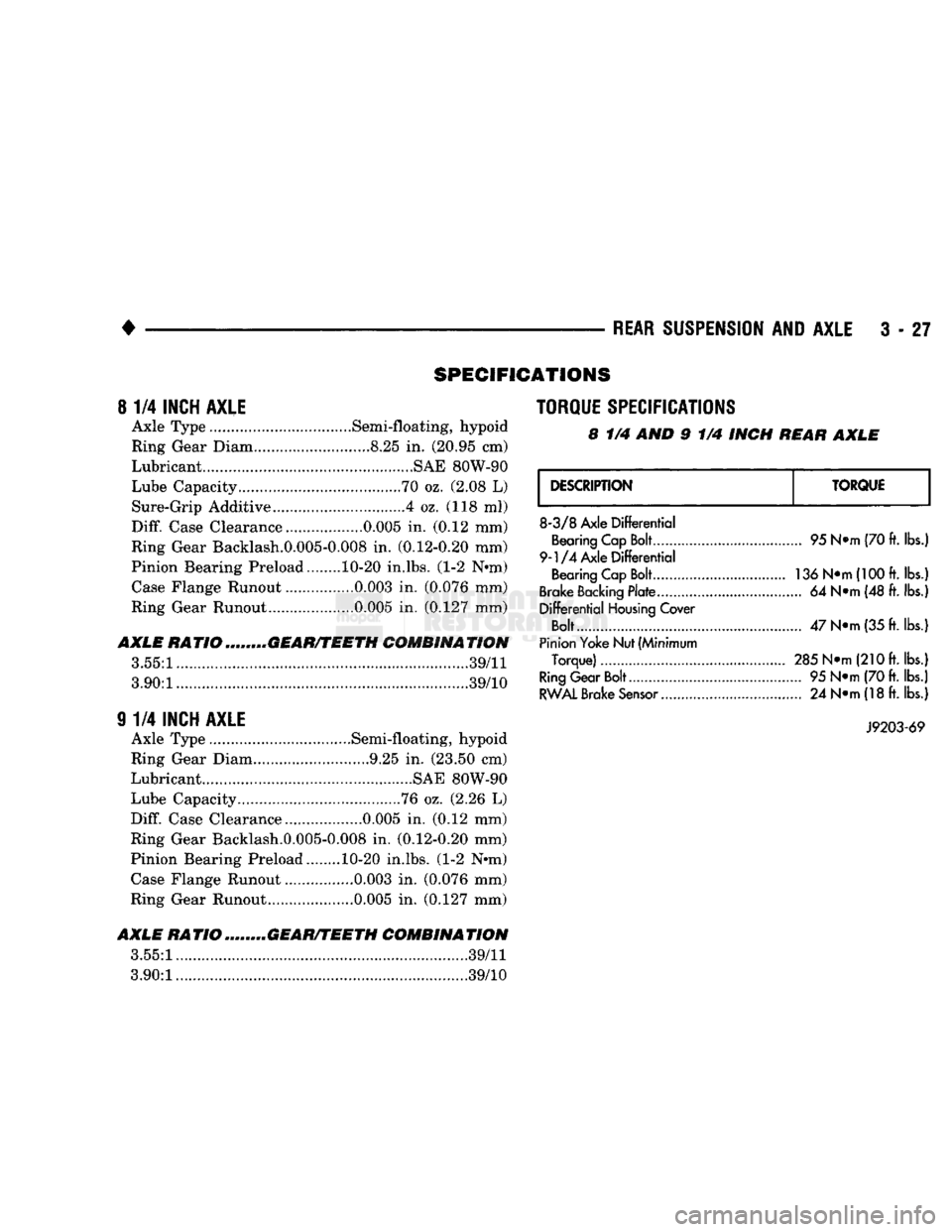
SPECIFICATIONS
8
1/4
INCH AXLE
Axle Type .Semi-floating, hypoid
Ring Gear Diam.. ....8.25
in.
(20.95 cm)
Lubricant............................. .........SAE 80W-90
Lube Capacity.....
70
oz. (2.08
L)
Sure-Grip Additive ....4 oz. (118
ml)
Diff.
Case Clearance.. 0.005
in.
(0.12 mm)
Ring Gear Backlash.0.005-0.008
in.
(0.12-0.20 mm)
Pinion Bearing Preload........ 10-20 in.lbs. (1-2 N*m) Case Flange Runout ................0.003
in.
(0.076 mm)
Ring Gear Runout ....0.005
in.
(0.127 mm)
AXLE
RATIOm„...,„GEAR/TEETH COMBINATION
3.55:1.....
39/11
3.90:1............
...............39/10
9
1/4
INCH AXLE
Axle Type .............Semi-floating, hypoid
Ring Gear Diam 9.25
in.
(23.50 cm)
Lubricant ....................SAE 80W-90
Lube Capacity ........76 oz. (2.26
L)
Diff.
Case Clearance 0.005
in.
(0.12 mm)
Ring Gear Backlash.0.005-0.008
in,
(0.12-0.20 mm)
Pinion Bearing Preload. 10-20 in.lbs. (1-2 Nnn) Case Flange Runout ................0.003
in.
(0.076 mm)
Ring Gear Runout..... .......0.005
in.
(0.127 mm)
AXLE
RATIO ........GEAR/TEETH COMBINATION
3.55:1.
.......39/11
3.90:1..............
39/10
TORQUE SPECIFICATIONS
8
1/4 AND 9 1/4
INCH
REAR AXLE
DESCRIPTION
TORQUE
8-3/8
Axle
Differential
Bearing Cap Bolt
9-1/4
Axle
Differential
Bearing Cap Bolt
Brake Backing
Plate
Differential
Housing
Cover
Bolt....
Pinion Yoke Nut (Minimum
Torque)
Ring
Gear Bolt
RWAL
Brake
Sensor...........
95 N*m (70 ft.
lbs.)
136 N»m(100ft.
lbs.!
... 64
N*m (48 ft. lbs.]
47
N»m
(35 ft.
lbs.)
285 N*m
(21
Oft. lbs.)
... 95
N*m (70 ft. lbs.)
... 24
N*m (18 ft.
lbs.)
J9203-69
Page 177 of 1502
3
- 50
REAR
SUSPENSION
AND
AXLE
• (6)
Install
the
RWAL brake
speed
sensor
and
cover
onto
the
axle
housing.
Tighten
the
sensor
to 24 Nsm (18 ft. lbs.)
torque.
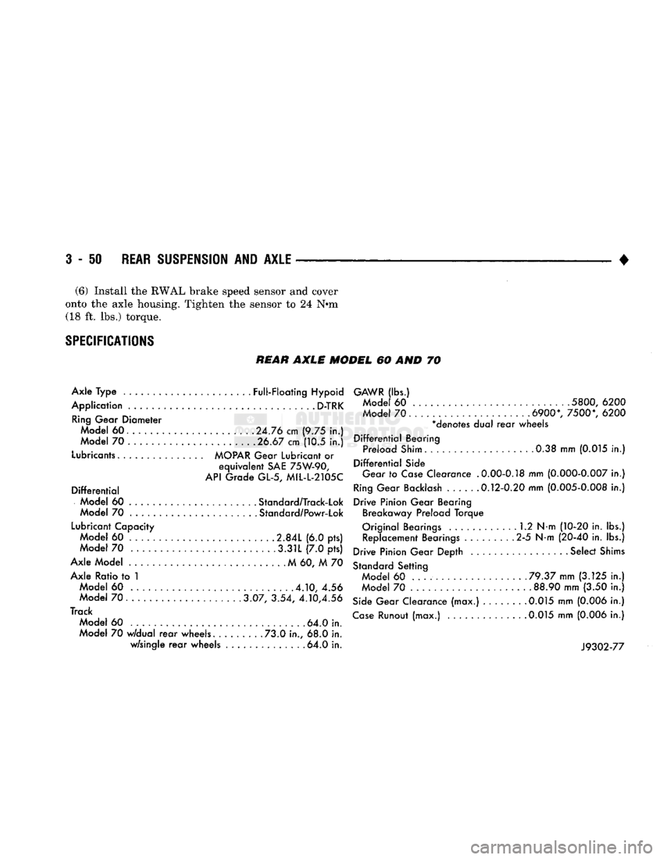
SPECIFICATIONS
REAR
AXLE MODEL 60 AND 70
Axle Type ......................
Full-Floating
Hypoid
Application
D-TRK
Ring
Gear Diameter Model 60. ............ .
.24.76
cm (9.75 in.)
Model 70 .................... .
.26.67
cm (10.5 in.)
Lubricants
MOPAR
Gear
Lubricant
or
equivalent
SAE
75W-90,
API
Grade GL-5, MIL-L-2105C
Differential
Model 60 .... . Standard/Track-Lok
Model 70 Standard/Powr-Lok
Lubricant
Capacity Model 60 .....
2.84L
(6.0 pts) Model 70 .3.31L (7.0 pts)
Axle Model M 60, M 70 Axle Ratio to 1 Model 60
.4.10,
4.56
Model
70......
3.07, 3.54,
4.10,4.56
Track Model 60 . 64.0 in.
Model 70
w/dual
rear
wheels. ....... .73.0 in., 68.0 in. w/single
rear
wheels ............. .64.0 in.
GAWR
(lbs.)
Mode
60
5800,
6200
Mode
70.
6900*,
7500*,
6200
*denotes dual
rear
wheels
Differential
Bearing Preload
Shim.
0.38 mm
(0.015
in.)
Differential
Side
Gear
to
Case
Clearance
.0.00-0.18
mm
(0.000-0.007
in.)
Ring
Gear
Backlash
.....
.0.12-0.20
mm
(0.005-0.008
in.)
Drive Pinion Gear Bearing Breakaway Preload Torque
Original Bearings 1.2 N-m
(10-20
in. lbs.) Replacement Bearings 2-5 N-m
(20-40
in. lbs.)
Drive Pinion Gear Depth ................. Select
Shims
Standard
Setting Model 60 ...
.79.37
mm
(3.125
in.)
Model 70 .
88.90
mm (3.50 in.)
Side
Gear Clearance (max.) 0.015 mm
(0.006
in.)
Case
Runout (max.)
.0.015
mm
(0.006
in.)
J9302-77
Page 302 of 1502
•
COOLING
SYSTEM
7 - 31 It utilizes thermal expansion and contraction of cool
ant to keep coolant free of trapped air. It provides a
volume for expansion and contraction of coolant. It
also provides a convenient and safe method for
checking coolant level and adjusting level at atmo
spheric pressure. This is done without removing ra
diator pressure cap. It also provides some reserve
coolant to cover minor leaks and evaporation or boil
ing losses.
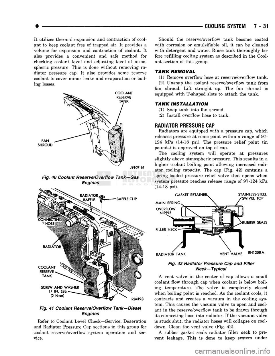
FAN
SHROUD
J9107-67
Fig.
40 Coolant Reserve/Overflow Tank—Gas
Engines
Fig.
41 Coolant Reserve/Overflow Tank—Diesel
Engines
Refer to Coolant Level Check—Service, Deaeration
and Radiator Pressure Cap sections in this group for
coolant reserve/overflow system operation and ser
vice.
Should the reserve/overflow tank become coated
with corrosion or emulsifiable oil, it can be cleaned
with detergent and water. Rinse tank thoroughly be
fore refilling cooling system as described in the Cool ant section of this group.
TANK REMOVAL
(1) Remove overflow hose at reserve/overflow tank.
(2) Unsnap the coolant reserve/overflow tank from
fan shroud. Lift straight up. The fan shroud is
equipped with T-shaped slots to attach the tank.
TANK INSTALLATION
(1) Snap tank into fan shroud.
(2) Install overflow hose to tank.
RADIATOR
PRESSURE
CAP
Radiators are equipped with a pressure cap, which
releases pressure at some point within a range of 97- 124 kPa (14-18 psi). The pressure relief point (in
pounds) is engraved on top of cap. The cooling system will operate at pressures
slightly above atmospheric pressure. This results in a
higher coolant boiling point allowing increased radi ator cooling capacity. The cap (Fig. 42) contains a
spring-loaded pressure relief valve that opens when
system pressure reaches release range of 97-124 kPa (14-18 psi).
Fig.
42 Radiator
Pressure
Cap and
Filler
Neck—Typical
A vent valve in the center of cap allows a small
coolant flow through cap when coolant is below boil
ing temperature. The valve is completely closed
when boiling point is reached. As the coolant cools, it contracts and creates a vacuum in the cooling sys
tem. This causes the vacuum valve to open and cool ant in the reserve/overflow tank to be drawn through
its connecting hose into radiator. If the vacuum valve
is stuck shut, the radiator hoses will collapse on cool-
down. Clean the vent valve (Fig. 42).
A rubber gasket seals radiator filler neck to pre
vent leakage. This is done to keep system under
Page 311 of 1502
ENGINE ACCESSORY DRIVE BELTS
INDEX
page
Automatic Belt Tensioner
45
Belt Diagnosis
40
Belt Removal/Installation
. 40
page
Belt Schematics
40
Belt Tension
40
General
Information
40
GENERAL
INFORMATION
All vehicles are available with either
a
3.9L (V-6),
a 5.2L (V-8),
a
5.9L (gas V-8) or
a
5.9L (in-line 6 cyl
inder diesel) engine. The accessory drive components
are
operated
by a
single, crankshaft driven, serpentine drive belt on all
engines. An automatic belt tensioner
is
used to main
tain correct belt tension
at all
times. Refer
to
Auto matic Belt Tensioner proceeding
in
this group.
BELT DIAGNOSIS SERPENTINE DRIVE BELT DIAGNOSIS-ALL
ENGINES
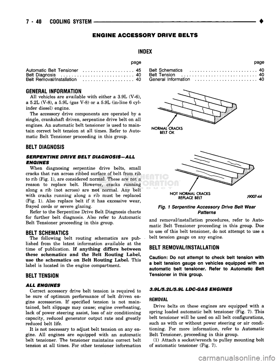
When diagnosing serpentine drive belts, small
cracks that run across ribbed surface of belt from rib
to rib (Fig. 1), are considered normal. These are not
a
reason
to
replace belt. However, cracks running along
a rib (not
across)
are not
normal.
Any
belt
with cracks running along
a rib
must
be
replaced (Fig.
1).
Also replace belt
if it has
excessive wear,
frayed cords
or
severe glazing.
Refer to the Serpentine Drive Belt Diagnosis charts
for further belt diagnosis. Also refer
to
Automatic Belt Tensioner proceeding
in
this group.
BELT SCHEMATICS
The following belt routing schematics
are
pub
lished from
the
latest information available
at the
time
of
publication.
If
anything differs between
these schematics
and the
Belt Routing Label,
use
the
schematics
on
Belt Routing Label. This
label
is
located
in
the engine compartment.
BELT TENSION
ALL
ENGINES
Correct accessory drive belt tension
is
required
to
be sure
of
optimum performance
of
belt driven
en
gine accessories.
If
specified tension
is not
main
tained, belt slippage may cause; engine overheating, lack
of
power steering assist, loss
of
air conditioning
capacity, reduced generator output rate and greatly
reduced belt life.
It
is
not necessary
to
adjust belt tension on any en
gine.
All
engines
are
equipped with
an
automatic
belt tensioner. The tensioner maintains correct belt tension
at all
times. For other tensioner information
NORMAL CRACKS
BELT
OK
NOT NORMAL CRACKS
REPLACE
BELT
J9007-44
Fig. 1 Serpentine Accessory Drive Belt Wear Patterns
and removal/installation procedures, refer
to
Auto
matic Belt Tensioner proceeding
in
this group.
Due
to use
of
this belt tensioner, do not attempt
to
use
a
belt tension gauge
on
any engine.
BELT REMOVAL/INSTALLATION
Caution:
Do not
attempt
to
check belt tension with
a
belt
tension gauge
on
vehicles equipped with
an
automatic belt tensioner. Refer
to
Automatic Belt
Tensioner
in
this
group.
3.9L/5,2U5*9L
LDC-GAS ENGINES
REMOVAL
Drive belts
on
these engines
are
equipped with
a
spring loaded automatic belt tensioner (Fig.
7).
This
belt tensioner will
be
used on
all
belt configurations, such
as
with
or
without power steering
or
air condi
tioning.
For
more information, refer
to
Automatic Belt Tensioner, proceeding
in
this group.
(1) Attach
a
socket/wrench
to
pulley mounting bolt
of automatic tensioner (Fig.
7).
Page 320 of 1502
SPECIFICATIONS
GENERAL
INFORMATION
The following specifications are published from the
latest information available at the time of publica
tion. If anything differs between the specifica
tions found on the Vehicle Emission Control
Information (VECI) label and the following spec
ifications, use specifications on VECI label. The
VECI label is located in the engine compartment.
DRIVE
BELT
TENSION
All engines are equipped with a spring loaded au
tomatic belt tensioner. Do not attempt to check belt
tension with a belt tension gauge on vehicles
equipped with an automatic belt tensioner. Refer to
Automatic Belt Tensioner in this group.
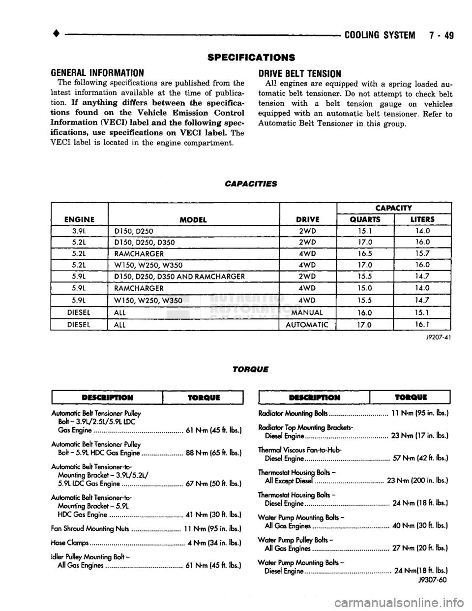
CAPACITIES
ENGINE
MODEL
DRIVE
CAPACITY
ENGINE
MODEL
DRIVE
QUARTS
LITERS
3.9L D150,
D250
2WD
15.1 14.0
5.2L D150, D250,
D350
2WD
17.0 16.0
5.2L
RAMCHARGER
4WD
16.5 15.7
5.2L W150, W250,
W350
4WD
17.0 16.0
5.9L D150, D250,
D350
AND
RAMCHARGER
2WD
15.5 14.7
5.9L
RAMCHARGER
4WD
15.0 14.0
5.9L W150, W250,
W350
4WD
15.5 14.7
DIESEL
ALL
MANUAL
16.0 15.1
DIESEL
ALL
AUTOMATIC
17.0 16.1
J9207-41
TORQUE
DISCMPflON
TORQUE
TORQUi
Automatic Belt Tensioner Pulley
Bolt-3.9l/2.5L/5.9LLDC
Gas
Engine
61
N-m (45
ft.
lbs.)
Automatic Belt Tensioner Pulley
Bolt
-
5.9L
HDC
Gas
Engine
88
N-m
(65
ft.
lbs.)
Automatic Belt Tensioner-to- Mounting Bracket
-
3.9L/5.2L/ 5.9L IDC
Gas
Engine
67
N-m
(50
ft.
lbs.)
Automatic Belt Tensioner-to- Mounting Bracket
-
5.9L
HDC
Gas
Engine
41
N-m
(30
ft.
lbs.)
Fan
Shroud
Mounting Nuts
11
N-m
(95
in. lbs.)
Hose
Clamps
4
N-m
(34
in. lbs.)
Idler
Pulley Mounting
Bolt
-
All
Gas
Engines
61
N-m
(45
ft.
lbs.)
Radiator Mounting
Bobs
11
N-m
(95
in. lbs.)
Radiator
Top
Mounting Brackets- Diesel Engine...... 23 N-m
(17
in. lbs.)
Thermal
Viscous
Fan-to-Hub- Diesel Engine
57
N-m
(42
ft.
lbs.)
Thermostat
Housing
Bolts
-
All Except Diesel 23 N-m (200 in. lbs.)
Thermostat
Housing
Bolts
-
Diesel Engine
24
N-m
(18
ft.
lbs.)
Water
Pump
Mounting
Bolts
-
All
Gas
Engines
40
N-m
(30
ft.
lbs.)
Water
Pump
Pulley
Bolts
-
All
Gas
Engines
27 N-m (20
ft.
lbs.)
Water
Pump
Mounting
Bolts
-
Diesel Engine
24
N-m(18ft.
lbs.) J9307-60