1993 DODGE TRUCK load capacity
[x] Cancel search: load capacityPage 1047 of 1502
21
- 46
G360
MANUAL
TRANSMISSION
G360
MANUAL
TRANSMISSION
INDEX
page
Gear Ratios
46
General
Information
46
Recommended
Lubricant
46
Transmission
Identification
46
Transmission
Installation—2-Wheel
Drive
. 50
GENERAL
INFORMATION
The Getrag G360 transmission
is
used exclusively
with
the
Cummins turbo diesel engine.
It is a
heavy duty, 5-speed, fully synchronized manual transmission
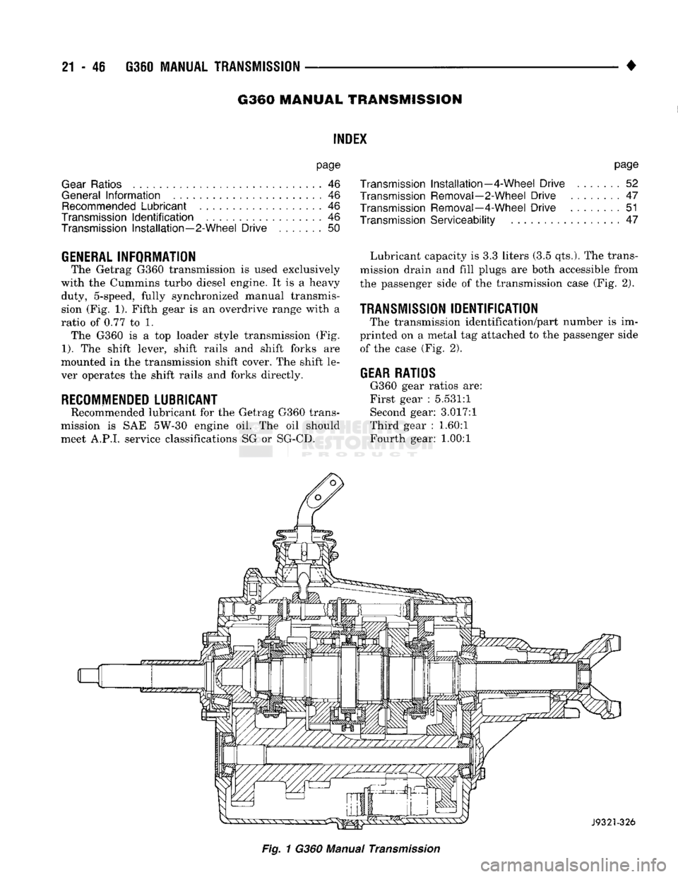
(Fig.
1).
Fifth gear
is an
overdrive range with
a
ratio
of
0.77
to 1.
The G360
is a top
loader style transmission
(Fig.
1).
The
shift lever, shift rails
and
shift forks
are
mounted
in the
transmission shift cover.
The
shift
le
ver operates
the
shift rails
and
forks directly.
RECOMMENDED
LUBRICANT
Recommended lubricant
for the
Getrag G360 trans
mission
is SAE
5W-30 engine
oil. The oil
should meet A.P.I, service classifications
SG or
SG-CD.
page
Transmission
Installation—4-Wheel
Drive
.......
52
Transmission Removal—2-Wheel
Drive
........
47
Transmission Removal—4-Wheel
Drive
51
Transmission
Serviceability
47
Lubricant capacity
is 3.3
liters
(3.5
qts.).
The
trans
mission drain
and
fill plugs
are
both accessible from
the passenger side
of
the
transmission case
(Fig.
2).
TRANSMISSION
IDENTIFICATION
The transmission identification/part number
is im
printed
on a
metal
tag
attached
to the
passenger side of
the
case
(Fig.
2).
GEAR
RATIOS
G360 gear ratios
are:
First gear
:
5.531:1 Second gear: 3.017:1
Third gear
:
1.60:1
Fourth gear:
1.00:1
Fig.
1
G360 Manual
Transmission
Page 1084 of 1502
•
AUTOMATIC TRANSiISSIO|-32RH/8iRH/37RH/42RH/4iRH
21 - 83 plate. The overdrive clutch also disengages the direct
clutch during 3-4 upshifts. As fluid pressure extends
the overdrive piston, the piston contacts the direct clutch hub pressing it rearward. This action com
presses the direct clutch spring relieving spring load on the clutch pack. The clutch is disengaged once
spring load is relieved.
The 3-4 accumulator cushions overdrive clutch en
gagement to smooth the transition into fourth gear.
The accumulator is charged at the same time as ap
ply pressure acts against the overdrive piston.
Converter clutch engagement in overdrive fourth
gear is controlled by sensor inputs to the powertrain
control module. In third gear above 25 mph, sensor inputs to the control module that determine clutch
engagement and shift timing are:
• coolant temperature (verifies minimum of 60° F)
• engine speed • vehicle speed
• throttle position
• manifold vacuum (MAP sensor)
Gearshift
Mechanism
The gear shift mechanism provides the same shift
positions used with 3-speed Chrysler transmissions
(P-R-N-D-2-1).
The shift into overdrive fourth gear range occurs
only after the transmission has completed the shift into D third gear range. No further movement of the
shift mechanism is required to complete the 3-4 shift.
The fourth gear upshift occurs automatically when
the overdrive control switch is in the ON position. Shift timing is determined by sensor inputs to the
engine controller.
Overdrive Control
Switch
The overdrive control switch is located in the in
strument panel. In the On position, automatic shifts
into fourth gear overdrive will occur. In the Off posi
tion, the switch overrides the engine controller pre
venting a shift to overdrive fourth gear range.
The switch has an indicator light that illuminates
when overdrive is turned off. The switch also resets
when the ignition key is turned to the OFF position so that the automatic overdrive feature is restored.
The use of fault codes is employed to help diagnose
the electronic components that operate the overdrive
unit and converter clutch.
HYDRAULIC
CONTROLS
The 42REJ/46RH hydraulic control system provides
fully automatic operation. The system performs five
basic functions which are: pressure supply, pressure regulation, flow control, clutch/band application, and
lubrication. 42RH/46RH system operation is similar to that de
scribed in the 32RH/36RH/37RH General Informa tion section. The main difference being fourth gear
operation which is covered here.
Pressure
Regulation
The pressure regulator valve maintains line pres
sure.
The amount of pressure developed is controlled
by throttle pressure which is dependent on the de gree of throttle opening. The regulator valve is lo
cated in the valve body.
The throttle valve determines line pressure and
shift speed. Governor pressure increases in propor
tion to vehicle speed. The throttle valve controls up shift and downshift speeds by regulating pressure
according to throttle position.
Flow
Control And Lubrication The manual valve is operated by the gearshift link
age and provides the operating range selected by the
driver.
The 1-2 shift valve provides 1-2 or 2-1 shifts and
the 2-3 shift valve provides 2-3 or 3-2 shifts.
The kickdown valve provides forced 3-2 or 3-1
downshifts depending on vehicle speed. Downshifts
occur when the throttle is opened beyond downshift
detent position which is just before wide open throt
tle.
The 2-3 valve throttle pressure plug provides 3-2
downshifts at varying throttle openings depending on
vehicle speed.
The 1-2 shift control valve transmits 1-2 shift pres
sure to the accumulator piston. This controls kick-
down band capacity on 1-2 upshifts and 3-2 downshifts.
The 3-4 shift valve, shuttle valve, timing valve and
accumulator are only actuated when the overdrive
solenoid is energized.
The solenoid contains a check ball that controls a
vent port to the 3-4 valve. The check ball either di
verts line pressure away from or directly to, the 3-4 shift valve. Energizing the solenoid causes the check
ball to close the vent port allowing line pressure to act upon the 3-4 upshift valve.
The limit valve determines maximum speed at
which a 3-2 part throttle kickdown can be made. Some transmissions do not have the limit valve and
maximum speed for a 3-2 kickdown is at the detent
position.
The 2-3 shuttle valve has two functions. First is
fast front band release and smooth engagement dur ing lift-foot 2-3 upshifts. The second is to regulate
front clutch and band application during 3-2 down
shifts.
The 3-4 shuttle valve uses a combination of throt
tle and governor pressure to control the rate of over
drive piston apply and release. This is done to
maintain shift quality at varying throttle openings.
Page 1104 of 1502
•
AUTOMATIC
TRANSMISSION—32RH/36RH/37RH/42RH/46RH
21-103
TRANSMISSION DIAGNOSIS
Condition
Possible
Couso
Correction
OVERHEAT
DURING
COMMERCIAL
OPERATION
OR
WHILE
TRAILER
TOWING
(FLUID
DARK
AND
BURNED
WITH
SOME
SLUDGE
FORMATION)
1.
Vehicle not properly equipped for
trailer
towing or
commercial use
2. Vehicle not equipped
with
auxiliary fluid cooler
3.
Extensive idling
time
or operation in heavy
traffic
in hot weather
4. Tow vehicle overloaded (exceeding vehicle tow capacity)
5. Air flow to auxiliary cooler blocked by snow plow,
front
mounted spare
tire,
bug screen, or similar
item
1.
Be sure vehicle is equipped
with
recommended
optional components
(i.e.,
HD
springs,
transmission,
axle, larger CID engine, auxiliary cooler, correct axle ratio, etc.). If vehicle is not so
equipped, it should not be used for severe
service operation
2. Drain fluid, change
filter,
and install auxiliary cooler
3.
Cut down on idling time; shift into
neutral
every
so
often and run engine at 1000 rpm to help
circulate fluid through cooler
4. Be sure vehicle is properly equipped to handle
load;
do not tow
Class
Ill-type loads
with
a
vehicle
that
is only
rated
for
Class
1
or II operation
5.
Remove or reposition
item
causing
air flow
blockage
OVERHEAT
DURING
NORMAL
OPERATION
(FLUID
DISCOLORED,
SMELLS
BURNED)
1.
Low
fluid
level
2. Fluid cooler, lines blocked, or cooler cracked (oil in engine coolant)
3.
Switch valve sticking
4. Clutch pack clearance incorrect (too tight)
5.
Bands
too tight 1. Add
fluid
and check for leaks
2. Flush cooler and lines and replace radiator if
transmission
fluid has
entered
coolant
3.
Remove,
disassemble,
clean valve body
4. Check and correct as required
5. Adjust bands
J9121-450
Page 1105 of 1502
21 - 104
AUTOMATIC
TRANSMISSION—32RH/36RH/37RH/42RH/46RH
•
Condition
POMIOSO
Ccwse
Correction
NO
START
IN
PARK
OR
NEUTRAL
1.
Gearshift
linkage
out
of
adjustment
2.
Neutral
switch
wire
broken
or
open
3.
Faulty
neutral
switch
4.
Valve
body
manual
lever
assembly
bent,
worn,
broken,
or not
aligned
with
switch
1.
Adjust linkage
2.
Check continuity
with
test lamp; repair as required
3.
Refer to service section for test and replacement procedure
4.
inspect lever
assembly
and replace if damaged
SLUGGISH
ACCELERATION
AT
LOW
SPEEDS
OR
REQUIRES
EXCESSIVE
THROTTLE
OPENING
TO MAINTAIN
HIGHWAY
SPEEDS
1.
Poor
engine
performance
2.
Gearshift
or
throttle
linkage
out of adjustment
3.
Transmission
clutches slipping
4.
Overrunning clutch in converter not holding
5. Converter overrunning clutch stuck
1.
Check engine and repair as required
2. Adjust linkage
3. Perform stall test and repair as required
4.
Perform stall test and replace converter if clutch
has
failed
5. Replace converter
FLUID
CONTAMINATED
(DISCOLORED,
FULL
OF
SLUDGE
AND/OR
METAL
AND
FRICTION
MATERIAL
PARTICULAR)
1.
If contamination occurred shortly
after
overhaul,
fluid cooler and
lines
were
not
flushed
and flow rested. This is especially
true
when original overhaul
was
to correct a problem
that
generated a large
amount of debris,
such
as a gear
failure
or a clutch
pack
failure
Note: Flushing the cooler and lines is mandatory
after
a
failure
of the converter lockup clutch
2.
Incorrect fluid used in transmission
3. Main cooler in radiator is cracked, allowing engine coolant to
enter
transmission
4.
Severe overload results in overheat, fluid break
down,
and accelerated wear, especially in high
ambient temperatures.
Most
frequent
causes
are:
• Vehicle is not properly equipped for heavy duty
service
• Tow vehicle and boat or
trailer
are both overloaded
•
Trailer
or boat are too large for tow vehicle (load exceeds rated capacity of tow vehicle)
1.
If contamination is severe, cooler flushing,
converter replacement, and another overhaul may be
necessary;
particularly so if shift
problems
were
also
present
2.
If
transmission
is operating properly, drain fluid, reverse flush cooler and lines, and change fluid
and
filter.
However, if shift problem has
developed, converter replacement and
transmission
overhaul may be required
3.
Replace radiator (and cooler) and flush lines. If problem was
diagnosed
early
enough,
fluid and
filter
change
may
only
be
necessary.
If
contamination perioa was prolonged, overhaul
and
converter replacement may be required
4.
Repair
transmission,
flush cooler, and lines.
Replace
converter if
necessary.
Install auxiliary
cooler if needed.
Also
install HD cooling system if needed. If tow vehicle and unit being towed
are both overloaded, the only repair is to reduce
the load to
rated
limits. However, if
trailer
or boat is too large for tow vehicle, the only option
is
for the owner to move up to properly-
equipped and load-rated tow vehicle
J9121-449
TRANSMISSION DIAGNOSIS
Page 1371 of 1502
22 - 2
WHEELS
AND
TIRES
•
METRIC
TIRE
SIZES
P
205 / 75 I 15
J9322-6
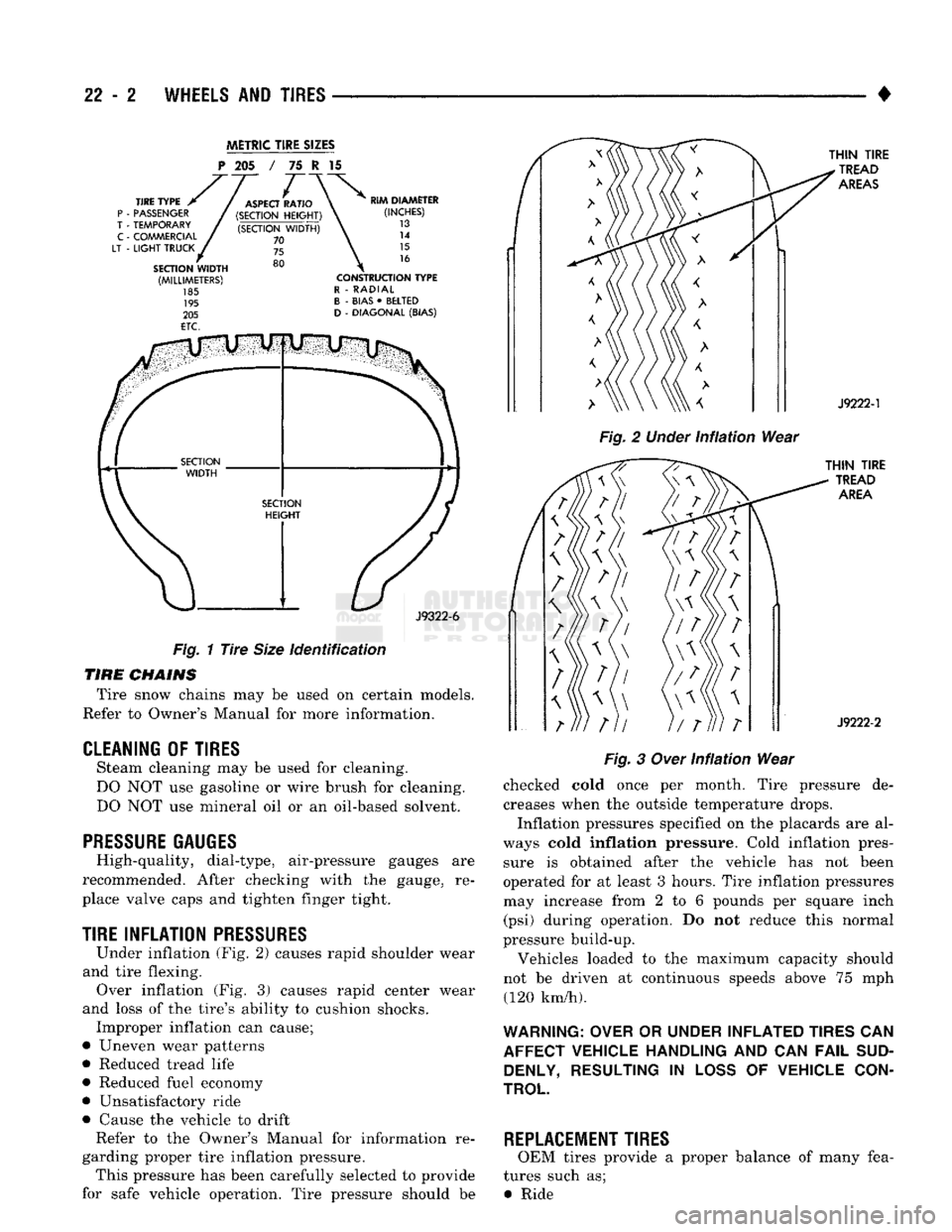
Fig.
1
Tire
Size
identification
TIRE
CHAINS
Tire snow chains may be used on certain models.
Refer to Owner's Manual for more information.
CLEANING
OF
TIRES
Steam cleaning may be used for cleaning.
DO NOT use gasoline or wire brush for cleaning.
DO NOT use mineral oil or an oil-based solvent.
PRESSURE GAUGES
High-quality, dial-type, air-pressure gauges are
recommended. After checking with the gauge, re
place valve caps and tighten finger tight.
TIRE
INFLATION
PRESSURES
Under inflation (Fig. 2) causes rapid shoulder wear
and tire flexing. Over inflation (Fig. 3) causes rapid center wear
and loss of the tire's ability to cushion shocks. Improper inflation can cause;
• Uneven wear patterns
• Reduced tread life
• Reduced fuel economy
• Unsatisfactory ride
• Cause the vehicle to drift Refer to the Owner's Manual for information re
garding proper tire inflation pressure. This pressure has been carefully selected to provide
for safe vehicle operation. Tire pressure should be
Fig.
2
Under
infiation
Wear
Fig.
3
Over
Infiation
Wear
checked cold once per month. Tire pressure de creases when the outside temperature drops.
Inflation pressures specified on the placards are al
ways cold
inflation
pressure. Cold inflation pres sure is obtained after the vehicle has not been
operated for at least 3 hours. Tire inflation pressures may increase from 2 to 6 pounds per square inch (psi) during operation. Do not reduce this normal
pressure build-up.
Vehicles loaded to the maximum capacity should
not be driven at continuous speeds above 75 mph (120 km/h).
WARNING: OVER
OR
UNDER INFLATED TIRES
CAN
AFFECT VEHICLE HANDLING
AND CAN
FAIL
SUD DENLY, RESULTING
IN
LOSS
OF
VEHICLE CON
TROL
REPLACEMENT TIRES
OEM tires provide a proper balance of many fea
tures such as; • Ride
Page 1375 of 1502
22 - e
WHEELS
AND
TIRES
• WHEELS
GENERAL
INFORMATION
Original equipment wheels are designed for all
loads up to the specified Maximum Vehicle Capacity. All models use steel or cast aluminum drop center
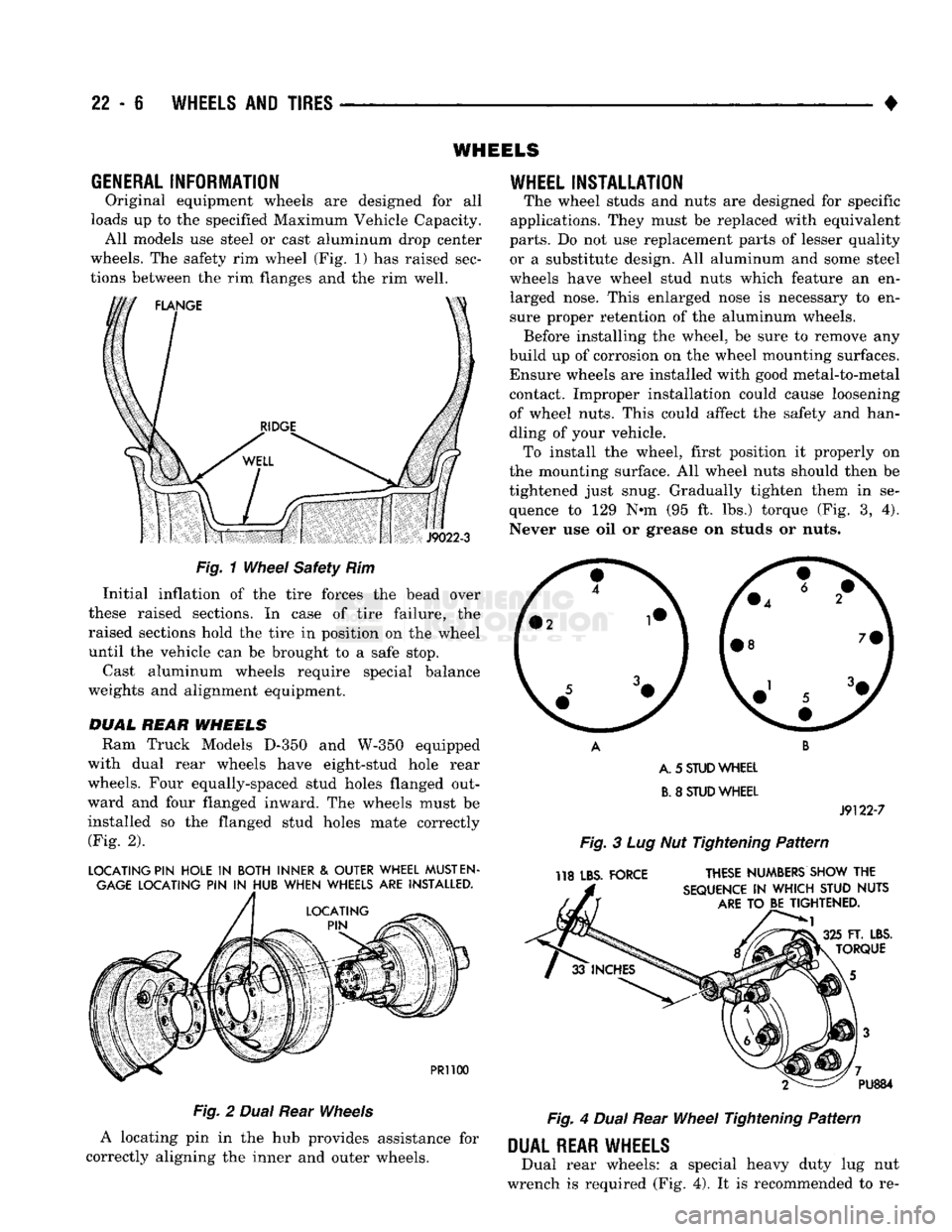
wheels. The safety rim wheel (Fig. 1) has raised sec
tions between the rim flanges and the rim well.
S
J9022-3
Fig.
1
Wheel
Safety Rim Initial inflation of the tire forces the bead over
these raised sections. In case of tire failure, the
raised sections hold the tire in position on the wheel
until the vehicle can be brought to a safe stop.
Cast aluminum wheels require special balance
weights and alignment equipment.
DUAL
REAR
WHEELS
Ram Truck Models
D-350
and
W-350
equipped
with dual rear wheels have eight-stud hole rear
wheels. Four equally-spaced stud holes flanged out
ward and four flanged inward. The wheels must be
installed so the flanged stud holes mate correctly (Fig. 2).
LOCATING PIN HOLE
IN
BOTH INNER
&
OUTER WHEEL
MUST
EN
GAGE
LOCATING PIN
IN
HUB WHEN WHEELS ARE INSTALLED.
PR1100
Fig.
2
Dual
Rear
Wheels
A locating pin in the hub provides assistance for
correctly aligning the inner and outer wheels.
WHEEL
INSTALLATION
The wheel studs and nuts are designed for specific
applications. They must be replaced with equivalent
parts.
Do not use replacement parts of lesser quality or a substitute design. All aluminum and some steel
wheels have wheel stud nuts which feature an en larged nose. This enlarged nose is necessary to en
sure proper retention of the aluminum wheels. Before installing the wheel, be sure to remove any
build up of corrosion on the wheel mounting surfaces. Ensure wheels are installed with good metal-to-metal contact. Improper installation could cause loosening
of wheel nuts. This could affect the safety and han
dling of your vehicle. To install the wheel, first position it properly on
the mounting surface. All wheel nuts should then be
tightened just snug. Gradually tighten them in se
quence to 129 N-m (95 ft. lbs.) torque (Fig. 3, 4).
Never use oil or grease on studs or nuts.
A. 5
STUD
WHEEL
B.
8
STUD
WHEEL
J9122-7
Fig.
3 Lug Nut Tightening
Pattern
118 LBS. FORCE THESE NUMBERS SHOW THE
SEQUENCE
IN
WHICH STUD NUTS
ARE
TO BE TIGHTENED.
FT. LBS.
TORQUE PU884
Fig.
4
Dual
Rear
Wheel
Tightening
Pattern
DUAL
REAR WHEELS
Dual rear wheels: a special heavy duty lug nut
wrench is required (Fig. 4). It is recommended to re-
Page 1376 of 1502
•
WHEELS
AND
TIRES
22 - 7 move and install dual rear wheels only when the
proper wrench is available.
INSTALLATION
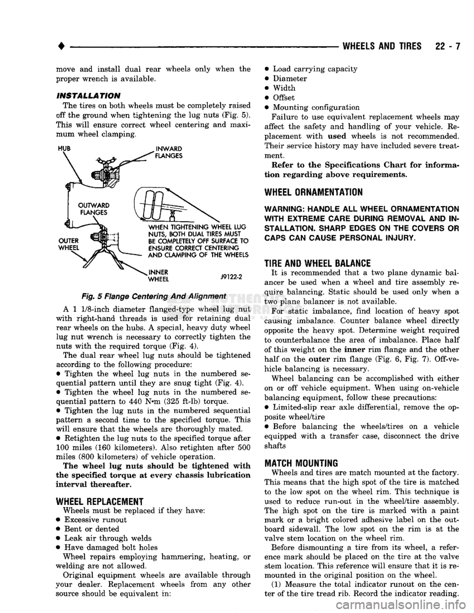
The tires on both wheels must be completely raised
off the ground when tightening the lug nuts (Fig. 5).
This will ensure correct wheel centering and maxi mum wheel clamping.
HUB
^
INWARD
Fig.
5 Flange Centering And
Alignment
A 1
1/8-inch
diameter flanged-type wheel lug nut
with right-hand threads is used for retaining dual rear wheels on the hubs. A special, heavy duty wheel lug nut wrench is necessary to correctly tighten the nuts with the required torque (Fig. 4).
The dual rear wheel lug nuts should be tightened
according to the following procedure:
• Tighten the wheel lug nuts in the numbered se
quential pattern until they are snug tight (Fig. 4).
• Tighten the wheel lug nuts in the numbered se
quential pattern to 440 N#m (325 ft-lb) torque.
• Tighten the lug nuts in the numbered sequential
pattern a second time to the specified torque. This will ensure that the wheels are thoroughly mated. • Retighten the lug nuts to the specified torque after 100 miles (160 kilometers). Also retighten after 500
miles (800 kilometers) of vehicle operation.
The wheel lug nuts should be tightened with
the specified torque at every chassis lubrication
interval thereafter.
WHEEL REPLACEMENT
Wheels must be replaced if they have:
• Excessive runout
• Bent or dented
• Leak air through welds
• Have damaged bolt holes Wheel repairs employing hammering, heating, or
welding are not allowed. Original equipment wheels are available through
your dealer. Replacement wheels from any other source should be equivalent in: • Load carrying capacity
• Diameter
® Width
• Offset
• Mounting configuration
Failure to use equivalent replacement wheels may
affect the safety and handling of your vehicle. Re
placement with used wheels is not recommended.
Their service history may have included severe treat ment.
Refer to the Specifications Chart for informa
tion regarding above requirements.
WHEEL ORNAMENTATION
WARNING; HANDLE
ALL
WHEEL ORNAMENTATION
WITH
EXTREME CARE DURING REMOVAL
AND IN
STALLATION. SHARP EDGES
ON THE
COVERS
OR
CAPS
CAN
CAUSE PERSONAL INJURY.
TIRE AND WHEEL BALANCE
It is recommended that a two plane dynamic bal
ancer be used when a wheel and tire assembly re
quire balancing. Static should be used only when a
two plane balancer is not available. For static imbalance, find location of heavy spot
causing imbalance. Counter balance wheel directly
opposite the heavy spot. Determine weight required
to counterbalance the area of imbalance. Place half of this weight on the inner rim flange and the other
half on the outer rim flange (Fig. 6, Fig. 7). Off-ve
hicle balancing is necessary. Wheel balancing can be accomplished with either
on or off vehicle equipment. When using on-vehicle
balancing equipment, follow these precautions: • Limited-slip rear axle differential, remove the op
posite wheel/tire • Before balancing the wheels/tires on a vehicle
equipped with a transfer case, disconnect the drive shafts
MATCH
MOUNTING
Wheels and tires are match mounted at the factory.
This means that the high spot of the tire is matched
to the low spot on the wheel rim. This technique is used to reduce run-out in the wheel/tire assembly.
The high spot on the tire is marked with a paint mark or a bright colored adhesive label on the out
board sidewall. The low spot on the rim is at the
valve stem location on the wheel rim. Before dismounting a tire from its wheel, a refer
ence mark should be placed on the tire at the valve stem location. This reference will ensure that it is re
mounted in the original position on the wheel. (1) Measure the total indicator runout on the cen
ter of the tire tread rib. Record the indicator reading.
Page 1445 of 1502
24 - 8
HEATING
AND AIR
CONDITIONING
• (e) If compressor clutch cycles 3 to 10 times per
minute with temperature between 20°C-32°C (68°F-
90°F),
the cycling switch is normal. If the compressor
clutch fails to engage, check for continuity in the elec
trical circuit. Above 32°C (90°F) the compressor clutch
may be continuously engaged (non-cycling) due to the
high heat load. This condition is normal.
(4)
Refer to the Evaporator Heater Assembly for
the Removal/Installation procedures.
TESTING
THE
SYSTEM
FOR
LEAKS
If the air conditioning system is not cooling properly,
check that the refrigerant system is fully charged with
R-12.
Follow the procedures in the Sight Glass Refrig
erant Level Test section of this group.
If the refrigerant system is empty or low in refrig
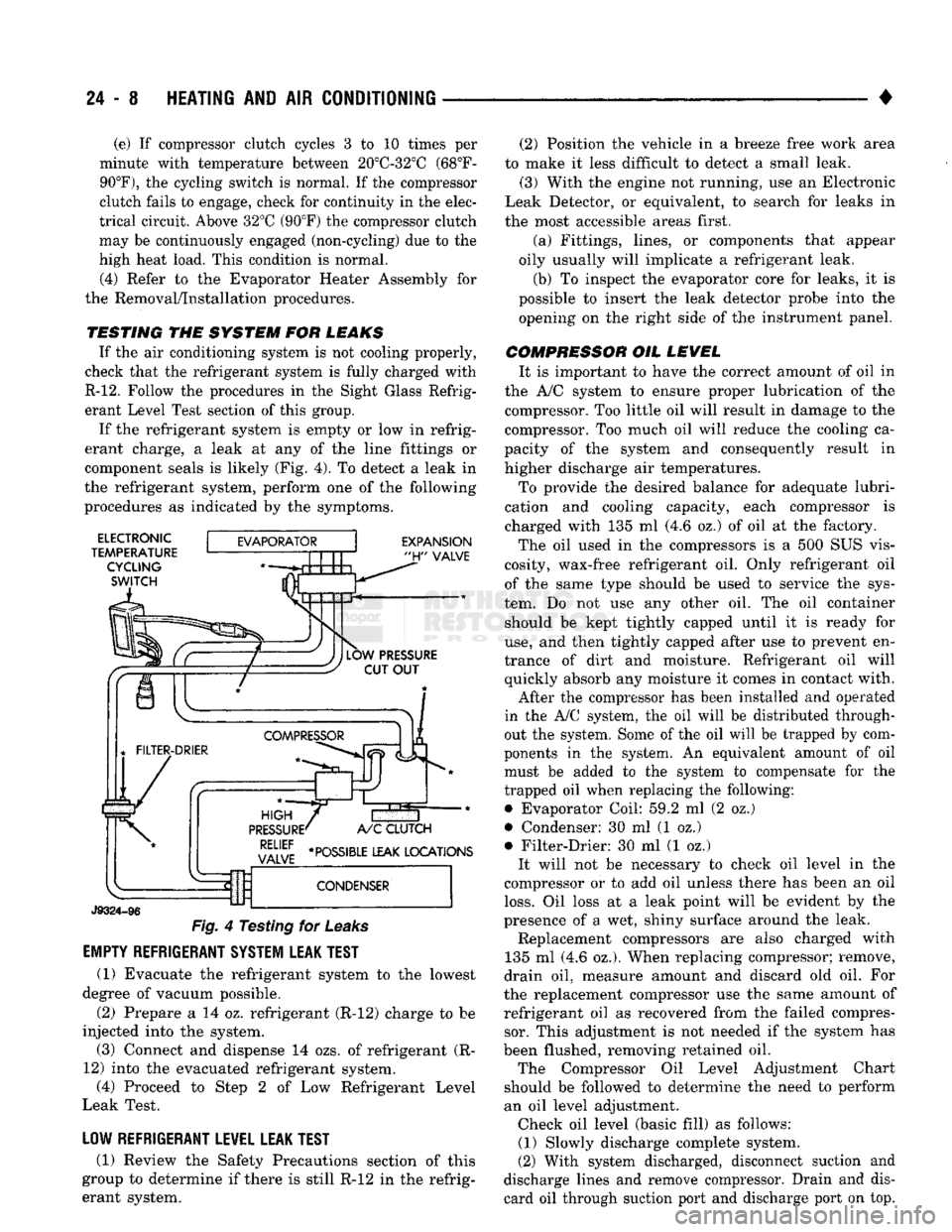
erant charge, a leak at any of the line fittings or
component seals is likely (Fig. 4). To detect a leak in
the refrigerant system, perform one of the following
procedures as indicated by the symptoms.
ELECTRONIC
TEMPERATURE CYCLING
SWITCH
EXPANSION
"H"
VALVE
J9324-96
Fig.
4 Testing for
Leaks
EMPTY REFRIGERANT SYSTEM LEAK TEST
(1) Evacuate the refrigerant system to the lowest
degree of vacuum possible.
(2) Prepare a 14 oz. refrigerant (R-12) charge to be
injected into the system. (3) Connect and dispense 14 ozs. of refrigerant (R-
12) into the evacuated refrigerant system, (4) Proceed to Step 2 of Low Refrigerant Level
Leak Test.
LOW REFRIGERANT LEVEL LEAK TEST
(1) Review the Safety Precautions section of this
group to determine if there is still R-12 in the refrig
erant system. (2) Position the vehicle in a breeze free work area
to make it less difficult to detect a small leak. (3) With the engine not running, use an Electronic
Leak Detector, or equivalent, to search for leaks in
the most accessible areas first.
(a) Fittings, lines, or components that appear
oily usually will implicate a refrigerant leak.
(b) To inspect the evaporator core for leaks, it is
possible to insert the leak detector probe into the opening on the right side of the instrument panel.
COMPRESSOR OIL LEVEL It is important to have the correct amount of oil in
the A/C system to ensure proper lubrication of the compressor. Too little oil will result in damage to the
compressor. Too much oil will reduce the cooling ca
pacity of the system and consequently result in
higher discharge air temperatures.
To provide the desired balance for adequate lubri
cation and cooling capacity, each compressor is
charged with 135 ml (4.6 oz.) of oil at the factory.
The oil used in the compressors is a 500 SUS vis
cosity, wax-free refrigerant oil. Only refrigerant oil of the same type should be used to service the sys
tem. Do not use any other oil. The oil container should be kept tightly capped until it is ready for
use,
and then tightly capped after use to prevent en
trance of dirt and moisture. Refrigerant oil will quickly absorb any moisture it comes in contact with.
After the compressor has been installed and operated
in the A/C system, the oil will be distributed through
out the system. Some of the oil will be trapped by com
ponents in the system. An equivalent amount of oil
must be added to the system to compensate for the
trapped oil when replacing the following: • Evaporator Coil: 59.2 ml (2 oz.)
• Condenser: 30 ml (1 oz.)
• Filter-Drier: 30 ml (1 oz.) It will not be necessary to check oil level in the
compressor or to add oil unless there has been an oil
loss.
Oil loss at a leak point will be evident by the
presence of a wet, shiny surface around the leak. Replacement compressors are also charged with
135 ml (4.6 oz.). When replacing compressor; remove,
drain oil, measure amount and discard old oil. For
the replacement compressor use the same amount of refrigerant oil as recovered from the failed compressor. This adjustment is not needed if the system has
been flushed, removing retained oil. The Compressor Oil Level Adjustment Chart
should be followed to determine the need to perform
an oil level adjustment. Check oil level (basic fill) as follows: (1) Slowly discharge complete system.
(2) With system discharged, disconnect suction and
discharge lines and remove compressor. Drain and dis card oil through suction port and discharge port on top.