1993 DODGE TRUCK fuse
[x] Cancel search: fusePage 194 of 1502
•
BRAKES
i - 7
BRAKE
ADJUSTMENTS-BRAKE
BLEEDING
INDEX
page
Brake
Fluid and Level 7
Brake
System
Bleeding 8
Rear
Brake
Adjustment 7
BRAKE
FLUID
AND
LEWEL
RECOMMENDED
FLUID The only brake fluid recommended for AD models
is Mopar brake fluid, or an equivalent fluid meeting SAE
J1703
and DOT 3 standards.
Use new brake fluid only, to top off the master
cylinder or refill the system* Never use re
claimed fluid, fluid not meeting the
SAE/DOT
standards, fluid marked 70R1, or fluid from a
container that has been left open for any length
of time. Using non recommended or unspecified
fluid can result in brake failure after hard pro longed braking.
BRAKE
FLUID
LEWEL Always clean the master cylinder cover before
checking fluid level. If not cleaned, dirt from the
cover could enter the fluid. Also check the cover seal
and replace it if torn or distorted.
Correct fluid level is to the bottom of the ring in
dicators on models with a plastic reservoir and to
within 1/4 inch of the reservoir rim on all others. If necessary, add fluid to bring up to the proper level.
Note that on disc brake equipped vehicles, fluid level can be expected to fall as the brake pads wear.
BRAKE
FLUID
CONTAMINATION
Oil in the fluid will cause brake system rubber
seals to soften and swell. The seals may also become
porous and begin to deteriorate.
If fluid contamination is suspected, drain off a sam
ple from the master cylinder. A suction gun or simi lar device can be used for this purpose.
Empty the drained fluid into a glass container.
Contaminants in the fluid will cause the fluid to sep
arate into distinct layers. If contamination has oc
curred, the system rubber seals, hoses and cups must
be replaced and the system thoroughly flushed with clean brake fluid.
Remember that brake fluid tends to darken
over time. Do not confuse this normal condition
with contamination.
REAR
BRAKE
ADJUSTMENT
The rear drum brakes are equipped with a self ad
justing mechanism. Under normal circumstances, the only time adjustment is required is when the brake-
page
Stop
Light Switch Adjustment 9
Wheel
Nut Tightening 9
shoes are replaced; removed for access to other parts; or when one or both drums are replaced.
Adjustment can be performed with a standard
brake gauge or with adjusting tool C-3784.
ADJUSTMENT
WITH
STANDARD
BRAKE
GAUGE
(1) Verify that left/right automatic adjuster lever
and cable are properly connected and that parking
brakes are fully released. Be sure there is slack in cables.
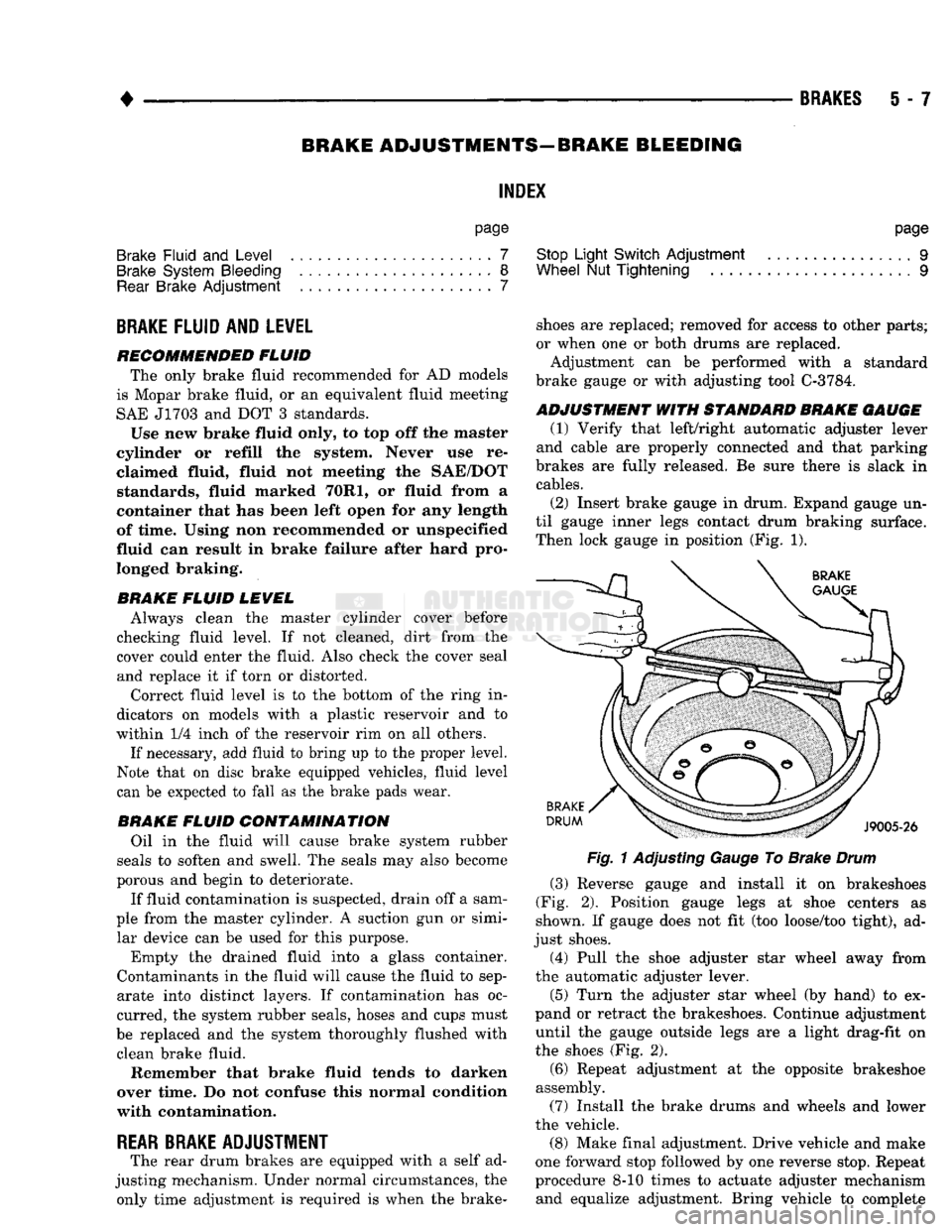
(2) Insert brake gauge in drum. Expand gauge un
til gauge inner legs contact drum braking surface. Then lock gauge in position (Fig. 1).
Fig.
1 Adjusting Gauge To Brake
Drum
(3) Reverse gauge and install it on brakeshoes
(Fig. 2). Position gauge legs at shoe centers as
shown. If gauge does not fit (too loose/too tight), ad
just shoes. (4) Pull the shoe adjuster star wheel away from
the automatic adjuster lever.
(5) Turn the adjuster star wheel (by hand) to ex
pand or retract the brakeshoes. Continue adjustment until the gauge outside legs are a light drag-fit on
the shoes (Fig. 2).
(6) Repeat adjustment at the opposite brakeshoe
assembly. (7) Install the brake drums and wheels and lower
the vehicle.
(8) Make final adjustment. Drive vehicle and make
one forward stop followed by one reverse stop. Repeat
procedure 8-10 times to actuate adjuster mechanism and equalize adjustment. Bring vehicle to complete
Page 200 of 1502
•
BRAKES
5 - 13
COMBINATION VALVE OPERATION
METERING (HOLD-OFF) VALVE The metering valve is used to balance brake action
between the front disc and rear drum brakes. The
valve meters (holds-off) full apply pressure to the front disc brakes until the rear brakeshoes are in full
contact with the drums.
The valve is designed to maintain front brake fluid
pressure at 3-30 psi until the hold-off limit of 117 psi is reached. At this point, the metering valve opens completely permitting full fluid apply pressure to the
front disc brakes.
PRESSURE DIFFERENTIAL SWITCH AND VALVE The pressure differential switch is connected to the
brake warning light. The switch is triggered by movement of the switch valve. The purpose of the switch is to monitor fluid pressure in the separate
front/rear brake hydraulic circuits.
A decrease or loss of fluid pressure in either hy
draulic circuit will cause the switch valve to shuttle
forward or rearward in response to a pressure differ ential.
Movement of the switch valve will push the switch
plunger upward. This closes the switch internal con tacts completing the electrical circuit to the warning light. The switch valve will remain in an actuated
position until repair restores system pressures to nor mal levels.
COMBINATION VALVE TESTING
TESTING METERING VALVE Metering valve operation can be checked visually
and with the aid of a helper.
Observe the metering valve stem while a helper
applies and releases the brakes. If the valve is oper
ating correctly, the stem will extend slightly when
the brakes are applied and retract when the brakes are released.
If the valve is faulty, replace the entire combina
tion valve as an assembly.
TESTING PRESSURE DIFFERENTIAL SWITCH (1) Have helper sit in drivers seat to observe brake
warning light and to operate brake pedal.
(2) Raise vehicle on hoist.
(3) Connect bleed hose to left or right rear wheel
cylinder. Then immerse hose end in glass jar par
tially filled with brake fluid.
(4) Have helper press and hold brake pedal all the
way down and observe warning light.
(a) If warning light illuminates, switch is operat
ing correctly. (b) If light fails to illuminate, check circuit fuse,
bulb and wiring. Repair as necessary and repeat test steps (3) and (4). (5) If warning light still fails to illuminate, check
brakelight and park brake switches (and wiring) with test lamp. Repair or replace parts as necessary and test differential pressure switch operation again.
(6) If warning light still does not illuminate,
switch is faulty. Replace combination valve, bleed
brakes and verify proper switch and valve operation.
COMBINATION VALVE REMOVAL/INSTALLATION
VALVE REMOVAL (1) Raise vehicle on hoist.
(2) Mark or tag brake lines connected to valve for
assembly reference.
(3) Disconnect lines at valve (Fig. 8).
(4) Disconnect wires from differential pressure
switch.
(5) Remove bolts attaching valve to frame bracket
and remove valve.
VALVE INSTALLATION (1) Mount new valve on bracket and tighten valve
and bracket screws/nuts securely.
(2) Connect brakelines to valve. Tighten fittings to
16 N*m (145 in. lbs.)
(3) Connect wires to pressure differential switch
terminal. (4) Bleed brakes.
(5) Lower vehicle and verify proper brake opera
tion.
BRAKE
LINES AND
HOSES
BRAKE LINE AND HOSE INSPECTION Flexible rubber hose is used at both front brakes
and at the rear axle junction block. Inspect the hoses
whenever the brake system is serviced, at every en gine oil change, or whenever the vehicle is in for ser
vice.
Inspect the hoses for surface cracking, scuffing, or
worn spots. Replace any brake hose immediately if
the fabric casing of the hose is exposed by cracks or abrasion.
Also check brake hose installation. Faulty installa
tion can result in kinked, twisted hoses, or contact with the wheels and tires or other chassis compo
nents.
All of these conditions can lead to scuffing,
cracking and eventual failure.
The steel brake lines should be inspected periodi
cally for evidence of corrosion, twists, kinks, leaks, or
other damage. Heavily corroded lines will eventually
rust through causing leaks. In any case, corroded or damaged brake lines should be replaced.
Page 250 of 1502
•
BRAKES
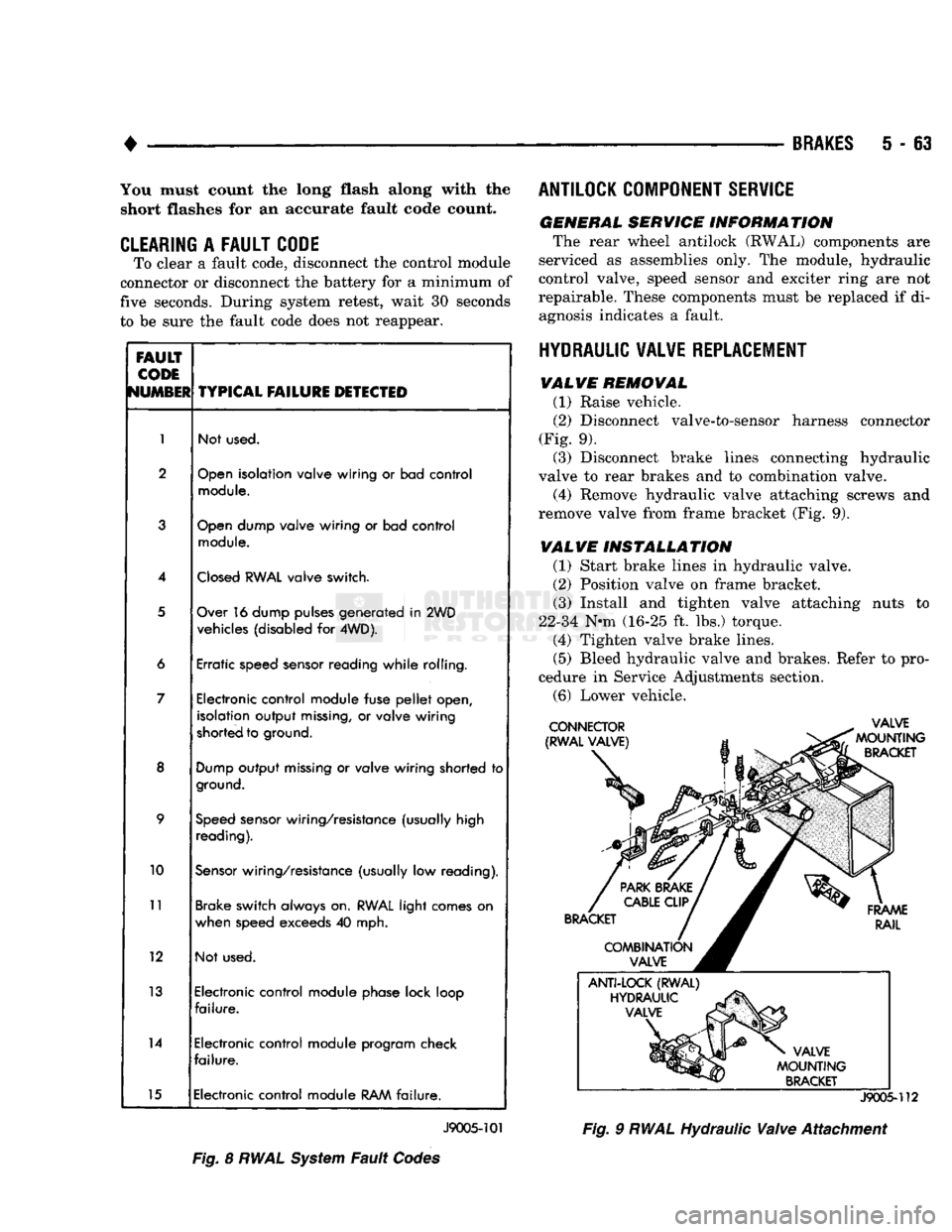
5 - 63 You must count the long flash along with the
short flashes for an accurate fault code count.
CLEARING
A
FAULT CODE
To clear a fault code, disconnect the control module
connector or disconnect the battery for a minimum of
five seconds. During system retest, wait 30 seconds
to be sure the fault code does not reappear.
FAULT
CODE
NUMBER
TYPICAL
FAILURE
DETECTED
1
Not used.
2
Open
isolation valve wiring
or
bad control
module.
3
Open
dump valve wiring
or
bad control
module.
4
Closed
RWAL
valve switch.
5
Over 16 dump pulses generated
in
2WD
vehicles (disabled
for
4WD).
6 Erratic speed sensor reading while rolling.
7 Electronic control module fuse
pellet
open,
isolation output
missing,
or
valve wiring
shorted to ground.
8
Dump
output
missing
or
valve wiring shorted
to
ground.
9
Speed
sensor wiring/resistance (usually high
reading).
10
Sensor
wiring/resistance (usually
low
reading).
11
Brake switch always on.
RWAL
light comes
on
when speed exceeds
40
mph.
12 Not used.
13 Electronic control module phase lock loop
failure.
14 Electronic control module program check
failure.
15 Electronic control module
RAM
failure.
J9005-101
Fig.
8
RWAL
System
Fault
Codes ANTILOCK COMPONENT SERVICE
GENERAL SERVICE INFORMATION
The rear wheel antilock (RWAL) components are
serviced as assemblies only. The module, hydraulic
control valve, speed sensor and exciter ring are not
repairable. These components must be replaced if di agnosis indicates a fault.
HYDRAULIC VALVE REPLACEMENT VALVE REMOVAL
(1) Raise vehicle.
(2)
Disconnect valve-to-sensor harness connector
(Fig. 9). (3) Disconnect brake lines connecting hydraulic
valve to rear brakes and to combination valve.
(4) Remove hydraulic valve attaching screws and
remove valve from frame bracket (Fig. 9).
VALVE INSTALLATION
(1) Start brake lines in hydraulic valve.
(2)
Position valve on frame bracket. (3) Install and tighten valve attaching nuts to
22-34 N-m (16-25 ft. lbs.) torque. (4) Tighten valve brake lines.
(5)
Bleed hydraulic valve and brakes. Refer to pro
cedure in Service Adjustments section.
(6)
Lower vehicle.
J9005-112
Fig.
9
RWAL
Hydraulic
Valve
Attachment
Page 325 of 1502
8A
- 4
ELECTRICAL
•
IGNITION
OFF
DRAW
(IOD)
Ignition off draw refers to power being drained
from the battery with the ignition turned off. A nor
mal vehicle electrical system will draw from 5 to 20
milliamps. A vehicle that has not been operated for
an extended period of time (approximately 20 days)
may discharge the battery to an inadequate level.
Battery drain should not exceed approximately 20
MA (20 milliamps = 0.020 amps). The 20 MA are needed to supply PCM memory,
digital clock memory, and ETR (electronically tuned
radio) memory. Excessive battery drain is caused by items left
turned on, internally shorted generator, or intermit
tent short in wiring.
If the IOD is excessive (over 20 milliamperes), the
defect must be found and corrected before replacing a
battery. In most cases the battery can be charged and returned to service.
TEST PROCEDURE Testing for higher amperage IOD must be per
formed first to prevent damage to most milliamp
meters.
Verify that all electrical accessories are OFF. Turn
off all lights, remove ignition key, and close all
doors.
If the vehicle is equipped with electronic acces
sories (illuminated entry, high line radio), allow the
systems to automatically shut off (time out), up to 3
minutes.
(1) After determining that the underhood lamp is
operating properly then disconnect bulb. (2) Disconnect negative cable from battery.
(3) Connect a typical 12 volt test light (low watt
age bulb) between the negative cable clamp and the
battery negative terminal. The test light may light brightly for up to 3 min
utes or may not light at all (depending on the elec
trical equipment). The term brightly being used
throughout the following tests, implies the bright ness of the test light will be the same as if it were
connected across the battery.
The test light must be securely clamped to the neg
ative cable and battery terminal. If the test light be
comes disconnected during any of the IOD test, the electronic timer function will be activated and all
tests must be repeated.
(4) After 3 minutes, the test light should turn OFF
or be DIMLY lit (depending on the electrical equip
ment).
If the test light remains brightly lit do not
disconnect it. Remove each fuse or circuit breaker (refer to Group 8 - Wiring Diagrams) until test light
is either OFF or DIMLY lit. This will eliminate the
higher amperage draw.
If test light is still bright after disconnecting each
fuse and circuit breaker, disconnect the wiring har ness from the generator. Refer to Generator Testing
in this group. Do not disconnect the test light. After higher amperage IOD has been corrected, low
amperage IOD may be checked.
It is now safe to install milliamp meter to check for
low amperage IOD.
(5) With test light still connected, securely clamp
an ammeter between battery negative terminal and
negative battery cable.
If the test light or the milliamp meter circuit is
broken the various timer circuits will start. Do
not open any doors or turn on any electrical ac cessories with the test light disconnected or the
meter may be damaged.
(6) Disconnect test light. The current draw should
not exceed 0.020 amp. If it exceeds 20 milliamps iso
late each circuit by removing circuit breakers and
fuses.
The meter reading drops once the high current
problem is found. Repair this section of the circuit,
whether it is a wiring short or component failure.
BATTERY
OPEN CIRCUIT VOLTAGE TEST
A battery voltage (no load) test will indicate the
state of charge of a battery that will pass the Battery
Load Test described in this section. Before proceed
ing with this test or the Battery Load Test the
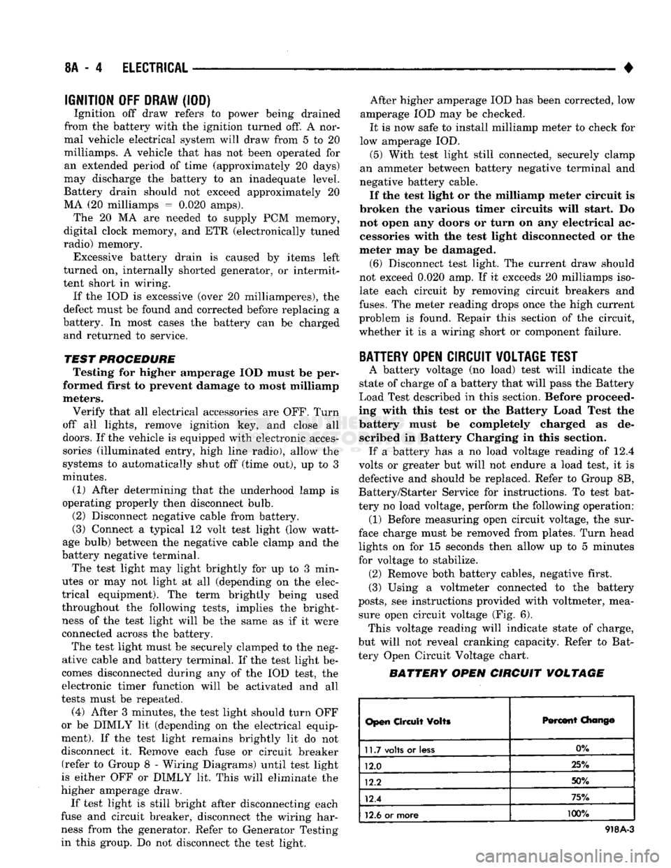
battery must be completely charged as de scribed in Battery Charging in this section. If a battery has a no load voltage reading of 12.4
volts or greater but will not endure a load test, it is
defective and should be replaced. Refer to Group 8B,
Battery/Starter Service for instructions. To test bat
tery no load voltage, perform the following operation: (1) Before measuring open circuit voltage, the sur
face charge must be removed from plates. Turn head lights on for 15 seconds then allow up to 5 minutes
for voltage to stabilize. (2) Remove both battery cables, negative first.
(3) Using a voltmeter connected to the battery
posts,
see instructions provided with voltmeter, mea sure open circuit voltage (Fig. 6). This voltage reading will indicate state of charge,
but will not reveal cranking capacity. Refer to Bat
tery Open Circuit Voltage chart.
BATTERY OPEN CIRCUIT VOLTAGE
Open
Circuit
Volts
Percent
Chang©
11.7
volts
or
less
0%
12.0 25%
12.2 50%
12.4 75%
12.6
or more 100%
918A-3
Page 334 of 1502
•
ELECTRICAL
8A - 13 GENERATOR TEST PROCEDURES ON
VEHICLE
INDEX
page
Current
Output
Test
......................
14
Diagnostic Procedures
13
General
Information
13
Generator
Output
Wire Resistance Test
.......
13
page
How
to
Use
Malfunction
Indicator
(Check Engine) Lamp
for
Fault
Codes
17
Operational Check
with
Voltmeter
............
13
Using
On-Board Diagnostic System
15
GENERAL
INFORMATION
The generator
is
belt-driven
by the
engine.
All en
gines
use
serpentine drive. The amount
of DC
current produced
by the
gener
ator
is
controlled
by the
Powertrain Control Module (PCM).
All vehicles
are
equipped with
On
Board Diagnos
tics (OBD).
All OBD
sensing systems
are
monitored
by
the PCM. The PCM
will store
in
electronic mem ory
any
detectable failure within
the
monitored cir
cuits.
Refer
to
USING ON-BOARD DIAGNOSTIC SYSTEM
in
this group
for
more information.
OPERATIONAL CHECK
WITH
VOLTMETER
When
the
ignition switch
is
turned
to the RUN po
sition, battery potential will register
on the
voltme
ter. During engine cranking
a
lower voltage will appear
on the
meter. With
the
engine running,
a
voltage reading higher than
the
first reading (igni
tion
in RUN)
should register.
DIAGNOSTIC PROCEDURES
If
the
indicator does
not
operate properly,
or if an
undercharged
or
overcharged battery condition
oc
curs,
the
following procedures
may be
used
to
diag
nose
the
charging system. Remember that
an
undercharged battery
is
often
caused
by:
• accessories being left
on
overnight
•
or by a
defective switch which allows
a
bulb, such
as a
trunk
or
glove
box
light,
to
stay
on
(refer
to
Ignition
Off
Draw).
WISUAL
INSPECTION
• Inspect condition
of
battery cable terminals, bat
tery posts, connections
at
engine block, starter motor solenoid
and
relay. They should
be
clean
and
tight.
Repair
as
required.
• Inspect
all
fuses
in the
fuse block
for
tightness
in
receptacles. They should
be
properly installed
and
tight. Repair
or
replace
as
required.
• Inspect generator mounting bolts
for
tightness.
Re
place
or
torque bolt
as
required (refer
to
Torque Specifications).
• Inspect generator drive belt condition
and
tension.
Tension
or
replace belt
as
required. Refer
to
Belt
Tension Specifications. • Inspect connection
at
generator
B+
output.
It
should
be
clean
and
tight. Repair
as
required.
GENERATOR
OUTPUT
WIRE RESISTANCE TEST
(FIG.
1)
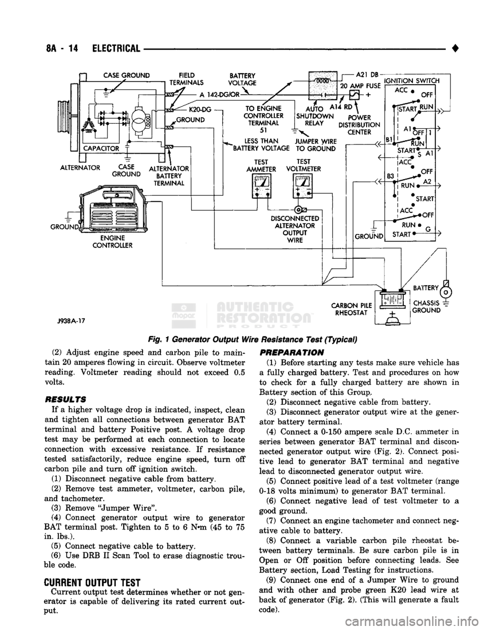
Generator output wire resistance test will show
amount
of
voltage drop across generator output wire
between generator
BAT
terminal
and
battery posi tive post.
PREPARATION
(1) Before starting test make sure vehicle
has a
fully charged battery. Test
and
procedures
on how to
check
for a
fully charged battery
are
shown
in
Bat
tery section
of
this Group.
(2) Turn
OFF
ignition switch.
(3)
Disconnect negative cable from battery.
(4)
Disconnect generator output wire from genera
tor output Battery terminal. (5) Connect
a 0-150
ampere scale
D.C.
ammeter
in
series between generator
BAT
terminal
and
discon
nected generator output wire. Connect Positive lead
to generator
BAT
terminal
and
Negative lead
to
dis connected generator output wire. (6) Connect Positive lead
of a
test voltmeter
(Range
0-18
volts minimum)
to
disconnected genera
tor output wire. Connect negative lead
of
test voltme
ter
to
battery positive cable
at
positive post. (7) Connect
one end of a
Jumper Wire
to
ground
and with other
end
probe green
K20
lead wire
at
back
of
generator
(Fig. 1).
(This will generate
a
fault
code).
CAUTION:
Do not
connect blue
A142
lead
of
wiring
to ground. Refer
to
Group
8W
-
Wiring Diagrams
for
more information.
(8) Connect
an
engine tachometer
and
connect neg
ative cable
to
battery.
(9) Connect
a
variable carbon pile rheostat
be
tween battery terminals.
Be
sure carbon pile
is in
"Open"
or "Off
position before connecting leads.
See
Battery Section, Load Testing
for
instructions.
TEST
(1) Start engine. Immediately after starting,
re
duce engine speed
to
idle.
Page 335 of 1502
8A
- 14
ELECTRICAL
CASE
GROUND
FIELD
TERMINALS
142-DG/OR
BATTERY
VOLTAGE
ALTERNATOR
CASE
GROUND
GROUND ALTERNATOR
BATTERY
TERMINAL
ENGINE
CONTROLLER TO ENGINE
CONTROLLER TERMINAL
51
LESS
THAN
"BATTERY VOLTAGE
m^mm i
A21 DB-
20
AMP FUSE
A14
RD
AUTO
SHUTDOWN
RELAY
IGNITION
SWITCH
POWER
DISTRIBUTION
CENTER
JUMPER WIRE TO GROUND TEST
AMMETER TEST
VOLTMETER
2
i
DISCONNEaED
ALTERNATOR
OUTPUT
WIRE
ACC
OFF
J938A-17
CARBON
PILE
RHEOSTAT
Fig.
1 Generator Output
Wire
Resistance
Test
(Typical)
(2) Adjust engine speed and carbon pile to main
tain 20 amperes flowing in circuit. Observe voltmeter
reading. Voltmeter reading should not exceed 0.5
volts.
RESULTS
If a higher voltage drop is indicated, inspect, clean
and tighten all connections between generator BAT
terminal and battery Positive post. A voltage drop
test may be performed at each connection to locate
connection with excessive resistance. If resistance
tested satisfactorily, reduce engine speed, turn off carbon pile and turn off ignition switch.
(1) Disconnect negative cable from battery.
(2) Remove test ammeter, voltmeter, carbon pile,
and tachometer. (3) Remove "Jumper Wire".
(4) Connect generator output wire to generator
BAT terminal post. Tighten to 5 to 6 Nnn (45 to 75
in.
lbs.). (5) Connect negative cable to battery.
(6) Use DRB II Scan Tool to erase diagnostic trou
ble code.
CURRENT
OUTPUT
TEST
Current output test determines whether or not gen
erator is capable of delivering its rated current out
put.
PREPARATION
(1) Before starting any tests make sure vehicle has
a fully charged battery. Test and procedures on how
to check for a fully charged battery are shown in
Battery section of this Group,
(2) Disconnect negative cable from battery.
(3) Disconnect generator output wire at the gener
ator battery terminal.
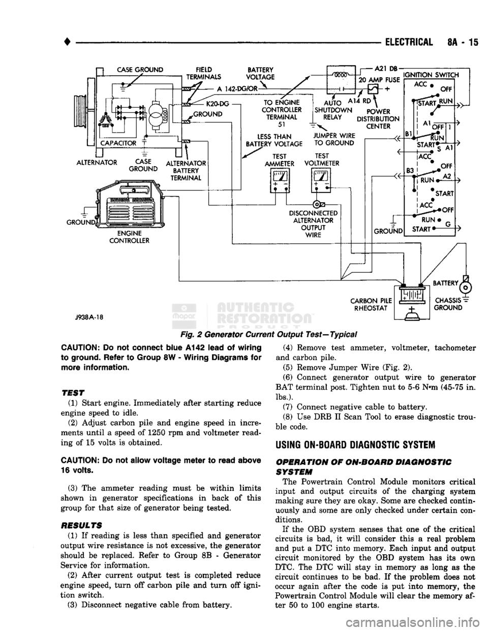
(4) Connect a 0-150 ampere scale D.C. ammeter in
series between generator BAT terminal and discon
nected generator output wire (Fig. 2). Connect posi
tive lead to generator BAT terminal and negative
lead to disconnected generator output wire.
(5) Connect positive lead of a test voltmeter (range
0-18 volts minimum) to generator BAT terminal.
(6) Connect negative lead of test voltmeter to a
good ground.
(7) Connect an engine tachometer and connect neg
ative cable to battery.
(8) Connect a variable carbon pile rheostat be
tween battery terminals. Be sure carbon pile is in Open or Off position before connecting leads. See
Battery section, Load Testing for instructions.
(9) Connect one end of a Jumper Wire to ground
and with other and probe green K20 lead wire at
back of generator (Fig. 2). (This will generate a fault
code).
Page 336 of 1502
•
ELECTRICAL
8A - 15 a
CASE
GROUND
CAPACITOR
ALTERNATOR ~L FIELD
TERMINALS
A
142-DG/OR BATTERY
VOLTAGE K20-DG
—!
GROUND
CASE
GROUND
til
ALTERNATOR BATTERY
TERMINAL ENGINE
CONTROLLER TO ENGINE
CONTROLLER TERMINAL
51
LESS
THAN
BATTERY VOLTAGE A21
DB-
.....
IGNITION SWITCH
20 AMP FUSE
AUTO
AH ^
SHUTDOWN POWER
RELAY
DISTRIBUTION
\
CENTER TEST
AMMETER JUMPER WIRE
TO GROUND
TEST
VOLTMETER
GO
5—n
DISCONNECTED
ALTERNATOR OUTPUT WIRE GROUND
ACC
Bl
OFF
RUN OFF
START*T
|ACC
CARBON
PILE RHEOSTAT
J938A-18
Fig.
2 Generator Current Output Test—Typical
CAUTION:
Do not
connect
blue
A142
lead
of
wiring
to ground.
Refer
to
Group
8W -
Wiring
Diagrams
for
more
information.
TEST
(1) Start engine. Immediately after starting reduce
engine speed to idle. (2) Adjust carbon pile and engine speed in incre
ments until a speed of 1250 rpm and voltmeter read
ing of 15 volts is obtained.
CAUTION:
Do not
allow
voltage
meter
to
read
above
16 volts.
(3) The ammeter reading must be within limits
shown in generator specifications in back of this
group for that size of generator being tested.
RESULTS
(1) If reading is less than specified and generator
output wire resistance is not excessive, the generator
should be replaced. Refer to Group 8B - Generator
Service for information.
(2) After current output test is completed reduce
engine speed, turn off carbon pile and turn off igni
tion switch.
(3) Disconnect negative cable from battery. (4) Remove test ammeter, voltmeter, tachometer
and carbon pile. (5) Remove Jumper Wire (Fig. 2).
(6) Connect generator output wire to generator
BAT terminal post. Tighten nut to 5-6 Nnn (45-75 in.
lbs.).
(7) Connect negative cable to battery.
(8) Use DRB II Scan Tool to erase diagnostic trou
ble code.
USING
ON-BOARD
DIAGNOSTIC
SYSTEM
OPERATION
OF
ON-BOARD
DIAGNOSTIC
SYSTEM
The Powertrain Control Module monitors critical
input and output circuits of the charging system
making sure they are okay. Some are checked contin
uously and some are only checked under certain con
ditions.
If the OBD system senses that one of the critical
circuits is bad, it will consider this a real problem
and put a DTC into memory. Each input and output
circuit monitored by the OBD system has its own
DTC.
The DTC will stay in memory as long as the
circuit continues to be bad. If the problem does not
occur again after the code is put into memory, the
Powertrain Control Module will clear the memory af
ter 50 to 100 engine starts.
Page 394 of 1502
INSTRUMENT PANEL
AND
GAUGES
8E - 13
INSTRUMENT
PANEL MAP LAMP
BRACKET
HEADLAMP
SWITCH
CLUSTER
ASSEMBLY
HEADLAMP
SWITCH
MOUNTING
NUT CARGO LAMP
SWITCH
BEZEL
AND
APPLIQUE
HEADLAMP
KNOB
AND
STEM
BRACKET-AAAP LAMP
MOUNTING
Fig.
2 Instrument
Panel
(6) Position lower steering cover and install 4
screws.
(7)
Install bezel.
(8)
Remove protective cover from steering column.
(9) Connect negative cable to battery. (10) Check to see that all instruments are func
tioning properly.
PRINTED CIRCUIT BOARD
A visual inspection of the conductors should be
made for cracks or damaged circuits. If no visual
damage is evident, each circuit should be tested for continuity with an ohmmeter or a test light. Should an open circuit be detected, the printed circuit board
should be replaced.
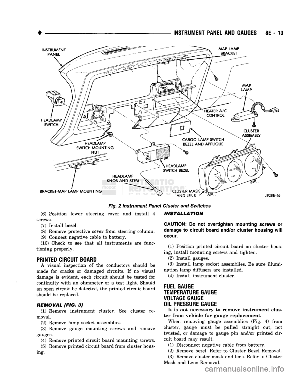
REMOVAL (FIG. 3J (1) Remove instrument cluster. See cluster re
moval.
(2)
Remove lamp socket assemblies.
(3) Remove gauge mounting screws and remove
gauges.
(4) Remove printed circuit board mounting screws.
(5)
Remove printed circuit board from cluster hous
ing.
HEADLAMP
SWITCH
BEZEL
CLUSTER MASK AND LENS
J928E-46
Cluster
and
Switches
INSTALLATION
CAUTION:
Do not overtighten mounting
screws
or
damage
to circuit
board
and/or
cluster
housing
will
occur.
(1) Position printed circuit board on cluster hous
ing, install mounting screws and tighten.
(2)
Install gauges.
(3) Install lamp socket assemblies. Be sure illumi
nation lamp diffusers are installed. (4) Install instrument cluster.
FUEL GAUGE
TEMPERATURE
GAUGE VOLTAGE GAUGE
OIL
PRESSURE
GAUGE
It is not necessary to remove instrument clus
ter from vehicle for gauge replacement. When removing gauge assemblies (Fig. 4) from
cluster, gauge must be pulled straight out, not
twisted, or damage to gauge pin and/or printed cir cuit board may result. (1) Disconnect negative cable from battery.
(2)
Remove bezel. Refer to Cluster Bezel Removal. (3) Remove cluster mask and lens. Refer to Cluster
Mask and Lens Removal.