1993 DODGE TRUCK driver seat adjustment
[x] Cancel search: driver seat adjustmentPage 171 of 1502
3
- 44
REAR SUSPENSION
AND
AXLE
— __—_ . _ •
SPECIAL
TOOL
SET
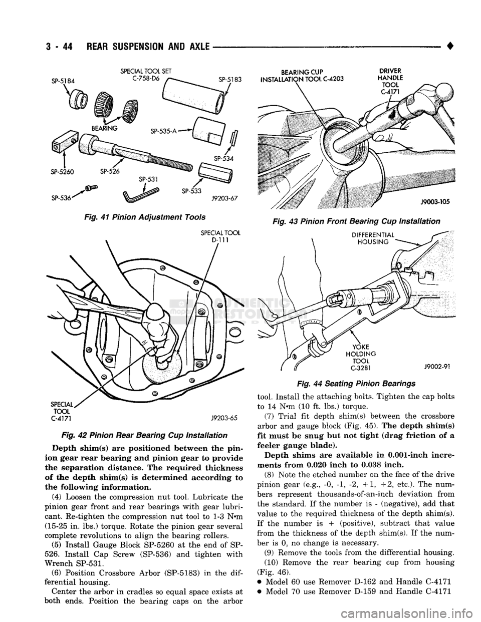
Fig.
41
Pinion
Adjustment Tools
SPECIAL
TOOL
C-4171
J9203-65
Fig.
42
Pinion
Rear Bearing Cup
Installation
Depth shim(s) are positioned between the pin
ion gear rear bearing and pinion gear to provide
the separation distance. The required thickness of the depth shim(s) is determined according to
the following information.
(4) Loosen the compression nut tool. Lubricate the
pinion gear front and rear bearings with gear lubri cant. Re-tighten the compression nut tool to 1-3 N-m (15-25 in. lbs.) torque. Rotate the pinion gear several
complete revolutions to align the bearing rollers.
(5) Install Gauge Block SP-5260 at the end of SP-
526.
Install Cap Screw (SP-536) and tighten with
Wrench
SP-531.
(6) Position Crossbore Arbor (SP-5183) in the
dif
ferential housing. Center the arbor in cradles so equal space exists at
both ends. Position the bearing caps on the arbor
BEARING
CUP DRIVER
INSTALLATION
TOOL
C-4203
HANDLE
Fig.
44 Seating
Pinion
Bearings
tool. Install the attaching bolts. Tighten the cap bolts
to 14 N-m (10 ft. lbs.) torque.
(7) Trial fit depth shim(s) between the crossbore
arbor and gauge block (Fig. 45). The depth shim(s)
fit must be snug but not tight (drag friction of a
feeler gauge blade).
Depth shims are available in 0.001-inch incre
ments from 0.020 inch to 0.038 inch.
(8) Note the etched number on the face of the drive
pinion gear (e.g., -0, -1, -2, +1, +2, etc.). The num
bers represent thousands-of-an-inch deviation from the standard. If the number is - (negative), add that
value to the required thickness of the depth shim(s).
If the number is + (positive), subtract that value
from the thickness of the depth shim(s). If the num
ber is 0, no change is necessary.
(9) Remove the tools from the differential housing.
(10) Remove the rear bearing cup from housing
(Fig. 46),
* Model 60 use Remover D-162 and Handle C-4171 *> Model 70 use Remover D-159 and Handle C-4171
Page 195 of 1502
i - 8
BRAKES
•
BRAKE
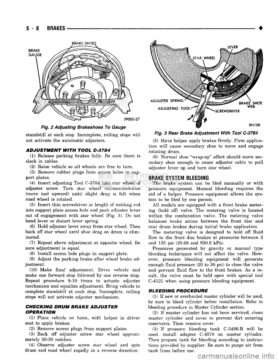
SHOE'S
Fig. 2 Adjusting Brakeshoes To Gauge standstill at each stop. Incomplete, rolling stops will
not activate the automatic adjusters.
ADJUSTMENT
WITH
TOOL
C-3784
(1) Release parking brakes fully. Be sure there is
slack in cables. (2) Raise vehicle so all wheels are free to turn.
(3) Remove rubber plugs from access holes in sup
port plates. (4) Insert adjusting Tool
0-3784
into star wheel of
adjuster screw. Turn star wheel counterclockwise
(move tool upward) until slight drag is felt when
road wheel is rotated.
(5)
Insert thin screwdriver or length of welding rod
into support plate access hole and push adjuster lever
out of engagement with star wheel (Fig. 3). Do not
bend lever or distort lever spring.
(6) Hold adjuster lever away from star wheel. Then
back off star wheel until shoe drag on drum is elim inated.
(7) Repeat above adjustment at opposite wheel. Be
sure adjustment is equal. (8) Install access hole plugs in support plate.
(9) Adjust the parking brake after wheel brake ad
justment.
(10) Make final adjustment. Drive vehicle and
make one forward stop followed by one reverse stop.
Repeat procedure 8-10 times to actuate adjuster
mechanism and equalize adjustment. Bring vehicle to
complete standstill at each stop. Incomplete, rolling stops will not activate adjuster mechanism.
CHECKING DRUM
BRAKE ADJUSTER
OPERATION
(1) Place vehicle on hoist, with helper in driver
seat to apply brakes.
(2) Remove access plugs from support plates.
(3) Back off adjuster screw star wheel approxi
mately 20-30 notches. (4) Observe adjuster screw star wheel and spin
drum and road wheel rapidly in a reverse direction. Fig. 3 Rear Brake Adjustment With Tool
C-3784
(5) Have helper apply brakes firmly. Firm applica
tion will cause secondary shoe to move and engage rotating drum.
(6) Normal shoe "wrap-up" effect should move sec
ondary shoe enough to cause adjuster cable to pull adjuster lever up and turn star wheel.
BRAKE
SYSTEM BLEEDING
The brake system can be bled manually or with
pressure equipment. Manual bleeding requires the aid of a helper. Pressure equipment allows the sys
tem to be bled by one person. All models are equipped with a front brake meter
ing (hold off) valve. The metering valve is located
within the combination valve. The metering valve balances brake action between the front disc and
rear drum brakes during initial brake application. The metering valve is designed to hold off fluid
flow to the front disc brakes at pressures between 3 and 135 psi (20.68 and 930.8 kPa). Pressures generated by gravity or manual type
bleeding techniques will not affect the valve. How ever, pressure bleeding equipment will generate
enough fluid pressure (20 to 30 psi) to close the valve and prevent fluid flow to the front brakes. As a re
sult, the valve must be held open with special tool
C-4121 when using pressure bleeding equipment.
BLEEDING PROCEDURE (1) If new or overhauled master cylinder will be used,
be sure to bleed cylinder before installation. Refer to
bleeding procedure in Master Cylinder section. (2) If master cylinder has not been serviced, clean
master cylinder and cover to prevent dirt entering
reservoirs. Then remove cover.
(3) If pressure bleeding tank C-3496-B will be
used, install adapter C-4578 on master cylinder.
Then prepare tank for bleeding according to instruc
tions provided by supplier. Be sure to purge air from
tank lines before use.
Page 243 of 1502
5
- 56
BRAKES
•
PARKING
BRAKES
GENERAL INFORMATION
The parking brake mechanism
on AD
models
is a
three cable system operated
by a
foot pedal assembly
(Figs.
1 and 2).
The foot pedal
is
mounted
on the
driver side cowl
panel.
The
front cable
is
attached
to the
pedal assem
bly.
An
intermediate cable connects
the
front cable
to
the rear cables.
An
equalizer
and
ratio lever connect
the rear cables
to the
intermediate cable.
The
rear
cables
are
connected
to the
secondary brakeshoes
by
a lever attached
to
each shoe.
PARKING BRAKE CABLE ADJUSTMENT
(1) Adjust rear drum brakes before adjusting park
ing brake cables. (2) Release parking brakes fully.
(3) Raise vehicle.
(4) Loosen adjusting
nut on
front cable until there
is slack
in all
cables. (5) Rotate rear wheels
and
tighten cable adjusting
nut until slight drag
is
created
at
wheels.
(6)
Continue rotating rear wheels
and
loosen cable
adjusting
nut
until
all
drag
is
eliminated. (7) Back
off
cable adjusting
nut an
additional
two
full turns.
(8)
Apply parking brake several times.
(9) Release parking brakes. Then verify that rear
wheels rotate freely with
no
evidence
of
drag. (10) Lower vehicle.
REAR
CABLE REPLACEMENT
REAR CABLE
REMOVAL
(1) Release parking brakes fully.
(2) Raise vehicle.
(3) Remove adjusting
nut
from front cable.
(4) Remove rear wheels.
(5) Remove brake drums.
(6)
Remove brakeshoes
and
parking brake strut
and spring. (7) Disconnect cable from parking brake lever
on
secondary brakeshoe.
(8)
Compress cable retainer tabs
and
remove cable
from support plate.
(9) Remove cable from guides
and
retaining clips.
(10) Disconnect cable from equalizer
and
ratio
le
ver.
(11) Remove cable.
REAR CABLE
INSTALLATION
(1) Insert cable through support plate hole
and
seat cable. (2) Connect cable
to
lever
on
secondary brakeshoe.
(3) Install brakeshoes, parking brake strut
and
spring, shoe return
and
holddown springs
and
self
adjuster components.
(4)
Install cable
in
cable guide
and
install cable
re
taining clips,
if
equipped. (5) Connect cable
to
ratio lever
and
equalizer.
(6)
Adjust rear brakes
and
install brake drum
and
wheel. (7) Adjust parking brake cable.
FRONT CABLE REPLACEMENT
FRONT
CABLE
REMOVAL
(1) Remove front cable adjusting
nut.
(2) Remove clip securing cable
to
anchor bracket
and slide cable
out of
bracket.
(3) Remove retainer attaching cable
to
pedal
as
sembly frame.
(4)
Disengage cable from pedal clevis.
(5) Remove cable grommet
(or
seal) from floor
pan.
(6)
Remove front cable.
FRONT
CABLE
INSTALLATION
(1) Insert cable through floor
pan.
(2) Connect cable
to
pedal clevis
and
install cable
retainer.
(3) Seat cable grommet
(or
seal)
in
floorpan.
(4)
Route cable
to
anchor bracket
and
intermediate
cable.
(5)
Secure cable
in
anchor bracket with U-clip.
(6)
Connect cable
to
adjusting link
and
install
ca
ble adjusting
nut.
(7)
Adjust rear brakeshoes,
if
necessary.
(8) Adjust parking brake cable
as
described
in
this
section.
INTERMEDIATE
CABLE REPLACEMENT
(1) Remove adjusting
nut
from front cable.
(2) Disengage intermediate cable from ratio lever
or cable equalizer.
(3)
Remove cable.
(4)
Connect
new
cable
to
ratio lever
or
cable equal
izer.
(5)
Connect cable
to
adjusting link.
(6)
Insert front cable
in
adjusting link
and
install
cable adjusting
nut.
(7)
Adjust brakeshoes
if
necessary.
(8) Adjust parking brake cable
as
described
in
this
section.
Page 987 of 1502
19
-26
STEERING
•
CAUTION:
Do not
turn
stub
shaft
any
further
than
necessary.
The
recirculating
balls
will
drop
out of
the
rack
piston
circuit
and fall
inside
the
rack
pis
ton
chamber.
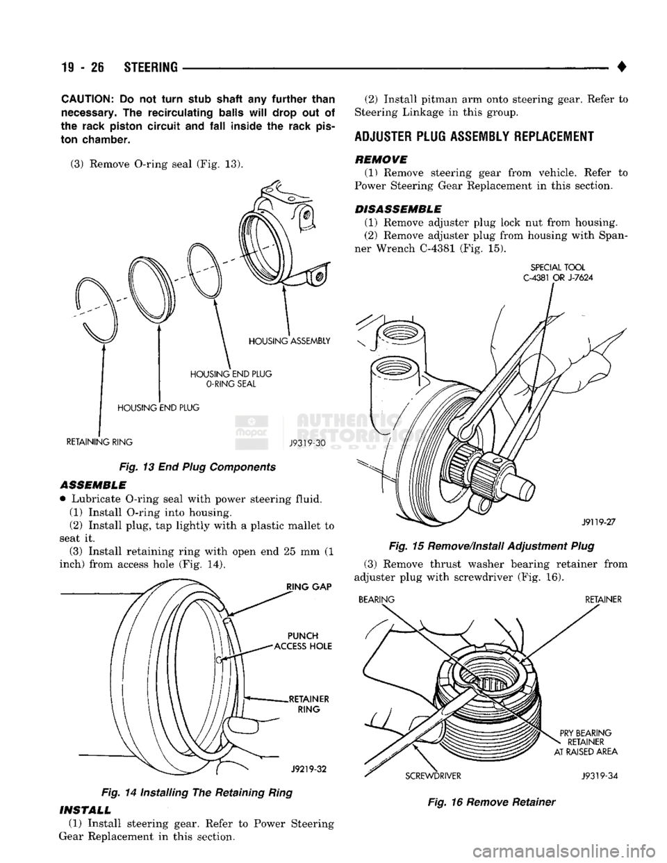
(3) Remove O-ring seal
(Fig. 13).
HOUSING
END
PLUG
O-RING
SEAL
HOUSING
END
PLUG
RETAINING
RING
J9319-30
Fig.
13 End
Plug
Components
ASSEMBLE
• Lubricate O-ring seal with power steering fluid. (1) Install O-ring into housing.
(2) Install plug,
tap
lightly with
a
plastic mallet
to
seat
it.
(3) Install retaining ring with open
end 25 mm (1
inch) from access hole
(Fig. 14).
Fig.
14
Installing
The
Retaining
Ring
(2) Install pitman
arm
onto steering gear. Refer
to
Steering Linkage
in
this group.
ADJUSTER
PLUG
ASSEMBLY
REPLACEMENT
REMOWE (1) Remove steering gear from vehicle. Refer
to
Power Steering Gear Replacement
in
this section.
DISASSEMBLE (1) Remove adjuster plug lock
nut
from housing.
(2) Remove adjuster plug from housing with Span
ner Wrench C-4381
(Fig. 15).
SPECIAL
TOOL
C-4381
OR
J-7624
Fig.
15
Remove/Install Adjustment
Plug
(3) Remove thrust washer bearing retainer from
adjuster plug with screwdriver
(Fig. 16).
BEARING
RETAINER
Fig.
16
Remove
Retainer
INSTALL
(1) Install steering gear. Refer
to
Power Steering
Gear Replacement
in
this section.
Page 992 of 1502
•
STEERING
19 - 31 The rack piston will be forced onto the tool and
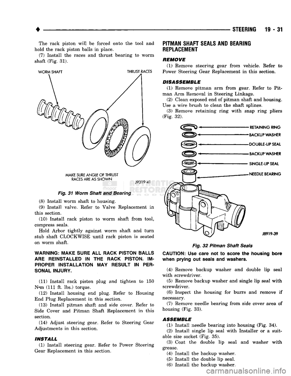
hold the rack piston balls in place. (7) Install the races and thrust bearing to worm
shaft (Fig. 31).
WORM
SHAFT
THRUST
RACES
MAKE
SURE
ANGLE
OF
THRUST
RACES
ARE AS
SHOWN
J9319-41
Fig.
31 Worm Shaft and Bearing
(8) Install worm shaft to housing. (9) Install valve. Refer to Valve Replacement in
this section.
(10) Install rack piston to worm shaft from tool,
compress seals. Hold Arbor tightly against worm shaft and turn
stub shaft CLOCKWISE until rack piston is seated
on worm shaft.
WARNING: MAKE
SURE
ALL
RACK PISTON BALLS
ARE
REINSTALLED
IN THE
RACK PISTON.
IM
PROPER
INSTALLATION
MAY
RESULT
IN
PER
SONAL INJURY.
(11) Install rack piston plug and tighten to 150
N»m (111 ft. lbs.) torque. (12) Install housing end plug. Refer to Housing
End Plug Replacement in this section. (13) Install pitman shaft and side cover. Refer to
Side Cover and Pitman Shaft Replacement in this
section.
(14) Adjust steering gear. Refer to Steering Gear
Adjustments in this section.
PITMAN
SHAFT
SEALS AND
BEARING
REPLACEMENT
REMOVE (1) Remove steering gear from vehicle. Refer to
Power Steering Gear Replacement in this section.
DISASSEMBLE
(1) Remove pitman arm from gear. Refer to Pit
man Arm Removal in Steering Linkage.
(2) Clean exposed end of pitman shaft and housing.
Use a wire brush to clean the shaft splines. (3) Remove retaining ring with snap ring pliers
(Fig. 32).
RETAINING
RING
BACKUP WASHER
DOUBLE-UP SEAL
BACKUP WASHER
SINGLE-LIP SEAL
NEEDLE
BEARING
J8919-39
Fig.
32 Pitman Shaft
Seals
CAUTION:
Use
care
not to
score
the
housing
bore
when
prying
out
seals
and
washers.
(4) Remove backup washer and double lip seal
with screwdriver.
(5) Remove backup washer and single lip seal with
screwdriver. (6) Inspect the housing for burrs and remove if
necessary.
(7) Remove needle bearing from side cover area of
housing (Fig. 33).
ASSEMBLE
(1) Install needle bearing into housing (Fig. 34).
(2) Install single lip seal with Installer or a suit
able size socket (Fig. 35).
(3) Coat the double lip seal and washer with
grease. (4) Install the backup washer. (5) Install the double lip seal.
(6) Install the backup washer.
INSTALL
(1) Install steering gear. Refer to Power Steering
Gear Replacement in this section.
Page 999 of 1502
19
- 38
STEERING
KEY-IN SWITCH
&
MULTI FUNCTION
SWITCH CONTROL J918J-2
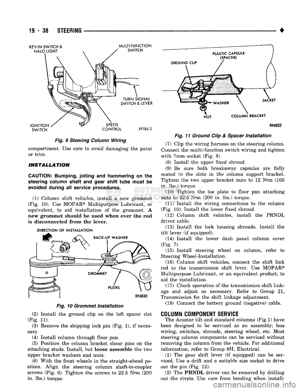
Fig.
9 Steering
Column
Wiring compartment. Use care to avoid damaging the paint
or trim.
INSTALLATION
CAUTION:
Bumping,
jolting and hammering on the
steering
column
shaft
and
gear
shift tube
must
be
avoided
during all service
procedures.
(1) Column shift vehicles, install a new grommet
(Fig. 10). Use MOPAR® Multipurpose Lubricant, or
equivalent, to aid installation of the grommet. A
new grommet should be used when ever the rod
is disconnected from the lever.
DIRECTION
OF
INSTALLATION
RN830
Fig.
10
Grommet
Installation
(2) Install the ground clip on the left spacer slot
(Fig. 11). (3) Remove the shipping lock pin (Fig. 1), if neces
sary. (4) Install column through floor pan.
(5) Position the column bracket shear pins on the
attaching studs. Install, but loose assemble the two
upper bracket washers and nuts. (6) With the front wheels in the straight-ahead po
sition. Align the steering column shaft-to-coupler
screws (Fig. 6). Tighten the screws to 22.5 N*m (200
in. lbs.) torque. RN832
Fig.
11
Ground
Clip &
Spacer
Installation
(7) Clip the wiring harness on the steering column.
Connect the multi-function switch wiring and tighten
with 7mm socket (Fig. 8).
(8) Install the upper fixed shroud.
(9) Be sure both breakaway capsules are fully
seated in the slots in the column support bracket.
Tighten the two upper bracket nuts to 12 N-m (105
in. lbs.) torque.
(10) Tighten the toe plate to floor pan attaching
nuts to 22.5 N-m (200 in. lbs.) torque.
(11) Install the wiring connections to the column
(Fig. 10). Install the lower fixed shroud. (12) Column shift vehicles, install the PRNDL
driver cable. (13) Install the lock housing shrouds. Install the
tilt lever (if equipped). (14) Install the lower dash panel column cover
(Fig. 7).
(15) Install steering wheel on column, refer to
Steering Wheel-Installation.
(16) Column shift vehicles, connect the shift link
rod to the transmission shift lever. Use MOPAR®
Multipurpose Lubricant, or an equivalent product, to
aid the installation. (17) Check operation of the transmission shift link
age and adjust as necessary. Refer to Group 21,
Transmission for the shift linkage adjustment.
(18) Connect the battery ground (negative) cable.
COLUMN
COMPONENT
SERVICE
The Acustar tilt and standard columns (Fig.l) have
been designed to be serviced as an assembly; less
wiring, switches, shrouds, steering wheel, etc. Most steering column components can be serviced without
removing the column from the vehicle. For additional
information, refer to Group 8H, Electrical. (1) The gear shift lever (if equipped) can be ser
viced. Use a drift and a suitable size socket to drive out the pin (Fig. 12). (2) The PRNDL driver can be removed by drilling
out the rivets. Use care from bending when install-