1993 DODGE TRUCK diag code
[x] Cancel search: diag codePage 130 of 1502
•
REAR
SUSPENSION
AND
AXLE
3 - 1
CONTENTS
page
8
3/8 and 9 1/4
AXLE
11
GENERAL
INFORMATION
1
MODEL
60 and 70
AXLES
29
POWER-LOK DIFFERENTIAL
55
REAR
SUSPENSION—2WD
and
4WD VEHICLES
3
page
SERVICE
DIAGNOSIS
6
SPECIFICATIONS
27
SURE-GRIP
DIFFERENTIAL SERVICE
28
TORQUE SPECIFICATIONS
59
TRAC-LOK DIFFERENTIAL
51
GENERAL INFORMATION
SUSPENSION
Ram Truck rear suspensions
are
comprised
of;
• Drive axle
• Leaf springs
• Dual-action shock absorbers
• Jounce bumpers (used
to
limit
the
travel
of the
suspension) All
Ram
Truck
and
Ramcharger vehicles
are
equipped with leaf-type rear springs.
The
springs
have
a
one-piece, rubber bushing pressed into their main leaf front
eye.
Model
150 and
Ramcharger
ve
hicles
are
equipped with
a
fixed-rate type leaf spring. Progressive-rate type rear leaf springs
are
standard equipment
for all
Model
250 and 350
vehicles.
AXLES
The
8 3/8, 9
1/4-Inch
,
Model
60 and 70
axle hous
ings consist
of a
cast iron center section. They also
have
two
steel axle shaft tubes that
are
pressed into and welded
to the
differential housing. The removable, stamped steel cover provides
a
means
for
inspection
and
service without removing
the complete axle from
the
vehicle. Both axle types
are
equipped with
a
remote vent
fitting. A small, stamped metal axle gear ratio identifica
tion
tag is
attached
to the
housing cover. The rear wheel anti-lock (RWAL) brake speed sen
sor
is
attached
to the top,
forward exterior
of the dif
ferential housing.
A
seal
is
located between
the
sensor
and the
wire harness connector.
The
seal
must
be
in-plaee when
the
wire connector
is
connected
to the
sensor.
The
RWAL brake exciter
ring
is
press-fitted onto
the
differential case against
the flange. A rear axle equipped with
a
Sure-Grip differential
is optionally available
for
both
Ram
Truck
and
Ram
charger vehicles.
The
Sure-Grip
has a
two-piece case
that
is
interchangeable with
a
standard differential.
A limited-slip differential
is
optional
on
Model
60,
and
70
rear axles.
The
Model
60
uses
the
Trac-Lok
differential
and the
Model
70
uses
the
Power-Lok
dif
ferential.
The
Trac-Lok differential uses
a
one-piece case while
the
Power-Lok differential uses
a two-
piece case. Both
use the
same internal components
as
a standard differential, plus
two
clutch disc packs.
IDENTIFICATION The axle differential covers
can be
used
for
identi
fication (Fig.
1, 2, 3).
Model
60
axle
has the
assembly part number
and
gear ratio listed
on a tag. The tag is
attached
to the
left side
of the
housing cover
(Fig. 3).
Build date
identification codes
on
axles
are
stamped
on the
axle
shaft tube cover side.
LUBRICANTS
Multi-purpose, hypoid gear lubricant should
be
used
for
rear axles with either
a
standard
or a
Sure- Grip differential.
The
lubricant should have MIL-L-
2105-B
and by API GL 5
quality specifications.
MOPAR Hypoid Gear Lubricant conforms
to
both
of
these specifications.
In
addition,
4
ounces
of
Hypoid Additive must
be
included with
a
re-fill
for
Sure-Grip differentials.
If
the
rear axle
is
submerged
in
water,
the lu
bricant must
be
replaced immediately. Avoid axle failure resulting from water contamination
of
the
lubricant.
REAR
SUSPENSION
AND
AXLE
Page 246 of 1502
•
BRAKES
5 - 59
REAR
WHEEL
ANTILOCK
(RWAL) BRAKES
page
Antilock
Component Service
63
Antilock
Service Diagnosis
62
Checking
Speed
Sensor
Air
Gap .............
64
Clearing
A
Fault
Code .....................
63
Electronic
Control
Module Replacement
........
64
Fault Code Capacity
62
Fault Code
Identification
62
page
General
Information
59
Hydraulic Valve Replacement
63
Speed
Sensor
Replacement
................
64
System
Components
......................
59
System
Fault
Codes
......................
62
System
Operation
61
GENERAL
INFORMATION
A rear wheel antilock brake system
is
standard
equipment
on all AD
models.
It is an
electronically operated system designed
to
retard rear wheel lockup
during periods
of
high wheel slip
and
deceleration.
Retarding lockup
is
accomplished
by
modulating
fluid pressure
to the
rear brake units. Rear brake fluid apply pressure
is
modulated
ac
cording
to
wheel speed, degree
of
wheel slip
and
rate
of deceleration.
A
sensor located
in the
rear axle
housing converts differential rotating speed into elec
tronic signals.
The
signals
are
transmitted
to the
electronic brake control module
for
processing.
The
control unit determines rate
of
deceleration
and
wheel slip from these signals.
SYSTEM
COMPONENTS
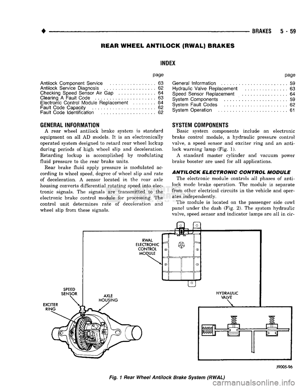
Basic system components include
an
electronic
brake control module,
a
hydraulic pressure control
valve,
a
speed sensor
and
exciter ring
and an
anti- lock warning lamp (Fig.
1).
A standard master cylinder
and
vacuum power
brake booster
are
used
for all
applications.
ANTILOCK ELECTRONIC CONTROL MODULE
The electronic module controls
all
phases
of
anti-
lock mode brake operation.
The
module
is
separate
from other electrical circuits
in the
vehicle
and
oper ates independently.
The module
is
located
on the
passenger side cowl
panel under
the
dash
(Fig.
2).
The
system hydraulic
valve, speed sensor
and
indicator lamps
are all in cir-
SPEED
SENSOR
EXCITER RING j3l
a
RWAL
ELECTRONIC
CONTROL MODULE AXLE
HOUSING HYDRAULIC
VALVE
J9005-96
Fig.
1
Rear
Wheel
Antilock
Brake
System
(RWAL)
Page 249 of 1502
i - 62
BRAKES
•
Isolation/Dump
Valve Cycle Times
Activation (opening/closing) of the isolation and
dump valves is continuous during antilock operation.
The valves cycle rapidly in response to speed sensor inputs and control module signal commands. Cycle
times are measured in milliseconds.
As the demand for antilock mode brake operation
is decreased, the module deactivates the hydraulic
valve components to restore normal brake operation.
ANTILOCK
SERVICE
DIAGNOSIS
GENERAL INFORMATION An antilock system malfunction will be indicated
by illumination of the amber antilock warning lamp.
The red brake warning lamp may also illuminate.
If a problem occurs, system diagnosis should begin
with a fluid level check followed by a visual exami
nation of the system electrical and hydraulic connec
tions.
If obvious defects (low fluid, leaks, loose connections, etc.) are not evident, road test the vehi
cle.
A road test should help determine if a malfunc
tion is actually related to an antilock component.
During the road test, note if other conditions are
evident such as a low pedal, pull, grab, or similar condition. Remember that brake malfunctions such as low fluid, system leaks, parking brakes partially
applied, will also affect the antilock system. The idea
is to determine if a malfunction is actually related to
an anti-lock component.
If a road test does reveal a problem, repeat the
road test with the owner driving. Make sure the owner is not riding the brake pedal, or has forgotten
to release the parking brakes. Either situation will
generate a fault and cause the antilock light to illu
minate.
SYSTEM FAULT
CODES
The antilock control module generates flash codes
to help identify the cause of an antilock system fault. Two different control modules are used with the
1992/1993 RWAL system. A type I module is used in
some early production models. All remaining produc
tion models are equipped with a type II module. The type I and II modules are identified by the way
fault codes 9 and 11 are processed. If the vehicle has a type I module, codes 9 and 11 are not erased when
the ignition switch is turned to Off position. If the vehicle has a type II module, codes 9 and 11 are
erased when the switch is turned to Off.
FAULT CODES WITH TYPE I CONTROL
MODULE
The microprocessor in the electronic control module
has a memory and a self test feature. The self test
feature is activated whenever the ignition switch is
turned to Accessory or Run position. If a system fault is detected, the control module il
luminates the antilock light and stores the fault code
in memory. Fault codes are retained in memory even after turning the ignition switch to Off position.
FAULT CODES WITH TYPE II CONTROL
MODULE The microprocessor in the electronic control module
has a memory and a self test feature. The self test
feature is activated whenever the ignition switch is
turned to Accessory or Run position.
If a system fault is detected, the control module
will illuminate the antilock indicator lamp and store
fault codes 1 through 8, 10 and 12 through 15 in the
microprocessor memory. When one of these fault
codes is generated, the control module will retain the code after the ignition switch is turned to the Off po
sition.
When fault code 9 is generated, the code only re
mains in microprocessor memory while the ignition switch is in Run position. Turning the ignition
switch to Off position erases fault code 9. However, if
the problem still exists when the switch is turned
back to Run position, code 9 will reappear in memory after 20 seconds and the antilock light will illumi
nate once again.
When fault code 11 is generated, the antilock light
will illuminate when vehicle speed exceeds approxi mately 60.35 km/h (37.5 mph). Code 11 only remains in memory while the ignition switch is in the Run
position and the fault is present.
When the cause of a fault code 11 is corrected, the
antilock light goes off. Code 11 is erased when the ig
nition switch is turned to Off position. However, if
the problem cause still exists when the ignition switch is turned to Run position, code 11 will reap
pear when vehicle speed exceeds approximately 60.35 km/h (37.5 mph).
FAULT
CODE
CAPACITY
The microprocessor memory will store and display
only one fault code at a time. The stored code can be
displayed by grounding the RWAL diagnostic connec
tor.
FAULT
CODE
IDENTIFICATION
To determine what the fault code is, momentarily
ground the RWAL diagnostic connector and count
the number of times the amber antilock lamp flashes. Fault codes and typical malfunctions are outlined in Figure 8. Note that when a fault code is gen
erated, the red brake warning lamp will also
illuminate. The initial flash will be a long flash followed by a
number of short flashes. The long flash indicates the
beginning of the fault number sequence and the short flashes are a continuation of that sequence.
Page 276 of 1502
•
COOLING
SYSTEM
7 - 6 COOLING SYSTEM DIAGNOSIS (EXCEPT DIESEL)
CONDITION
AND
CHICK
OPTIONAL
M°¥
GAUGE
READS
LOW
(!) Verify
gauge
reading. Is a low temperature indicated?
(2) Is code 17 recorded in On Board
Diagnostics
memory?
(3) Is the
gauge
reading in the cold
range?
(4) Low coolant level during cold ambient temperatures
(accompanied
with poor heater performance).
(5) Coolant level is correct.
GAUGE
HEADING
HIGH.
NO
PRESSURE
BLOW
OFF
FROM
RADIATOR
PRESSURE
CAP
OR
STEAM
FROM
COOLANT
RESERVE
TANK.
(1) Verify
gauge
reading. Is a high temperature reading indicated?
(2)
Gauge
reading at
"H"
without
signs
of boiling.
(3) Low coolant level in radiator and coolant reserve tank.
(4) Coolant level in radiator is low. But not low in coolant reserve tank.
(5) Test coolant
freeze
point.
(6) Ensure proper coolant flow.
DIAGNOSIS
30° TO 40°
GAUGE
TRAVEL
IS
NORMAL
Normal
Gauge
Travel
(1) Inspect temperature
gauge
sending
unit. Refer to Group 8, Electrical. Repair or replace sending unit as necessary.
(2) If code 17 is recorded, replace the thermostat. If not, the thermostat is not the
cause
of the low
gauge
reading.
(3) Inspect for
disconnected
sending
unit electrical connector or incorrect
sending
unit. Ensure that
gauge
sending
unit is installed
and
not an indicator light switch.
(4)
WARNING:
DO NOT
REMOVE
THE
RADIATOR
CAP
OF A
HOT,
PRESSURIZED
ENGINE.
SERIOUS
INJURY
CAN
RESULT
FROM
SCALDING
COOLANT.
Inspect
coolant level in the coolant reserve tank and radiator.
Inspect
system
for leaks.
(5) Inspect heater door
controls.
Refer to Group 24, Heating and
Air
Conditioning.
TO
TOP
AMBIENT
High
Gauge
Reading
— Hot Weather — Heavy Load
(1) Compare
gauge
reading to
High
Gauge
Reading Illustration
above.
(2) Inspect for grounded
gauge,
sending
unit or circuit. Refer to
Group
8, Electrical.
(3) a — Pill to full.
b
— Inspect for leaks in
system
and repair as
necessary,
c
—
Ensure
radiator pressure cap was shut tight. Verify
proper
operation of the radiator cap upper and lower
seals.
(4) a —
Fill
to full,
b
— Inspect for leaks in the
system
and repair as
necessary,
c
— Inspect for leaks in the coolant reserve tank to radiator
hose.
d
— Verify proper operation of the radiator cap upper and lower
seals.
(5) a — Adjust coolant solution to
50/50
mixture of anti-freeze and water. Refer to Coolant in this
group,
b
— If a reading is not recorded or below
—
50, the mixture is
too
rich. Clean
system
and
fill
with a
50/50
mixture of
anti-freeze and water. Refer to Coolant in this
group.
(6) a •— With the thermostat open and a slight amount of coolant
removed,
inspect for coolant flow through the radiator at
the
filler
neck opening,
b
— Determine reason for lack of coolant flow and repair as
necessary.
J9007-69
Page 279 of 1502
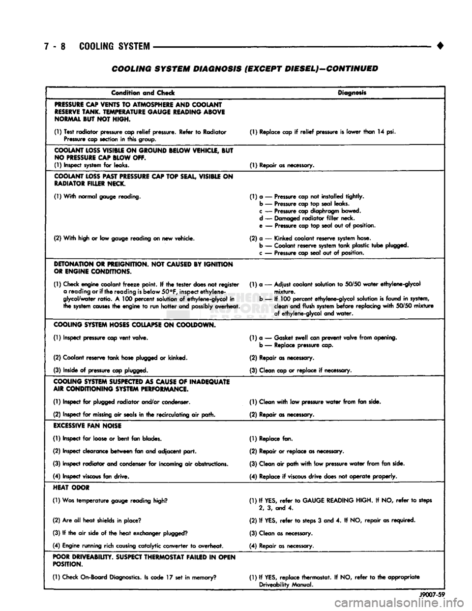
7 - 8
COOLING
SYSTEM
COOLING SYSTEM DIAGNOSIS (EXCEPT DIESEL)—CONTINUED
Condition and Check
Diagnosis
PRESSURE
CAP
VENTS
TO
ATMOSPHERE
AND COOLANT
RESERVE
TANK.
TEMPERATURE
GAUGE
READING
ABOVE
NORMAL
BUT NOT HIGH.
(1) Test radiator pressure cap
relief
pressure. Refer to Radiator Pressure cap section in this group. (1) Replace cap if
relief
pressure is lower than 14 psi.
COOLANT
LOSS
VISIBLE
ON
GROUND
BELOW
VEHICLE,
BUT
NO
PRESSURE
CAP
BLOW
OFF.
(1) Inspect
system
for leaks. (1) Repair as necessary.
COOLANT
LOSS
PAST
PRESSURE
CAP
TOP
SEAL,
VISIBLE
ON
RADIATOR
FILLER
NECK.
(1) With normal gauge reading. (1) a — Pressure cap not installed tightly.
b — Pressure cap top seal leaks.
c
— Pressure cap diaphragm bowed.
d — Damaged radiator
filler
neck.
e — Pressure cap top seal out of position.
(2) With high or low gauge reading on new vehicle. (2) a — Kinked coolant reserve
system
hose.
b — Coolant reserve
system
tank
plastic
tube
plugged,
c
— Pressure cap seal out of position.
DETONATION
OR
PREIGNITION.
NOT
CAUSED
BY IGNITION
OR
ENGINE
CONDITIONS.
(1) Check engine coolant
freeze
point. If the
tester
does
not register a reading or if
the
reading
is
below
50°F,
inspect
ethylene-
glycol/water
ratio.
A 100
percent
solution of ethylene-glycol in
the
system
causes
the engine to run
hotter
and
possibly
overheat. (1) a — Adjust coolant solution to
50/50
water
ethylene-glycol
mixture.
b — If 100
percent
ethylene-glycol solution
is
found in system, clean and flush
system
before
replacing
with
50/50
mixture
of ethylene-glycol and
water.
COOLING
SYSTEM
HOSES
COLLAPSE
ON
COOLDOWN.
(1) Inspect pressure cap
vent
valve. (1) a — Gasket swell can
prevent
valve from opening,
b — Replace pressure cap.
(2) Coolant reserve
tank
hose plugged or kinked. (2) Repair as necessary.
(3) Inside of pressure cap plugged. (3) Clean cap or replace if necessary.
COOLING
SYSTEM
SUSPECTED
AS
CAUSE
OF
INADEQUATE
AIR
CONDITIONING
SYSTEM
PERFORMANCE.
(1) Inspect for plugged radiator and/or condenser. (1) Clean
with
low pressure
water
from fan side.
(2) Inspect for
missing
air
seals
in the recirculating air path. (2) Repair as necessary.
EXCESSIVE
FAN
NOISE
(1) Inspect for loose or
bent
fan blades. (1) Replace fan.
(2) Inspect clearance
between
fan and adjacent
part.
(2) Repair or replace as necessary.
(3) Inspect radiator and condenser for incoming air obstructions. (3) Clean air path
with
low pressure
water
from fan side.
(4) Inspect
viscous
fan drive. (4) Replace if
viscous
drive
does not
operate
properly.
HEAT
ODOR
(1) Was
temperature
gauge reading
high?
(1) If
YES,
refer
to
GAUGE
READING
HIGH. If NO,
refer
to steps
2, 3, and 4.
(2) Are all
heat
shields in place? (2) If
YES,
refer
to
steps
3 and 4. If NO,
repair
as required.
(3) If the air side of the
heat
exchanger
plugged?
(3) Clean as necessary.
(4) Engine running rich
causing
catalytic converter to overheat. (4) Repair as necessary.
POOR
DRIVEABIUTY.
SUSPECT
THERMOSTAT
FAILED
IN
OPEN
POSITION.
(1) Check On-Board
Diagnostics.
Is code 17 set in memory? (1) If
YES,
replace thermostat. If NO,
refer
to the appropriate
Driveability Manual.
J9007-59
Page 280 of 1502
•
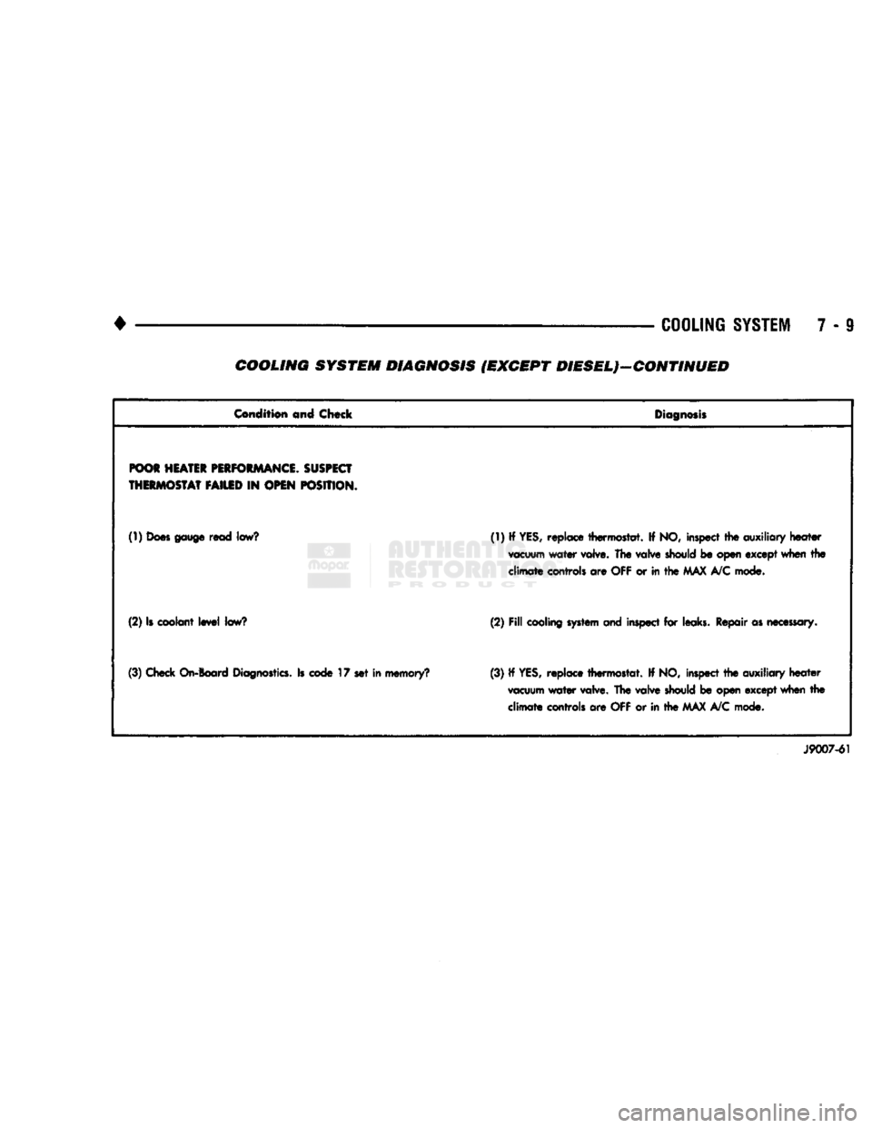
COOLING
SYSTEM
7 - 9 COOLING SYSTEM DIAGNOSIS (EXCEPT DIESEL)—CONTINUED
Condition
and Chock
Diagnosis
POOR
HEATER
PERFORMANCE.
SUSPECT
THERMOSTAT
FAILED
IN
OPEN
POSITION.
(1)
Does gauge
read
low?
(1) If YES, replace thermostat. If NO, inspect the
auxiliary
heater
vacuum
water valve. The
valve
should
be open except when the
climate
controls are
OFF
or in the
MAX
A/C mode.
(2) Is coolant level
low?
(2)
Fill
cooling system and
inspect for leaks. Repair as
necessary.
(3) Check
On-Board
Diagnostics.
Is
code
17 set in memory? (3) If
YES,
replace thermostat. If NO, inspect the auxiliary heater
vacuum
water valve. The valve
should
be open except when the climate controls are OFF or in the MAX A/C mode.
J9007-61
Page 294 of 1502
•
COOLING SYSTEM
7 - 23
•THERMOSTAT
MACHINED GROOVE
J9207-14
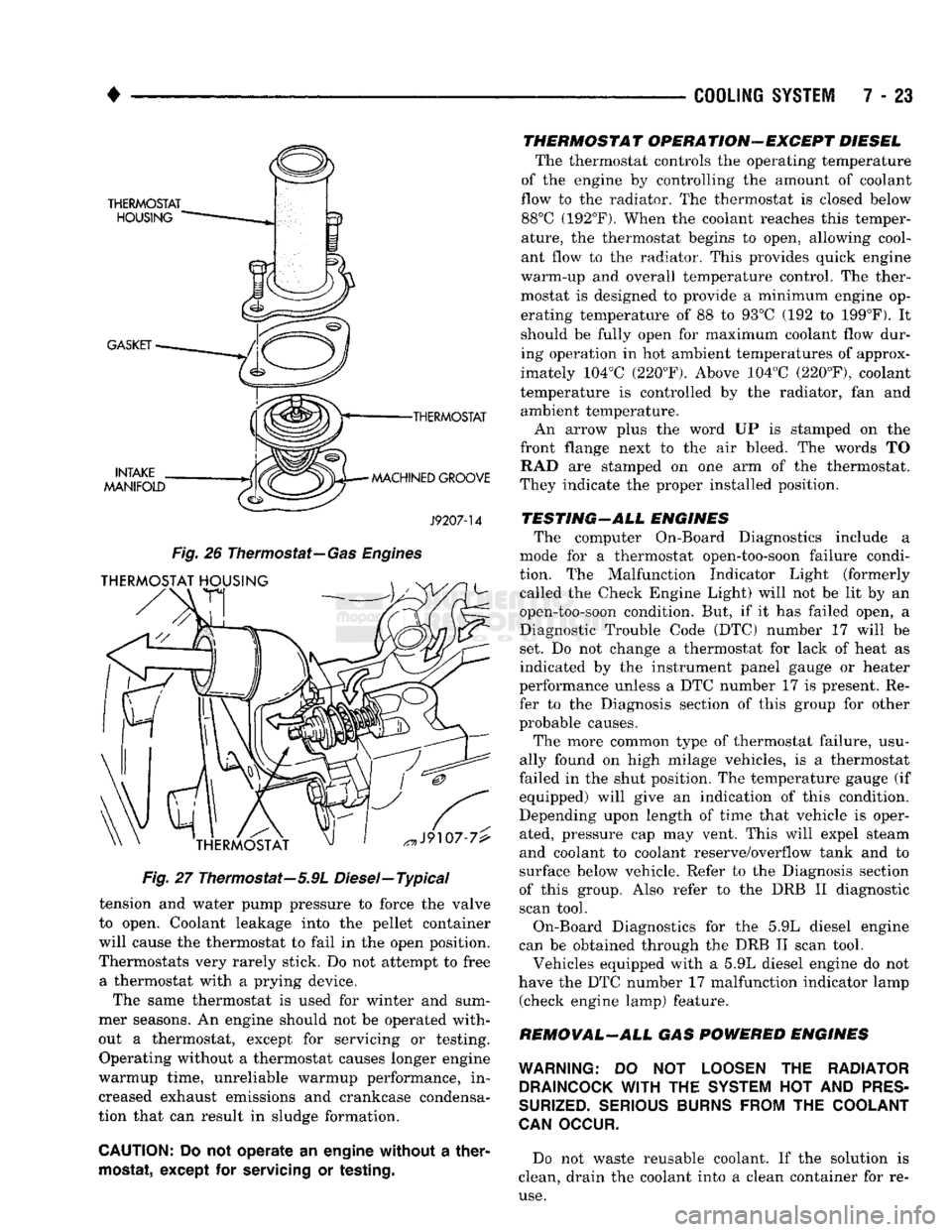
Fig.
26
Thermostat—
Gas Engines
Fig.
27 Thermostat—5.9L Diesel—Typical
tension and water pump pressure to force the valve
to open. Coolant leakage into the pellet container
will cause the thermostat to fail in the open position.
Thermostats very rarely stick. Do not attempt to free a thermostat with a prying device.
The same thermostat is used for winter and sum
mer seasons. An engine should not be operated with
out a thermostat, except for servicing or testing. Operating without a thermostat causes longer engine
warmup time, unreliable warmup performance, in
creased exhaust emissions and crankcase condensa
tion that can result in sludge formation.
CAUTION:
Do not operate an engine without a
ther
mostat,
except for
servicing
or
testing.
THERMOSTAT OPERATION-EXCEPT DIESEL
The thermostat controls the operating temperature
of the engine by controlling the amount of coolant
flow to the radiator. The thermostat is closed below 88°C (192°F). When the coolant reaches this temper
ature, the thermostat begins to open, allowing cool
ant flow to the radiator. This provides quick engine
warm-up and overall temperature control. The ther
mostat is designed to provide a minimum engine op erating temperature of 88 to 93°C (192 to 199°F). It
should be fully open for maximum coolant flow dur
ing operation in hot ambient temperatures of approx
imately 104°C (220°F). Above 104°C (220°F), coolant
temperature is controlled by the radiator, fan and ambient temperature.
An arrow plus the word UP is stamped on the
front flange next to the air bleed. The words TO RAD are stamped on one arm of the thermostat.
They indicate the proper installed position.
TESTING-ALL ENGINES The computer On-Board Diagnostics include a
mode for a thermostat open-too-soon failure condi
tion. The Malfunction Indicator Light (formerly called the Check Engine Light) will not be lit by an
open-too-soon condition. But, if it has failed open, a
Diagnostic Trouble Code (DTC) number 17 will be
set. Do not change a thermostat for lack of heat as
indicated by the instrument panel gauge or heater
performance unless a DTC number 17 is present. Re
fer to the Diagnosis section of this group for other
probable causes.
The more common type of thermostat failure, usu
ally found on high milage vehicles, is a thermostat
failed in the shut position. The temperature gauge (if equipped) will give an indication of this condition.
Depending upon length of time that vehicle is oper
ated, pressure cap may vent. This will expel steam
and coolant to coolant reserve/overflow tank and to
surface below vehicle. Refer to the Diagnosis section
of this group. Also refer to the DRB II diagnostic
scan tool.
On-Board Diagnostics for the 5.9L diesel engine
can be obtained through the DRB II scan tool.
Vehicles equipped with a 5.9L diesel engine do not
have the DTC number 17 malfunction indicator lamp (check engine lamp) feature.
REMOVAL-ALL GAS POWERED ENGINES
WARNING:
DO NOT
LOOSEN
THE
RADIATOR DRAINCOCK
WITH
THE
SYSTEM
HOT AND
PRES
SURIZED.
SERIOUS BURNS FROM
THE
COOLANT
CAN
OCCUR.
Do not waste reusable coolant. If the solution is
clean, drain the coolant into a clean container for re
use.
Page 329 of 1502
8A
- 8
ELECTRICAL
BATTERY
DIAGNOSTICS
CHART
STARTER
WONT
CRANK
BROKEN/CRACKED
F. C.
= 1
REPLACE
BATTERY* VISUAL
INSPECTION
CHECK
FOR OBVIOUS DAMAGE SUCH AS CRACKED OR
BROKEN
CASE
THAT
SHOWS
LOSS
OF ELECTROLYTE,
TERMINAL DAMAGE, LOOSE OR CORRODED
CONNECTIONS, CLEAN AND
TIGHTEN
CONNECTORS
STARTER
STILL
WONT
CRANK
PROCEED
TO STARTER TEST
PROCEDURES
ON VEHICLE IN THIS GROUP NO OBVIOUS DAMAGE
CHECK
TEST INDICATOR/OPEN CIRCUIT VOLTAGE
POSSIBLE
CAUSE—I0D-REFER
TO
IGNITION
OFF DRAW SECTION TEST INDICATOR/OPEN CIRCUIT VOLTAGE TEST
1.
TURN
HEADLAMPS ON FOR 15 SECONDS
2.
TURN
HEADLAMPS OFF FOR
5
MINUTES TO ALLOW BATTERY VOLTAGE TO STABILIZE
3. REMOVE NEGATIVE,
THEN
POSITIVE CABLE.
ELIMINATE
EXCESS
F. C.
= 3
IOD
NO
EXCESS
IOD FOUND
•CHARGE
BATTERY-REFER TO CHARGING BATTERY
CHARGE
ACCEPTED
GREEN
BALL SHOWING AND
OPEN CIRCUIT VOLTAGE
ABOVE
12.40
VOLTS**
WONT
ACCEPT CHARGE F.
C = 4
1.
NO
GREEN BALL SHOWING
2. OPEN CIRCUIT VOLTAGE BELOW
12.40
VOLTS. SEE CHARGING COMPLETELY
DISCHARGED
BATTERY YELLOW OR BRIGHT INDICATOR
F.
C.
= 2
DO NOT CHARGE, BOOST, OR
TEST, ELECTROLYTE BELOW INDICATOR. REPLACE BATTERY,
CHECK
CHARGING SYSTEM
T
STARTER
STILL
WONT
CRANK
PROCEED
TO STARTER TEST
PROCEDURES
ON VEHICLE
IN
THIS GROUP LOAD TEST
DISCHARGE
BATTERY AT
300
AMPERES
FOR
15
SECONDS.
ALLOW BATTERY
TO RECOVER FOR
15
SECONDS.
CONNECT VOLTMETER AND AMPERE LOAD EQUAL TO
1/2
THE COLD CRANKING AMPERE RATING OF THE BATTERY FOR 15
SECONDS.
OBSERVE VOLTAGE AT 15 SECONDS
WITH
LOAD ON.
NOTE: ESTIMATE TEMPERATURE
OF
BATTERY.
REFER
TO
LOAD TEST VOLTAGE CHART. VOLTAGE AT OR ABOVE
9.6 VOLTS AT ROOM (70 DEG. F) TEMP. VOLTAGE BELOW
9.6 VOLTS AT ROOM (70 DEG. F) TEMP.
PASSED
LOAD TEST
RETURN BATTERY TO USE FAILED LOAD TEST
F. C.
= 5
*
REPLACE
BATTERY LOAD TEST VOLTAGE CHARGE
ESTIMATED
ELECTROLYTE
TEMPERATURE
70°
60°
50°
40° 30°
20° 10° 0° (21°
C)& ABOVE
(16° C
(16°
C (4°
C
H°C
1-7°
C
(-12°C
(-18°C
MINIMUM
REQUIRED VOLTAGE UNDER
15 SEC. LOAD 9.6
9.5
9.4 9.3 9.1
8.9
8.7
8.5 VOLTMETER MUST BE ACCURATE
TO
1/10
VOLT
STARTER
ST8LL
WONT
CRANK
PROCEED
TO
STARTER TEST
PROCEDURES
ON
VEHICLE
IN
THIS GROUP
NOTES:
* AFTER CHARGING
OR
REPLACING
A
BATTERY,
CHECK
THE VEHICLE'S CHARGING SYSTEM,
AND
CLEAN
AND
TIGHTEN
BATTERY CONNECTORS (REFER
TO
APPLICABLE SECTIONS
OF
THIS
SERVICE
MANUAL). FAILURE CODE
(F.C)
CHART
FAILURE CODE (R
C)
NUMBER
CONDITION
1
2
3
4
5
BROKEN/CRACKED
YELLOW/BRIGHT INDICATOR
IGNITION
OFF DRAW
BATTERY
WON'T
ACCEPT CHARGE BATTERY FAILED LOAD TEST
** CHECKING OPEN CIRCUIT VOLTAGE
WILL
MONITOR ''GREEN BALL" INDICATION
FOR ALL
6
CELLS.
J938A-22