1993 DODGE TRUCK hood open
[x] Cancel search: hood openPage 8 of 1502
INTRODUCTION
PRIMARY SECONDARY
PAINT PAINT VINYL ROOF
CODE VEHICLE
ORDER-
NUMBER
PAINT- PI
PROCEDURE
(2)
(1)
XXX
)
XXXXX)
X
XXX xxxxxx
X)0C xxxx xxxx xxxx xxx XXX x xxxxxxxxxxxxxxxxx
TRANSMISSION
I
VEHICLE IDENTIFICATION CODE
J
NUMBER
MARKET
U-C-B-M
CODE 90IN-3
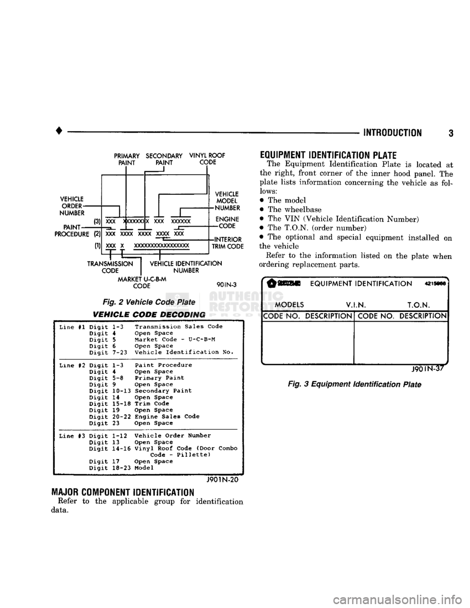
Fig. 2 Vehicle Code Plate
VEHICLE CODE DECODING
VEHICLE
MODEL
•NUMBER
ENGINE
-CODE
-INTERIOR TRIM CODE
Line #1 Digit
1-3 Transmission Sales Code
Digit 4 Open Space
Digit
5
Market Code - U-C-B-M
Digit 6 Open Space
Digit 7-23 Vehicle Identification No.
Line #2 Digit
1-3 Paint Procedure
Digit 4 Open Space
Digit 5-8 Primary Paint
Digit 9 Open Space
Digit 10-13 Secondary Paint
Digit 14 Open Space
Digit 15-18 Trim Code
Digit 19 Open Space
Digit
20-22
Engine Sales Code
Digit 23 Open Space
Line #3 Digit 1-12 Vehicle Order Number
Digit 13 Open Space
Digit 14-16 Vinyl Roof Code (Door Combo
Digit
Code - Pillette)
Digit 17 Open Space
Digit 18-23 Model
J901N-20 MAJOR COMPONENT IDENTIFICATION
Refer to the applicable group for identification
data.
EQUIPMENT IDENTIFICATION PLATE
The Equipment Identification Plate is located at
the right, front corner of the inner hood panel. The
plate lists information concerning the vehicle as fol
lows:
The model
The wheelbase
The VIN (Vehicle Identification Number)
The
T.O.N,
(order number)
The optional and special equipment installed on
the vehicle
Refer to the information listed on the plate when
ordering replacement parts.
r§Wll
EQUIPMENT
IDENTIFICATION
mmm
MODELS
V.I.N. T.O.N.
CODE
NO.
DESCRIPTION
CODE
NO.
DESCRIPTION
. ^
Fig.
3 Equipment
Identification
Plate
Page 39 of 1502
0
- 21
LUBRICATION
AND
MAINTENANCE
• SERVICE INFORMATION
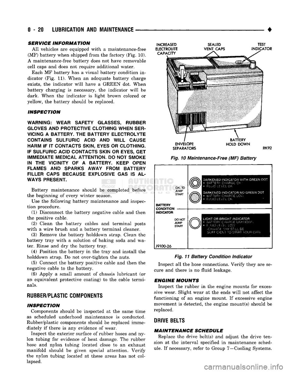
All vehicles are equipped with a maintenance-free
(MF) battery when shipped from the factory (Fig. 10).
A maintenance-free battery does not have removable
cell caps and does not require additional water. Each MF battery has a visual battery condition in
dicator (Fig. 11). When an adequate battery charge
exists,
the indicator will have a GREEN dot. When
battery charging is necessary, the indicator will be dark. When the indicator is light brown colored or
yellow, the battery should be replaced.
INSPECTION
WARNING; WEAR SAFETY
GLASSES,
RUBBER
GLOVES
AND
PROTECTIVE CLOTHING WHEN SER
VICING
A
BATTERY.
THE
BATTERY ELECTROLYTE CONTAINS SULFURIC ACID
AND
WILL CAUSE HARM
IF IT
CONTACTS SKIN, EYES
OR
CLOTHING.
IF SULFURIC ACID CONTACTS SKIN
OR
EYES,
GET
IMMEDIATE MEDICAL ATTENTION.
DO
NOT
SMOKE
IN
THE
VICINITY
OF A
BATTERY. KEEP OPEN
FLAMES
AND
SPARKS AWAY FROM BATTERY
FILLER CAPS BECAUSE EXPLOSIVE
GAS IS AL
WAYS
PRESENT.
Battery maintenance should be completed before
the beginning of every winter season.
Use the following battery maintenance and inspec
tion procedure. (1) Disconnect the battery negative cable and then
the positive cable.
(2) Clean the battery cables and terminal posts
with a wire brush and a battery terminal cleaner. (3) Remove the battery holddown strap. Clean the
battery tray with a solution of baking soda and wa
ter. Rinse and dry the battery tray.
(4) Position the battery in the tray and install the
holddown strap. Do not over-tighten the nuts.
(5) Connect the battery positive cable and then the
negative cable to the battery.
(6) Apply a small amount of chassis lubricant (or
an equivalent protective coating) to the cable termi
nals.
RUBBER/PLASTIC
COMPONENTS
INSPECTION Components should be inspected at the same time
as scheduled underhood maintenance is conducted.
Rubber/plastic components should be replaced imme diately if there is any evidence of wear. Inspect the exterior surface of rubber hoses and ny
lon tubing for evidence of heat damage. The rubber
hose and nylon tubing located close to an exhaust
manifold should be given special attention. Verify
the nylon tubing located at these areas has not col lapsed.
INCREASED
ELECTROUTE CAPACITY
SEALED
VENT
CAPS TEST
INDICATOR ENVELOPE
SEPARATORS
BATTERY
HOLD DOWN
RK92
Fig. 10 Maintenance-Free (MF)
Battery
O.K. TO
JUMP START
BATTERY
CONDITION
INDICATOR
J9100-26
DARKENED
INDICATOR
WITH
GREEN
DOT
•
BATTERY CHARGE
OK '
•
FLUID LEVEL
OK
DARKENED
INDICATOR
NO
GREEN
DOT
•
BATTERY CHARGE
LOW
FLUID LEVEL
OK
LIGHT
OR
BRIGHT INDICATOR
•
BATTERY CHARGE UNKNOWN
•
FLUID uEv'EL
LOW
(CHARGE
MAY
STILL
BE
SUFFICIENT
TO
START YOUR
CAR)
Fig. 11
Battery
Condition Indicator
Inspect all the hose connections. Verify they are se
cure and there is no fluid leakage.
ENGINE MOUNTS Inspect the rubber in the engine mounts for exces
sive wear. Slight wear at the ends will not affect the
functioning of an engine mount. If excessive engine
movement is detected, the engine mount(s) should be
replaced.
DRIVE
BELTS
MAINTENANCE SCHEDULE Replace the drive belt(s) and adjust the drive ten
sion at the interval specified in maintenance sched
ule.
If necessary, refer to Group 7—Cooling Systems.
Page 41 of 1502
0
- 22
LUBRICATION
AND
MAINTENANCE
DRIVETRAIN
INDEX
page
Axles
25
Clutch
and
Brake Pedal
Bushings
............ 22
Clutch Master Cylinder
22
Drive Shafts
26
page
Front Axle U-Joint
and
Pivot Bearings
......... 26
Transfer
Case
(4WD
Vehicles)
. . ........ 24
Transmissions
. 22
CLUTCH
AND
BRAKE PEDAL
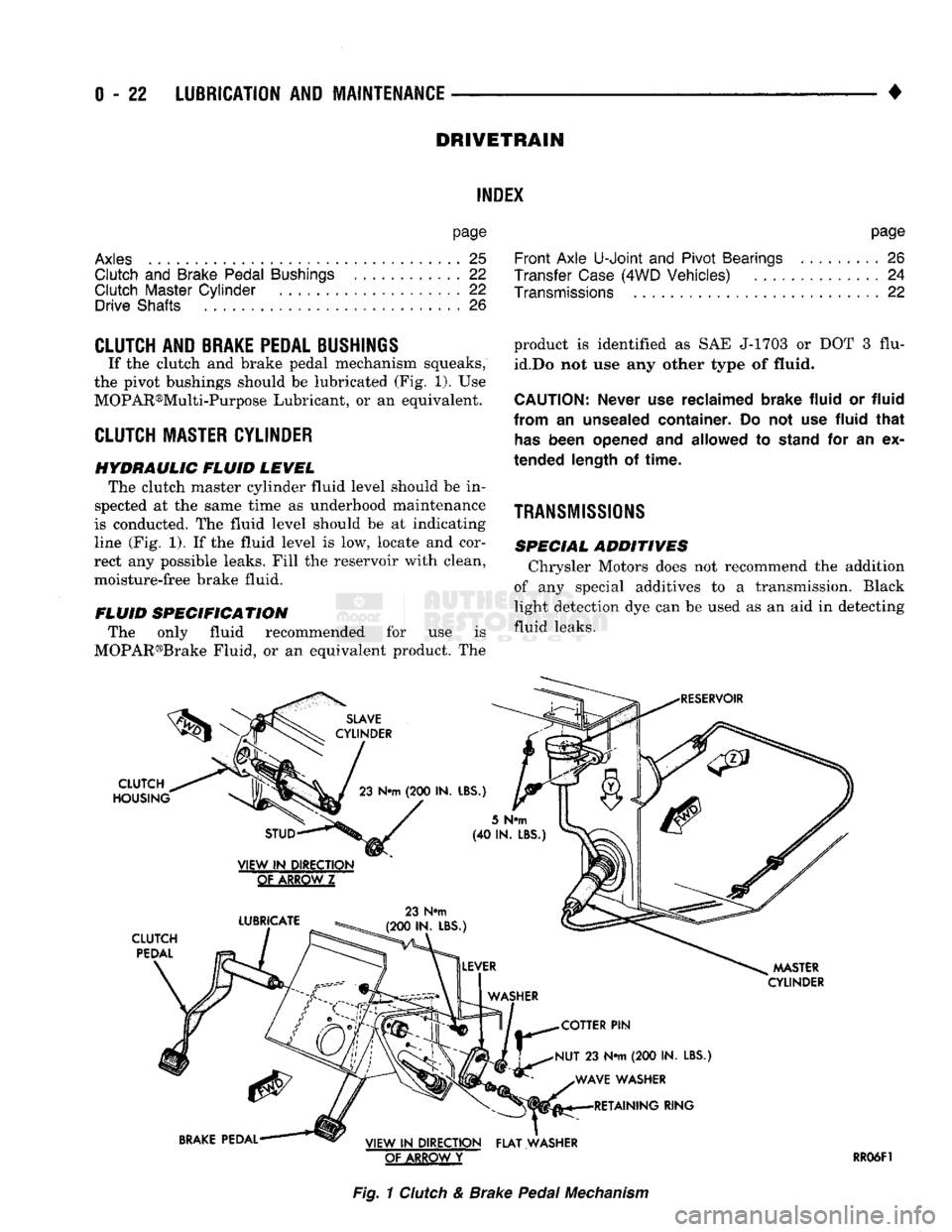
If the clutch and brake pedal mechanism squeaks,
the pivot bushings should be lubricated (Fig. 1). Use
MOPAR®Multi-Purpose Lubricant, or an equivalent.
CLUTCH
MASTER CYLINDER
HYDRAULIC FLUID LEVEL The clutch master cylinder fluid level should be in
spected at the same time as underhood maintenance
is conducted. The fluid level should be at indicating
line (Fig. 1). If the fluid level is low, locate and cor
rect any possible leaks. Fill the reservoir with clean,
moisture-free brake fluid.
FLUID SPECIFICATION The only fluid recommended for use is
MOPAR®Brake Fluid, or an equivalent product. The
SLAVE
CYLINDER
CLUTCH
HOUSING
23
N«m
(200 IN.
LBS.)
product is identified as SAE J-1703 or DOT 3 flu
id.Do not use any other type of
fluid.
CAUTION:
Never
use
reclaimed brake fluid
or
fluid
from
an
unsealed container.
Do not use
fluid that
has
been opened
and
allowed
to
stand
for an ex
tended length
of
time.
TRANSMISSIONS
SPECIAL ADDITIVES Chrysler Motors does not recommend the addition
of any special additives to a transmission. Black
light detection dye can be used as an aid in detecting
fluid leaks.
RESERVOIR
STUD
VIEW
IN
DIRECTION
GtAKBQWZ
LUBRICATE
CLUTCH
PEDAL
23 N#m
(200 IN. LBS.)
5
N«m
(40 IN.
LBS
MASTER
CYLINDER
COTTER
PIN
NUT
23 N*m (200 IN.
LBS.) WAVE WASHER RETAINING RING
BRAKE
PEDAL VIEW
IN
DIRECTION FLAT WASHER
OF ARROW
Y
RR06F1
Fig.
1
Clutch
& Brake
Pedal
Mechanism
Page 323 of 1502

8A
- 2
ELECTRICAL
•
MALFUNCTION
INDICATOR
LAMP
DIAGNOSTIC SCAN
TOOL
POWERTRAIN CONTROL
MODULE
GENERATOR
BATTERY
J938A-23
Fig.
2
Charging
System
Components—Typical
BATTERY TEST
PROCEDURES
INDEX
page
Battery
Charging
6
Battery
Load Test
5
Battery
Open
Circuit
Voltage Test
.............
4
Causes
of
Battery
Discharging
3
GENERAL
INFORMATION
The battery stores, stabilizes,
and
produces electri
cal current.
A
battery must
be
able
to
accept
a
charge
and
produce high-amperage current over
an
extended period.
A
chemical reaction takes place
be
tween sulfuric acid solution (electrolyte)
and
lead + /-
plates
in
each cell
of the
battery.
As the
battery discharges,
the
plates collect acid from
the
electro
lyte.
When
the
charging system charges
the
battery,
water
is
converted
to
sulfuric acid
in the
battery.
The
amount
of
acid (specific gravity)
in the
electrolyte
can
be
measured with
a
hydrometer.
A
factory
in
stalled battery
has a
built-in test indicator
to
help
determine state-of-charge.
The
factory installed bat
tery
is
also nonrefillable, water
can not be
added.
The battery
is
vented
to
release gases that
are cre-
page
General
Information
2
Ignition
Off
Draw (IOD)
4
State
of
Charge Test Using Test
Indicator
.......
3
Test
Indicator
3
ated when
the
battery
is
being charged.
The
battery
top,
posts,
and
terminals should
be
cleaned when other underhood maintenance
is
performed (Fig.
3).
WARNING:
DO
NOT
ATTEMPT
TO
ASSIST BOOST, CHARGE,
OR
TEST BATTERY WHEN ELECTROLYTE LEVEL IS BELOW THE TOP
OF
THE PLATES
(YELLOW
OR
BRIGHT COLOR
IS
VISIBLE). PER
SONAL
INJURY
MAY
OCCUR.
When
the
electrolyte level
is
below
the top of the
plates (yellow
or
bright indicator),
the
battery must
be replaced.
The
battery must
be
completely charged (green indicator)
and the top,
posts,
and
terminals
should
be
properly cleaned before diagnostic proce
dures
are
performed. Refer
to
Group
8B -
Battery/ Starter Service,
for
additional information.
Page 325 of 1502
8A
- 4
ELECTRICAL
•
IGNITION
OFF
DRAW
(IOD)
Ignition off draw refers to power being drained
from the battery with the ignition turned off. A nor
mal vehicle electrical system will draw from 5 to 20
milliamps. A vehicle that has not been operated for
an extended period of time (approximately 20 days)
may discharge the battery to an inadequate level.
Battery drain should not exceed approximately 20
MA (20 milliamps = 0.020 amps). The 20 MA are needed to supply PCM memory,
digital clock memory, and ETR (electronically tuned
radio) memory. Excessive battery drain is caused by items left
turned on, internally shorted generator, or intermit
tent short in wiring.
If the IOD is excessive (over 20 milliamperes), the
defect must be found and corrected before replacing a
battery. In most cases the battery can be charged and returned to service.
TEST PROCEDURE Testing for higher amperage IOD must be per
formed first to prevent damage to most milliamp
meters.
Verify that all electrical accessories are OFF. Turn
off all lights, remove ignition key, and close all
doors.
If the vehicle is equipped with electronic acces
sories (illuminated entry, high line radio), allow the
systems to automatically shut off (time out), up to 3
minutes.
(1) After determining that the underhood lamp is
operating properly then disconnect bulb. (2) Disconnect negative cable from battery.
(3) Connect a typical 12 volt test light (low watt
age bulb) between the negative cable clamp and the
battery negative terminal. The test light may light brightly for up to 3 min
utes or may not light at all (depending on the elec
trical equipment). The term brightly being used
throughout the following tests, implies the bright ness of the test light will be the same as if it were
connected across the battery.
The test light must be securely clamped to the neg
ative cable and battery terminal. If the test light be
comes disconnected during any of the IOD test, the electronic timer function will be activated and all
tests must be repeated.
(4) After 3 minutes, the test light should turn OFF
or be DIMLY lit (depending on the electrical equip
ment).
If the test light remains brightly lit do not
disconnect it. Remove each fuse or circuit breaker (refer to Group 8 - Wiring Diagrams) until test light
is either OFF or DIMLY lit. This will eliminate the
higher amperage draw.
If test light is still bright after disconnecting each
fuse and circuit breaker, disconnect the wiring har ness from the generator. Refer to Generator Testing
in this group. Do not disconnect the test light. After higher amperage IOD has been corrected, low
amperage IOD may be checked.
It is now safe to install milliamp meter to check for
low amperage IOD.
(5) With test light still connected, securely clamp
an ammeter between battery negative terminal and
negative battery cable.
If the test light or the milliamp meter circuit is
broken the various timer circuits will start. Do
not open any doors or turn on any electrical ac cessories with the test light disconnected or the
meter may be damaged.
(6) Disconnect test light. The current draw should
not exceed 0.020 amp. If it exceeds 20 milliamps iso
late each circuit by removing circuit breakers and
fuses.
The meter reading drops once the high current
problem is found. Repair this section of the circuit,
whether it is a wiring short or component failure.
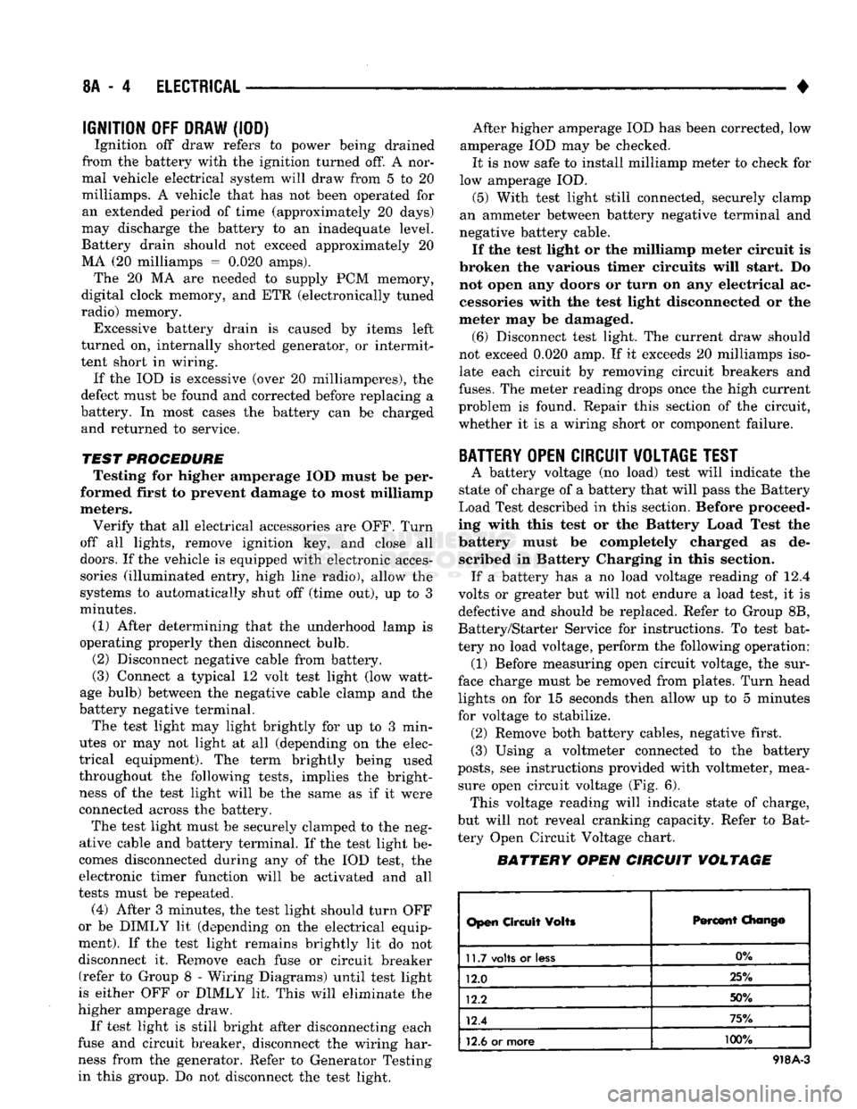
BATTERY
OPEN CIRCUIT VOLTAGE TEST
A battery voltage (no load) test will indicate the
state of charge of a battery that will pass the Battery
Load Test described in this section. Before proceed
ing with this test or the Battery Load Test the
battery must be completely charged as de scribed in Battery Charging in this section. If a battery has a no load voltage reading of 12.4
volts or greater but will not endure a load test, it is
defective and should be replaced. Refer to Group 8B,
Battery/Starter Service for instructions. To test bat
tery no load voltage, perform the following operation: (1) Before measuring open circuit voltage, the sur
face charge must be removed from plates. Turn head lights on for 15 seconds then allow up to 5 minutes
for voltage to stabilize. (2) Remove both battery cables, negative first.
(3) Using a voltmeter connected to the battery
posts,
see instructions provided with voltmeter, mea sure open circuit voltage (Fig. 6). This voltage reading will indicate state of charge,
but will not reveal cranking capacity. Refer to Bat
tery Open Circuit Voltage chart.
BATTERY OPEN CIRCUIT VOLTAGE
Open
Circuit
Volts
Percent
Chang©
11.7
volts
or
less
0%
12.0 25%
12.2 50%
12.4 75%
12.6
or more 100%
918A-3
Page 451 of 1502
8L
- 8
LAMPS
CONNECTOR
CUP
FRONT
LAMP
ASSEMBLY
LICENSE
PLATE
SCREW
LAMP
ASSEMBLY
LICENSE
PLATE
RR8LD24
Fig.
15
License
Plate
Lamps
-
Step
Bumper
TO
TAIL,
STOP,
TURN
SIG. AND
BACK
UP
LAMPS
LICENSE
PLATE
LICENSE
PLATE
LAMP
AND
LAMP
CONNECTOR
BRACKET
ASSEMBLY
J908L-74
Fig.
16
License
Plate
Lamp
Without Rear
Bumper
UNDERHOOD
LAMP
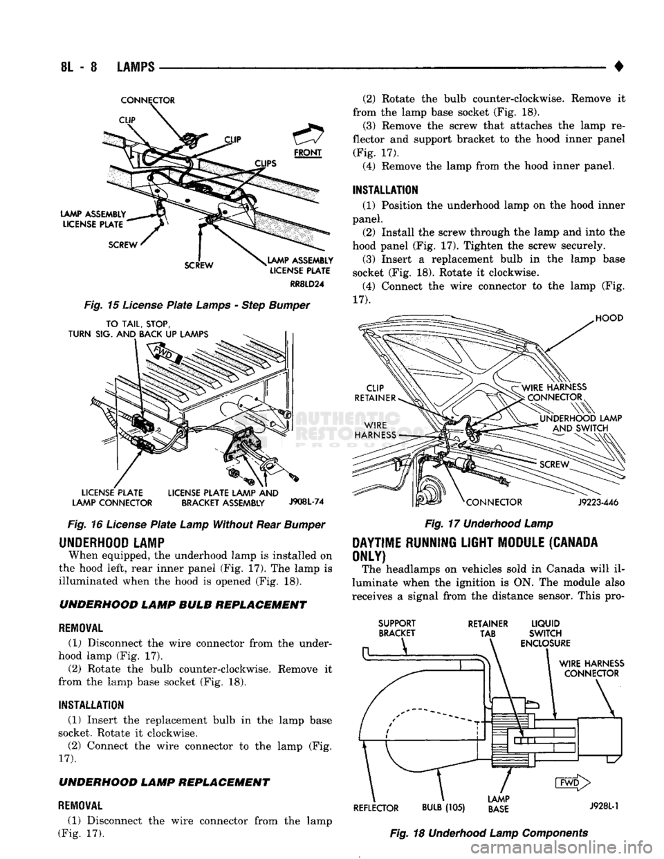
When equipped, the underhood lamp is installed on
the hood left, rear inner panel (Fig, 17). The lamp is
illuminated when the hood is opened (Fig. 18). UNDERHOOD LAMP BULB REPLACEMENT
REMOVAL
(1) Disconnect the wire connector from the under
hood lamp (Fig. 17).
(2) Rotate the bulb counter-clockwise. Remove it
from the lamp base socket (Fig. 18).
INSTALLATION
(1) Insert the replacement bulb in the lamp base
socket. Rotate it clockwise.
(2) Connect the wire connector to the lamp (Fig.
17).
UNDERHOOD LAMP REPLACEMENT
REMOVAL
(1) Disconnect the wire connector from the lamp
(Fig. 17). (2) Rotate the bulb counter-clockwise. Remove it
from the lamp base socket (Fig. 18). (3) Remove the screw that attaches the lamp re
flector and support bracket to the hood inner panel (Fig. 17).
(4) Remove the lamp from the hood inner panel.
INSTALLATION (1) Position the underhood lamp on the hood inner
panel. (2) Install the screw through the lamp and into the
hood panel (Fig. 17). Tighten the screw securely. (3) Insert a replacement bulb in the lamp base
socket (Fig. 18). Rotate it clockwise. (4) Connect the wire connector to the lamp (Fig.
17).
HOOD
J9223-446
Fig.
17
Underhood
Lamp
DAYTIME
RUNNING
LIGHT
MODULE
(CANADA
ONLY)
The headlamps on vehicles sold in Canada will il
luminate when the ignition is ON. The module also
receives a signal from the distance sensor. This pro-
SUPPORT
BRACKET RETAINER
LIQUID
TAB SWITCH
ENCLOSURE
WIRE
HARNESS
CONNECTOR
\
1
d1^—1—l
L/
CMD>
LAMP
REFLECTOR
BULB
(105)
BASE
J9281"1
Fig.
18
Underhood
Lamp
Components
Page 482 of 1502
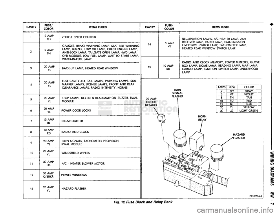
CAVITY
FUSE/
COLOR ITEMS FUSED
CAVITY
FUSE/
COLOR ITEMS FUSED
10
11
12
13 2 AMP
GY VEHICLE SPEED CONTROL
5 AMP TN
GAUGES,
BRAKE WARNING LAMP, SEAT BELT WARNING
LAMP, BUZZER, LOW OIL LAMP, CHECK ENGINE LAMP,
ANTI-LOCK LAMP, TAILGATE OPEN LAMP, 4WD LAMP, O/D MODULE, LOW FUEL LAMP,
WAIT
TO START LAMP
WATER-IN-FUEL LAMP 14
3 AMP
VT
20 AMP YL BACK-UP LAMP, HEATED REAR WINDOW
15 10 AMP
RD
ILLUMINATION
LAMPS, A/C HEATER LAMP, ASH
RECEIVER LAMP, RADIO LAMP, TRANSMISSION
OVERDRIVE SWITCH LAMP, TACHOMETER LAMP, HEATED REAR WINDOW SWITCH LAMP.
RADIO AND CLOCK MEMORY, POWER MIRRORS, GLOVE BOX LAMP, DOME LAMP, READING LAMP, MAP LAMP,
CARGO LAMP,
IGNITION
SWITCH LAMP, UNDERHOOD LAMP
20 AMP YL FUSE CAVITY #14,
TAIL
LAMPS, PARKING LAMPS, SIDE
AAARKER
LAMPS, LICENSE LAMPS, FRONT AND REAR CLEARANCE LAMPS, RADIO INTENSITY, HORNS
20 AMP YL STOP LAMPS, KEY-IN & HEADLAMP ON BUZZER, RWAL
MODULE 30 AMP
CIRCUIT
BREAKER
TURN
SIGNAL
FLASHER 20 AMP
YL POWER DOOR LOCKS
15 AMP
BL
CIGAR LIGHTER
10 AMP RD RADIO AND CLOCK
20 AMP YL
TURN
SIGNALS, TACHOMETER PROVISION,
RWAL MODULE
20 AMP YL WINDSHIELD WIPERS
30 AMP LG A/C - HEATER BLOWER MOTOR
30 AMP
C/BRKR
POWER WINDOWS
20 AMP YL HAZARD FLASHER
AMPS
FUSE
COLOR
2 GY GRAY
3 VT
VIOLET
5 TN
TAN
10 RD
RED
15
BL
BLUE
20 YL YELLOW
30 LG
LIGHT
GREEN HAZARD
FLASHER
J938W-94
Fig. 12 Fuse Block and
Relay
Bank
Page 514 of 1502
WIRING
DIAGRAMS
8W - 39
Wiring
Diagram
Name
Sheet
Number
Service Reminder Lamp .58
Side
Marker Lamp
Left
Front
43,45
Side
Marker Lamp Right
Front
. .44,46
Stop
Lamp-Left
Rear 79,81 Stop Lamp-Right Rear 80,81
Tachometer
.48
Tail
Lamp-Left
Rear .79,81
Tail
Lamp-Right Rear 80,81
Turn
Signal
Indicator
Lamps .79,80,81
Turn
Signal
Lamp-Left
Front
43,45
Turn
Signal Lamp-Right
Front
44,46
Turn
Signal
Lamp-Left
Rear .79,81
Turn
Signal Lamp-Right Rear 80,81
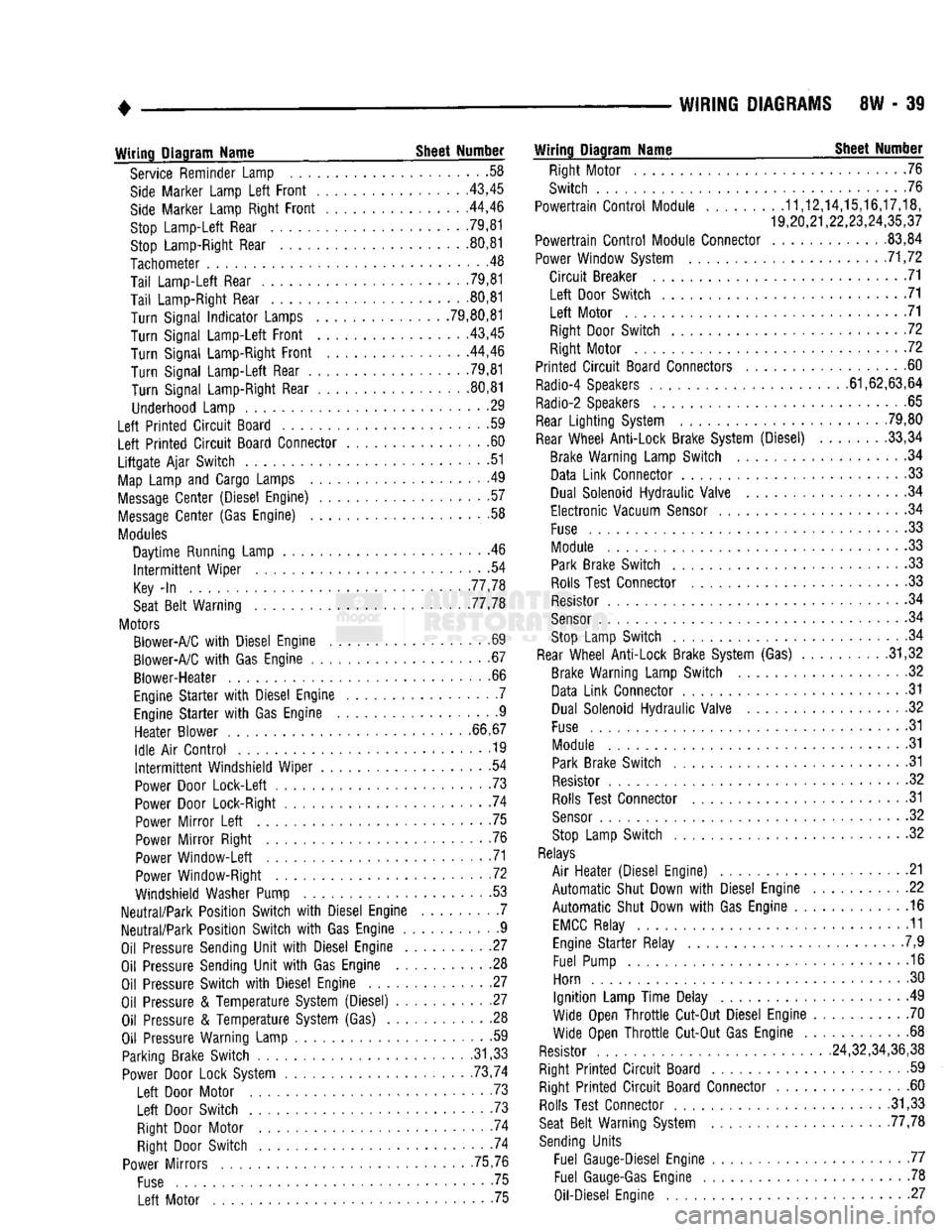
Underhood Lamp 29
Left
Printed
Circuit
Board .59
Left
Printed
Circuit
Board Connector 60
Liftgate
Ajar
Switch
51
Map
Lamp and Cargo Lamps .49
Message
Center
(Diesel Engine) 57
Message
Center
(Gas Engine) .58
Modules
Daytime
Running Lamp . .46
Intermittent
Wiper
.54
Key
-In
77,78
Seat
Belt
Warning 77,78
Motors Blower-A/C
with
Diesel Engine .69
Blower-A/C
with
Gas Engine 67
Blower-Heater
.66
Engine
Starter
with
Diesel Engine . .7 Engine
Starter
with
Gas Engine 9
Heater
Blower
66,67
Idle
Air
Control
............... ........
.19
Intermittent
Windshield
Wiper
54
Power Door
Lock-Left
.73
Power Door Lock-Right 74
Power
Mirror
Left
75
Power
Mirror
Right .76 Power
Window-Left
71
Power Window-Right .72
Windshield Washer Pump 53
Neutral/Park
Position
Switch
with
Diesel Engine 7
Neutral/Park
Position
Switch
with
Gas Engine 9
Oil Pressure Sending
Unit
with
Diesel Engine 27
Oil Pressure Sending
Unit
with
Gas Engine 28 Oil Pressure
Switch
with
Diesel Engine 27
Oil Pressure &
Temperature
System (Diesel) 27 Oil Pressure &
Temperature
System (Gas) . 28
Oil Pressure Warning Lamp • -59 Parking Brake
Switch
.31,33 Power Door Lock System . . 73,74
Left
Door Motor . .73
Left
Door
Switch
. 73
Right Door Motor . -74 Right Door
Switch
74
Power
Mirrors
75,76
Fuse
75
Left
Motor 75
Wiring
Diagram
Name
Sheet
Number
Right Motor 76
Switch
76
Powertrain
Control
Module
........
.11,12,14,15,16,17,18,
19,20,21,22,23,24,35,37
Powertrain
Control
Module Connector .83,84
Power Window System 71,72
Circuit
Breaker 71
Left
Door
Switch
71
Left
Motor 71 Right Door
Switch
72
Right Motor 72
Printed
Circuit
Board Connectors 60
Radio-4 Speakers 61,62,63,64
Radio-2 Speakers 65
Rear
Lighting
System 79,80
Rear
Wheel
Anti-Lock
Brake System (Diesel) 33,34 Brake Warning Lamp
Switch
.34 Data
Link
Connector 33
Dual Solenoid
Hydraulic
Valve 34
Electronic
Vacuum
Sensor
34
Fuse
.33 Module 33 Park Brake
Switch
33
Rolls Test Connector .33 Resistor .34
Sensor
. .34 Stop Lamp
Switch
. .34
Rear
Wheel
Anti-Lock
Brake System (Gas) . .31,32 Brake Warning Lamp
Switch
.32
Data
Link
Connector .31 Dual Solenoid
Hydraulic
Valve 32
Fuse
31
Module 31 Park Brake
Switch
31
Resistor 32 Rolls Test Connector 31
Sensor
32
Stop Lamp
Switch
32
Relays
Air
Heater
(Diesel Engine) .21
Automatic
Shut Down
with
Diesel Engine 22
Automatic
Shut Down
with
Gas Engine 16
EMCC
Relay 11 Engine
Starter
Relay .7,9
Fuel Pump 16
Horn 30
Ignition
Lamp
Time
Delay 49
Wide Open
Throttle
Cut-Out Diesel Engine 70
Wide Open
Throttle
Cut-Out Gas Engine 68
Resistor 24,32,34,36,38
Right
Printed
Circuit
Board 59 Right
Printed
Circuit
Board Connector 60 Rolls Test Connector .31,33
Seat
Belt
Warning System 77,78
Sending
Units
Fuel Gauge-Diesel Engine 77 Fuel
Gauge-Gas
Engine 78
Oil-Diesel Engine 27