1993 DODGE TRUCK service interval
[x] Cancel search: service intervalPage 20 of 1502
•
• —
LUiRICATlON
AND
MAINTENANCE
0 - 1
CONTENTS
page
page
CHASSIS
AND
BODY
28
ENGINE MAINTENANCE
14
DRIVETRAIN
.,,, 22
GENERAL INFORMATION
1
GENERAL
INFORMATION INDEl
page
Classification
of
Lubricants
. 3
Components
Requiring
No
Lubrication
4
Fuel Requirements
. 2
Introduction
1
Lubrication
and
Replacement Parts Recommendation
3
page
Routine Maintenance
2
Starting
Assistance (Jump Starting)
9
Vehicle
Lifting
Recommendations
............ 10
Vehicle Noise
Control
2
Vehicle Towing Recommendations
11
INTRODUCTION
Lubrication and maintenance is divided into re
quired and recommended service tasks. The required service tasks must be completed to verify the emis
sion controls function correctly. The recommended
service tasks should be completed to maintain safety
and durability. This information will assist the service personnel
in providing maximum protection for each owner's
vehicle. Conditions can vary with individual driving habits.
It is necessary to schedule maintenance as a time in
terval as well as a distance interval. It is the owner's responsibility to determine the ap
plicable driving condition. Also to have the vehicle serviced according to the maintenance schedule, and
to pay for the necessary parts and labor. Vehicles with a Gross Vehicle Weight Rating
(GVWR) of 3 855 kg (8,500 lbs.) or less must conform
to light duty emission standards. Vehicles with a Gross Vehicle Weight Rating (GVWR) of 3 856 kg
(8,501 lbs.) or more must conform to heavy duty
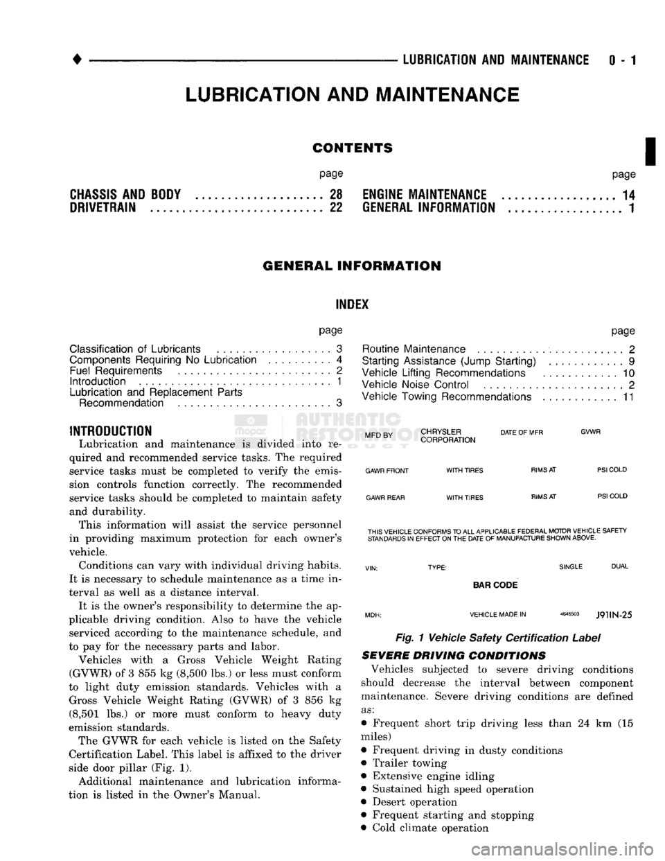
emission standards. The GVWR for each vehicle is listed on the Safety
Certification Label. This label is affixed to the driver
side door pillar (Fig. 1).
Additional maintenance and lubrication informa
tion is listed in the Owner's Manual.
Mm
rv
CHRYSLER
DATE
OF MFR
MFD BY CORPORATION
GVWR
GAWR FRONT
GAWR REAR
WITH
TIRES
WITH
TIRES
RIMS
AT
RIMS
AT
PSI
COLD
PSI
COLD THIS VEHICLE CONFORMS
TO
ALL APPLICABLE FEDERAL MOTOR VEHICLE SAFETY
STANDARDS
IN
EFFECT ON
THE
DATE
OF
MANUFACTURE SHOWN ABOVE.
SINGLE
DUAL
BAR
CODE
VEHICLE MADE
IN
4648503
J9UN-25
Fig. 1 Vehicle Safety
Certification
Label
SEVERE DRIVING
CONDITIONS
Vehicles subjected to severe driving conditions
should decrease the interval between component
maintenance. Severe driving conditions are defined
as:
• Frequent short trip driving less than 24 km (15
miles)
• Frequent driving in dusty conditions
• Trailer towing
• Extensive engine idling
• Sustained high speed operation
• Desert operation
• Frequent starting and stopping
• Cold climate operation
LUBRICATION
AND
MAINTENANCE
Page 21 of 1502
0 - 2
LUBRICATION
AND
MAINTENANCE
• Commercial service
When a vehicle is continuously subjected to severe
driving conditions, lubricate:
• Body components
• All the driveline coupling joints
• Steering linkage More often than normal driving conditions
DUSTY
AREAS
With this type of severe driving condition, special
care should be given to the:
• Engine air cleaner filter
• PCV filter
• Crankcase ventilation system
• Brake booster control valve air filter. Verify that the filters and the associated compo
nents are clean. Also verify that they are functioning
effectively. This will minimize the amount of abra sive particles that enter the engine.
OFF-ROAD
(4WD)
OPERATION
After off-road (4WD) operation, inspect the under
side of the vehicle. Inspect the:
• Tires
• Body structure
• Steering components
• Suspension components • Exhaust system
• Threaded fasteners
HARSH
SURFACE ENVIRONMENTS
After extended operation in harsh environments,
the brake drums, brake linings, and rear wheel bear ings should be inspected and cleaned. This will pre
vent wear and erratic brake action.
ROUTINE MAINTENANCE
The following routine maintenance is recommended
on a monthly basis: TIRES—Inspect the tires for unusual wear/damage.
Determine if the inflation pressure is adequate for
the vehicle load. BATTERY—Inspect and clean the terminals.
Tighten the terminals if necessary. FLUIDS—Determine if the component fluid levels
are acceptable. Add fluid, if necessary. LIGHTS/ELECTRICAL—Test all the electrical sys
tems in the vehicle for proper operation. It is also recommended that the engine oil and the
washer fluid level be determined at each fuel fill-up.
VEHICLE
NOISE CONTROL
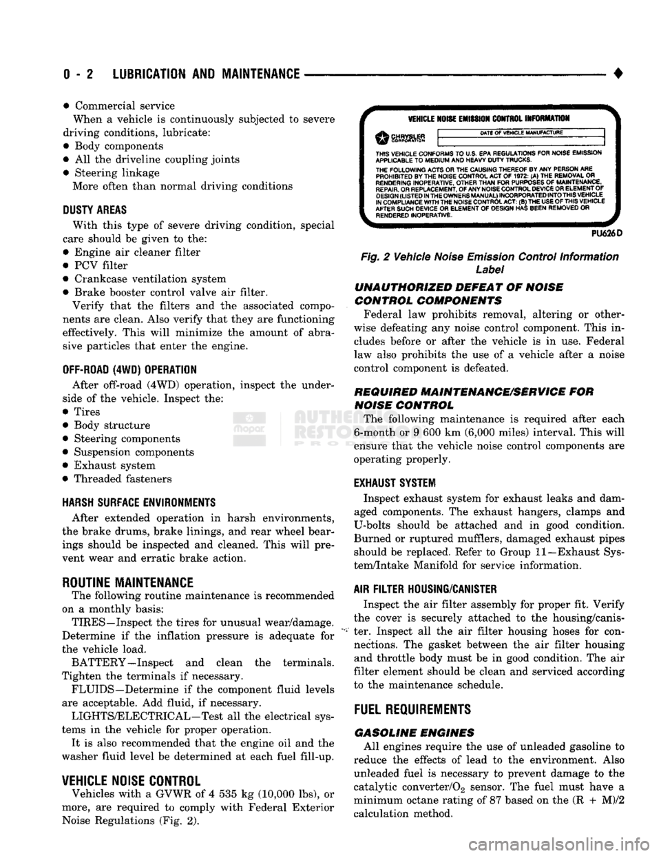
Vehicles with a GVWR of 4 535 kg (10,000 lbs), or
more, are required to comply with Federal Exterior Noise Regulations (Fig. 2).
VEHICLE
NOISE
EMISSION
CONTROL INFORMATION
DATE
OF
VEHICLE
MANUFACTURE
THIS
VEHICLE CONFORMS
TO
U.S. EPA REGULATIONS FOR NOISE EMISSION
APPLICABLE
TO
MEDIUM
AND HEAVY
DUTY
TRUCKS. THE
FOLLOWING
ACTS OR THE CAUSING THEREOF BY ANY PERSON ARE PROHIBITED BY THE NOISE CONTROL ACT
OF 1972. (A) THE
REMOVAL
OR
RENDERING
INOPERATIVE, OTHER
THAN
FOR
PURPOSES
OF
MAINTENANCE,
REPAIR.
OR REPLACEMENT, OF ANY NOISE CONTROL DEVICE OR ELEMENT OF
DESIGN
(LISTED
IN
THE
OWNERS
MANUAL)
INCORPORATED
INTO
THIS
VEHICLE
IN COMPLIANCE
WITH
THE NOISE CONTROL
ACT:
(B) THE
USE
OF
THIS
VEHICLE
AFTER SUCH DEVICE
OR
ELEMENT
OF
DESIGN HAS BEEN REMOVED
OR
RENDERED
INOPERATIVE.
PU626D
Fig.
2 Vehicle
Noise
Emission
Control Information
Label
UNAUTHORIZED
DEFEAT
OF
NOISE
CONTROL COMPONENTS
Federal law prohibits removal, altering or other
wise defeating any noise control component. This in
cludes before or after the vehicle is in use. Federal
law also prohibits the use of a vehicle after a noise
control component is defeated.
REQUIRED MAINTENANCE/SERVICE
FOR
NOISE
CONTROL
The following maintenance is required after each
6-month or 9 600 km (6,000 miles) interval. This will
ensure that the vehicle noise control components are
operating properly.
EXHAUST SYSTEM
Inspect exhaust system for exhaust leaks and dam
aged components. The exhaust hangers, clamps and
U-bolts should be attached and in good condition.
Burned or ruptured mufflers, damaged exhaust pipes should be replaced. Refer to Group 11—Exhaust Sys
tem/Intake Manifold for service information.
AIR
FILTER
HOUSING/CANISTER
Inspect the air filter assembly for proper fit. Verify
the cover is securely attached to the housing/canis
ter. Inspect all the air filter housing hoses for con nections. The gasket between the air filter housing and throttle body must be in good condition. The air
filter element should be clean and serviced according
to the maintenance schedule.
FUEL
REQUIREMENTS
GASOLINE
ENGINES
All engines require the use of unleaded gasoline to
reduce the effects of lead to the environment. Also unleaded fuel is necessary to prevent damage to the
catalytic converter/02 sensor. The fuel must have a
minimum octane rating of 87 based on the (R + M)/2
calculation method.
Page 24 of 1502
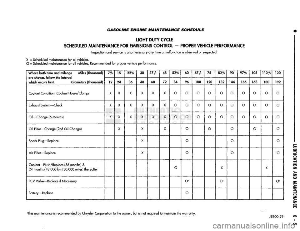
GASOLINE ENGINE MAINTENANCE SCHEDULE
LIGHT
DUTY
CYCLE
SCHEDULED
MAINTENANCE
FOR
EMISSIONS
CONTROL
-
PROPER
VEHICLE
PERFORMANCE
Inspection and service is also necessary any
rime
a
malfunction
is observed or suspected.
X
= Scheduled maintenance for all vehicles.
O
= Scheduled maintenance for all vehicles, Recommended for proper
vehicle
performance.
Where both
time
and mileage Miles (Thousand) are
shown,
follow the
interval
which
occurs
first. Kilometers (Thousand) 7'A
15
22'A
30
37'A
45
52'A
60
67'A
75
82'A
90 97'/2 105 112'A
120
Where both
time
and mileage Miles (Thousand)
are
shown,
follow the
interval
which
occurs
first. Kilometers (Thousand) 12 24
36 48
60 72 84 96 108 120
132 144 156 168 180 192
Coolant
Condition,
Coolant
Hoses/Clomps
X X X X X X
O O O O O
O O O
o
O
Exhaust
System—Check
X
X X X X
X
O O O
o
O
O O
o o o
Oil—Change
(6 months)
X X X X X X
O O O
o o
O O
o o
o
Oil Filter—Change (2nd Oil Change)
X
X X
o o
O
o
o
Spark
Plug—Replace
X
0
o o
Air
Filter—Replace
X
o
O
o
Coolant—Flush/Replace
(36 months) &
24
months/48 000 km
(30,000
miles)
thereafter
O
X
X
PCV
Valve—Replace if
Necessary
O'
O' O'
Battery—Replace
O
This maintenance is recommended by Chrysler Corporation to the owner, but is not
required
to
maintain
the
warranty.
Page 25 of 1502

0 - 6
LUBRICATION
AND
MAINTENANCE
GASOLINE ENGINE MAINTENANCE SCHEDULE
HEAVY
DUTY
CYCLE
Inspection and service is also necessary anytime
a
malfunction is observed or suspected.
When both
time
and mileage
are
Miles (Thousand)
shewn,
follow
the
interval
which occurs first. Kilometers (Thousand) 6
12 18 24
30 36 42 48 54
60 66 72
78
82V2
84 90
96
102 108
When both
time
and mileage
are
Miles (Thousand)
shewn,
follow
the
interval
which occurs first. Kilometers (Thousand) 9.6 19 29
38 48 58 67 77
85 96 106 116
125 132
135
145
154 164
174
Coolant
Condition, Coolant
Hoses/Clamps
X
X X X
X X X X
X X X X
X X X
X X X
Exhaust
System
—
Check
X X X X X X X X X X X
X X X X X
X X
Oil
—
Change
(6
Months)
X X X X X X X
X X
X
X
X
X X X
X X
X
Oil
Filter
—
Change (2nd
Oil
Change)
X X X X
X X
X X
X
Drive Belt Tension
—
Inspect
&
Adjust
X' X
X1
X X' X
Drive Belts (V-Type)
—
Replace
X
Air
Filter/Air
Pump
Air
Filter
—
Replace
X X X
X
Crankcase
Inlet
Air
Filter
(6 &
8
Cyl.
Eng.
Only)
—
Clean
X X
X X
Spark
Plug
—
Replace
X X X
Fuel
Filter
—
Replace as necessary
Coolant
—
Flush/Replace
(36
months)
& 24
months/48
000 km
(30,000
miles)
thereafter
X
EGR
Valve
&
Tube
—
Replace X2
EGR
Tube
—
Clean Passengers
X2
PCV
Valve
—
Replace X2
Vacuum
Emission
Components
—
Replace
X
Ignition Timing
—
Adjust
to
Specs,
as necessary X
Ignition Cables, Distributor Cap
&
Rotor
—
Replace
X
Manifold Heat Control Valve
—
Lubricate
X
Battery
—
Replace X
Oxygen
Sensor
—
Replace
X2
1 For California vehicles, this maintenance is recommended
by
Chrysler Motors
to the
owner but, is not
required
to
maintain the
warranty
on the
air
pump drive
belt.
2 Requires
Emission
Maintenance Reminder Light.
If
so equipped, these parts
are to be
replaced
at the
indicated mileage,
or
when the
emissions
maintenance reminded light remains on continuously
with
the key in the
"on" position, whichever occurs first.
J9100-20
DIESEL
ENGINE
MAINTENANCE
SCHEDULE
HEAVY
DUTY
CYCLE
Inspection
and
service
is
also
necessary
any
time
a
malfunction
is
observed
or
suspected.
Iff both
time
and distance Miles (Thousand)
are listed, use the
interval
that
ends
first. Kilometers (Thousand) 6
12
18 24
30 36 42
4S
54
60 66
72 78
84 90 96
102 108
Iff both
time
and distance Miles (Thousand)
are listed, use the
interval
that
ends
first. Kilometers (Thousand) 9,6 19
29
38 48 58 67
77
85 96 106
116 125 135 145 154
164 174
Coolant
Condition, Coolant
Hoses/Clamps
(12 months)
Coolant
Flush/Replace (36 months) & 24 months/
48 000 km
(30,000
miles)
thereafter
O
Oil—Change
(6 months)
X X X
X X X
X X X X X
X X X X X X
X
Oil Filter—Replace (Every Oil Change)
X X X
X X X
X X
X X X
X
X X X X
X X
Drive Belts—Replace
As
Necessary
X X
X X X X
Air Filter—Replace
X X
X X
Air Filter—Clean (California Only) e
®
• •
Air
Filter
Canister—Clean
o o o
o
Fuel Filter—Service When Necessary
Injection
Pump
Timing & Engine Idle Speed—
Check
& Adjust
©
• 9 • • •
Underhood Rubber/Plastic Components—Inspect/Replace • • • • •
X
— All vehicles
O
— All
vehicles
except
California.
Recommended
for
California.
•
— California only.
Recommended
for all vehicles.
Page 26 of 1502

CHASSIS LUBRICATION
For light
duty
cycle
vehicles
GVW resting
of
3 855 Kg (8,500 lbs ) and
below.
Component
Truck Models
Fittings
Service Interval Lubricant
Center Link
AD1
AD2
AD
4
2
36
000
km
(22,500
miles)
or 2
years Multi-purpose grease
-
NGLI
grade
2
EP
(Multi-Mileage Lubricant)
Drag
Link
Bali
joints
AW1 AW 2
AW
8
2
12
000
km
(7,500
miles)
or 6
months Multi-purpose grease
-
NGLI
grade
2
EP
(Multi-Mileage Lubricant)
Gearshift
Mechanism
Overdrive
4
AD1
1
36
000
km
(22,500
miles)
or 2
years Multi-purpose grease
-
NGLI
grade
2
EP
(Multi-Purpose Lubricant)
Parking Brake Ratio
Lever
Pivot
AD1 AD
2 AD 4
AW1 AW 8
—
36
000
km
(22,500
miles)
or 2
years
Multi-purpose grease
-
NGLI
grade
2
EP
(Multi-Purpose Lubricant)
Propeller Shaft
U-joint
AW1
AW2
AW 8
3
(1
Piece
rear
P/shaft)
12
000
km
(7,500
miles)
or 6
months
Multi-purpose grease
-
NGLI
grade
2
EP
(Multi-Purpose Lubricant)
Propeller Shaft
Slip
Spline
AD1 AD
2
(2
piece P/shaft)
1
36
000
km
(22,500
miles)
or 2
years. For severe
service,
every
4
800
km
(3,000
miles)
or 3
months. Daily,
if
vehicle is operated in
water
Multi-purpose grease
-
NGLI
grade
2
EP
(Multi-Purpose Lubricant)
Suspension
Ball Joints
AD1 AD
2
4
36
000
km
(22,500
miles) or 2 years
—
every
engine
oil change
for
off-highway operation Multi-purpose grease
-
NGLI
grade
2
EP
(Multi-Mileage Lubricant)
Tie Rod Ball Joints
AD1
AD2
AD4
AW1 AW
2
AW8 4
2
36
000
km
(22,500
miles)
or 2
years
12
000
km
(7,500
miles)
or 6
months. Daily,
if
vehicle is operated in
water
Multi-purpose grease
-
NGLI
grade
2
EP
(Multi-Mileage Lubricant)
NP-241 Transfer
Case
Shift
Lever Pivot
AW1
AW2
AW8
—
As
Required
Multi-purpose grease
-
NGLI
grade
2
EP
(Multi-Purpose Lubricant)
Wheel
Stop
AD1 AD
2
AD4
—
36
000
km
(22,500
miles)
or
as
required
Wax Type Lubricant
Constant
Velocity Joint
(Front
P/shaft)
AW1
AW2
AW8 1
12
000
km
(7,500
miles) Multi-purpose grease
-
NGLI
grade
2
EP
(Multi-Purpose Lubricant)
>
J9000-59
>
Page 27 of 1502
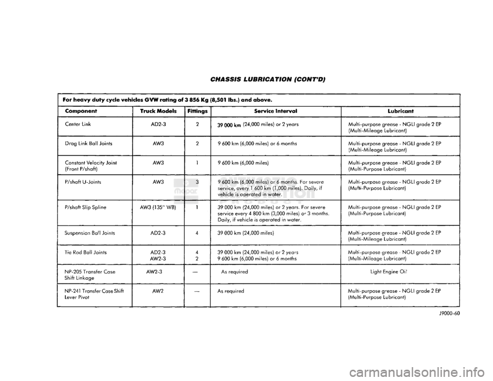
CHASSIS LUBRICATION
(CONT'D)
For
heavy
duty
cycle
vehicles
GVW
rating
of 3 856 Kg
(8,501
Sbs.) and
above.
Component
Truck
Models
Fittings
Service
Interval
Lubricant
Center Link
AD2-3
2
39 000 km (24,000 miles) or 2 years Multi-purpose grease -
NGLI
grade 2 EP
(Multi-Mileage Lubricant)
Drag
Link Ball Joints
AW3
2
9
600 km (6,000 miles) or 6 months
Multi-purpose grease -
NGLI
grade 2 EP
(Multi-Mileage Lubricant)
Constant
Velocity Joint
(Front
P/shaft)
AW3
1
9
600 km (6,000 miles) Multi-purpose grease -
NGLI
grade 2 EP
(Multi-Purpose Lubricant)
P/shaft
U-Joints
AW3
3
9
600 km (6,000 miles) or 6 months. For severe
service,
every
1
600 km (1,000 miles). Daily, if
vehicle is
operated
in
water.
Multi-purpose grease -
NGLI
grade 2 EP
(Multi-Purpose Lubricant)
P/shaft
Slip
Spline
AW3
(135" WB)
1
39
000 km (24,000 miles) or 2 years. For severe
service
every
4 800 km (3,000 miles) or 3 months.
Daily, if vehicle is
operated
in
water.
Multi-purpose
grease -
NGLI
grade 2 EP
(Multi-Purpose Lubricant)
Suspension
Ball Joints
AD2-3
4
39
000 km (24,000 miles) Multi-purpose grease -
NGLI
grade 2 EP
(Multi-Mileage Lubricant)
Tie Rod
Ball
Joints
AD2-3
AW2-3
4
2
39
000 km (24,000
miles)
or 2 years
9
600 km (6,000 miles) or 6 months Multi-purpose grease -
NGLI
grade 2 EP
(Multi-Mileage Lubricant)
NP-205
Transfer
Case
Shift
Linkage
AW2-3
—
As
required
Light
Engine Oil
NP-241
Transfer
Case
Shift
Lever
Pivot
AW2
—
As
required
Multi-purpose grease -
NGLI
grade 2 EP
(Multi-Purpose Lubricant)
J9000-60
Page 34 of 1502

•
LUBRICATION
AND
MAINTENANCE
0 - 15
DIESEL
ENGINES
The Diesel engine oil level indicator is located at
the left center of the engine, above the
fuel
injection
pump (Fig. 3).
Fig.
3
Diesel
Engine
Oil
Dipstick
ACCEPTABLE
OIL
LEVEL
To maintain proper lubrication of an engine, the
engine oil must be maintained at an acceptable level.
For gasoline engines, the acceptable levels are indi cated between the ADD and
FULL
marks on oil
dip
stick. For Diesel engines, the acceptable levels are
indicated between the L (low) and H
(high) marks
on
oil dipstick. The oil level should be checked periodically. The
vehicle should be on a level surface. Wait for
five
minutes after stopping the engine. For gasoline en
gines,
add oil only when the level indicated on the
dipstick is at or below the ADD mark. For Diesel en
gines,
add oil only when the level indicated on the
dipstick is between the L and H marks.
Never oper
ate a Diesel
engine when
the oil
level
is below
the L mark. The distance between the L and H
marks represents 1.9L (2 Qts) engine oil.
CAUTION:
Do not
overfill
an
engine crankcase
with
oil. This
will
cause
oil
aeration
and
result
in a de
crease
in the
engine
oil
pressure.
ENGINE
OIL
CHANGE AND FILTER REPLACEMENT
WARNING: PROTECTIVE CLOTHING
AND
GLOVES SHOULD
BE
WORN. EXPOSED SKIN SHOULD
BE
WASHED
WITH
SOAP
AND
WATER
TO
REMOVE
USED
ENGINE
OIL.
DO NOT
USE
GASOLINE, THIN
NER,
OR
SOLVENTS
TO
REMOVE ENGINE
OIL
FROM
SKIN.
DO NOT
POLLUTE. DISPOSE
OF
USED
ENGINE
OIL
PROPERLY.
ENGINE
OIL
FILTER
All engines are equipped with a throw-away type
oil filter. The same type of filter is recommended
when the filter is changed.
OIL CHANGE
AND
FILTER
REPLACEMENT
Bring engine up to normal operating temperature.
A more complete drainage of oil will result.
(1) Remove the drain hole plug and drain the en
gine oil from the crankcase.
(2) Install the drain hole plug with a replacement
gasket. For gasoline engines, the oil filter should be
replaced during every second engine oil change.
For Diesel engines, the oil filter should be re
placed during every engine oil change.
(3) Rotate the oil filter counterclockwise to remove
it.
(4) Clean the engine cylinder block oil filter boss. (5) Apply a light coat of new engine oil to the rub
ber seal on the oil filter.
(6) Install and hand tighten the oil filter 1/2 to 3/4
of a turn clockwise. (7) Add new engine oil at the fill hole location on
top of the engine cylinder head cover. Wipe off any spilled oil.
(8) Observe the oil level on the dipstick.
CAUTION:
Do not
overfill
the
engine crankcase
with
oil.
(9)
Start the engine. Observe the oil pressure
gauge or warning lamp (as applicable). If the oil
pressure does not increase, stop the engine immedi ately. Check oil level.
COOLING SYSTEM
WARNING:
USE
EXTREME CAUTION WHEN
THE
ENGINE
IS
OPERATING.
DO NOT PUT
YOUR
HANDS NEAR
THE
DRIVE BELT(S), PULLEYS
OR
FAN BLADE.
DO NOT
STAND
IN A
DIRECT LINE
WITH
THE FAN
BLADE.
INSPECTION SCHEDULE
Determine the coolant level. Inspect the cooling
system hoses/clamps after each service interval has
elapsed.
COOLANT LEVEL
It is recommended that the engine coolant level be
inspected at least once a month during periods of hot
weather.
With the engine at normal operating temperature,
check the coolant level in the coolant reserve tank.
The coolant level must be at least above the ADD mark. Add coolant to the coolant reserve tank only.
Page 35 of 1502
0-18
LUBRICATION
AND
MAINTENANCE
•
COOLANT FREEZE PROTECTION
Cooling systems contain a 50/50 mixture of anti
freeze (ethylene glycol) and distilled water. This is
the recommended coolant mixture.
It is recommended that the degree of coolant pro
tection be tested every 12 months. If the coolant is
contaminated or rusty, the cooling system should be
drained, flushed. Refill with a 50/50 mixture of fresh
coolant. Refer to Group 7—Cooling Systems for addi
tional information.
SYSTEM
INSPECTION
WARNING:
IF THE
ENGINE
HAS
BEEN RECENTLY
OPERATED,
DO NOT
REMOVE
THE
RADIATOR
CAP.
THIS WILL AVOID
YOU
BEING SCALDED
WITH
HOT, PRESSURIZED COOLANT.
(1) Test the radiator cap for proper sealing and op
eration. Use caution when removing the radiator cap
to avoid contact with hot coolant. Place a heavy rag
or towel over the cap and turn to the first stop. Do
not press down. Pause to allow the pressure to re
lease through the overflow tube. Then press down
and turn counterclockwise to remove the cap.
(2) Inspect the coolant overflow tubing and the
connections at the coolant reserve tank and at the
radiator.
(3) Inspect the entire cooling system for leaks. A
black-light detector can be used as an aid in detect ing the source of coolant leaks.
(4) Inspect the radiator and air conditioner con
denser fins for debris, etc. (5) If necessary, refer to Group 7—Cooling Systems
for additional information and service procedures.
RADIATOR CAP
The radiator cap must be completely tightened to
provide proper pressure. Inspect and test radiator cap
when cooling system service is performed.
MAIN,
FLUSH
AND
FILL
WARNING: ANTI-FREEZE (ETHYLENE GLYCOL)
IS
POISONOUS.
KEEP
OUT OF THE
REACH
OF
CHIL
DREN.
Drain, flush, and fill the cooling system at the in
terval specified in maintenance schedule. For proper service instructions see Group 7, Cooling System.
HOSES AND
FITTINGS
It is recommended that rubber hoses be periodi
cally inspected. Inspect all hose fittings for looseness and corrosion.
ENGINE
AIR
CLEANER
FILTER
ELEMENT
MAINTENANCE
SCHEDULE
With normal driving conditions, the engine air
cleaner filter element should be replaced:
• Light-Duty Cycle-after each 48 000 km (30,000
miles) interval has elapsed
• Heavy-Duty Cycle-after
each
38 000 km (24,000
miles) interval has elapsed
When the vehicle is operated in dusty areas, the
filter element should be replaced more often.
For Diesel engines, the air filter canister should be
cleaned at the same time the filter is replaced.
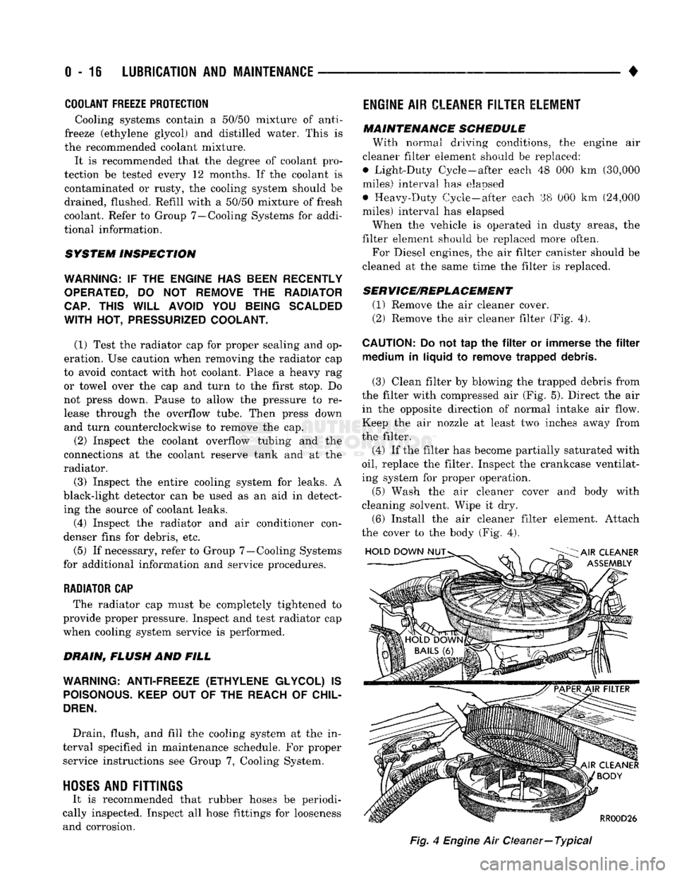
SERVICE/REPLACEMENT
(1) Remove the air cleaner cover.
(2) Remove the air cleaner filter (Fig. 4).
CAUTION:
Do not tap the filter or immerse the filter medium in liquid to remove trapped debris.
(3) Clean filter by blowing the trapped debris from
the filter with compressed air (Fig. 5). Direct the air in the opposite direction of normal intake air flow.
Keep the air nozzle at least two inches away from
the filter.
(4) If the filter has become partially saturated with
oil,
replace the filter. Inspect the crankcase ventilat
ing system for proper operation.
(5) Wash the air cleaner cover and body with
cleaning solvent. Wipe it dry.
(6) Install the air cleaner filter element. Attach
the cover to the body (Fig. 4).
Fig,
4
Engine
Air Oeaner—
Typical