1993 DODGE TRUCK service interval
[x] Cancel search: service intervalPage 52 of 1502
•
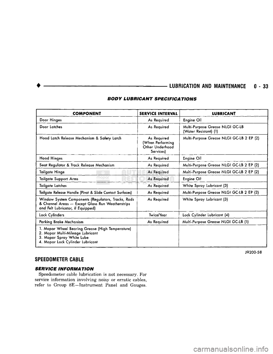
LUBRICATION
AND
MAINTENANCE
0 - 33 BODY LUBRICANT SPECIFICATIONS
COMPONENT
SERVICE
INTERVAL
LUBRICANT
Door
Hinges
As
Required
Engine
Oil
Door
Latches
As
Required Multi-Purpose Grease
NLGI
GC-LB
(Water
Resistant)
(1)
Hood
Latch Release Mechanism
&
Safety Latch
As
Required
(When Performing Other Underhood Services) Multi-Purpose Grease
NLGI
GC-LB
2
EP
(2)
Hood
Hinges
As
Required
Engine
Oil
Seat Regulator
&
Track Release Mechanism
As
Required Multi-Purpose Grease
NLGI
GC-LB
2
EP
(2)
Tailgate Hinge
As
Required Multi-Purpose Grease
NLGI
GC-LB
2
EP
(2)
Tailgate Support Arms
As
Required
Engine
Oil
Tailgate Latches
As
Required
White
Spray Lubricant
(3)
Tailgate Release Handle (Pivot & Slide Contact Surfaces)
As
Required Multi-Purpose Grease
NLGI
GC-LB
2
EP
(2)
Window System Components (Regulators, Tracks,
Rods
&
Channel Areas — Except
Glass
Run Weatherstrips
and
Felt
Lubricator,
if
Equipped)
As
Required
White
Spray Lubricant
(3)
Lock
Cylinders Twice/Year
Lock
Cylinder Lubricant
(4)
Parking Brake Mechanism
As
Required Multi-Purpose Grease
NLGI
GC-LB
(1)
1.
Mopar
Wheel
Bearing Grease (High
Temperature)
2. Mopar Multi-Mileage Lubricant 3. Mopar Spray
White
Lube
4. Mopar Lock Cylinder Lubricant
J9200-58
SPEEDOMETER
CABLE
SERVICE INFORMATION Speedometer cable lubrication is not necessary. For
service information involving noisy or erratic cables,
refer to Group 8E—Instrument Panel and Gauges.
Page 305 of 1502
7 - 34
COOLING SYSTEM
•
WARNING;
DO NOT
REMOVE
THE
CYLINDER
BLOCK DRAIN PLUGS
OR
LOOSEN
THE
RADIATOR
DRAINCOCK
WITH
THE
SYSTEM
HOT AND
UNDER
PRESSURE.
SERIOUS BURNS FROM COOLANT
CAN OCCUR.
(2) Drain the cooling system. Refer to Draining
Cooling System in this group. (3) Remove hose clamps and hoses from radiator.
Remove coolant reserve/overflow tank hose from ra diator filler neck nipple.
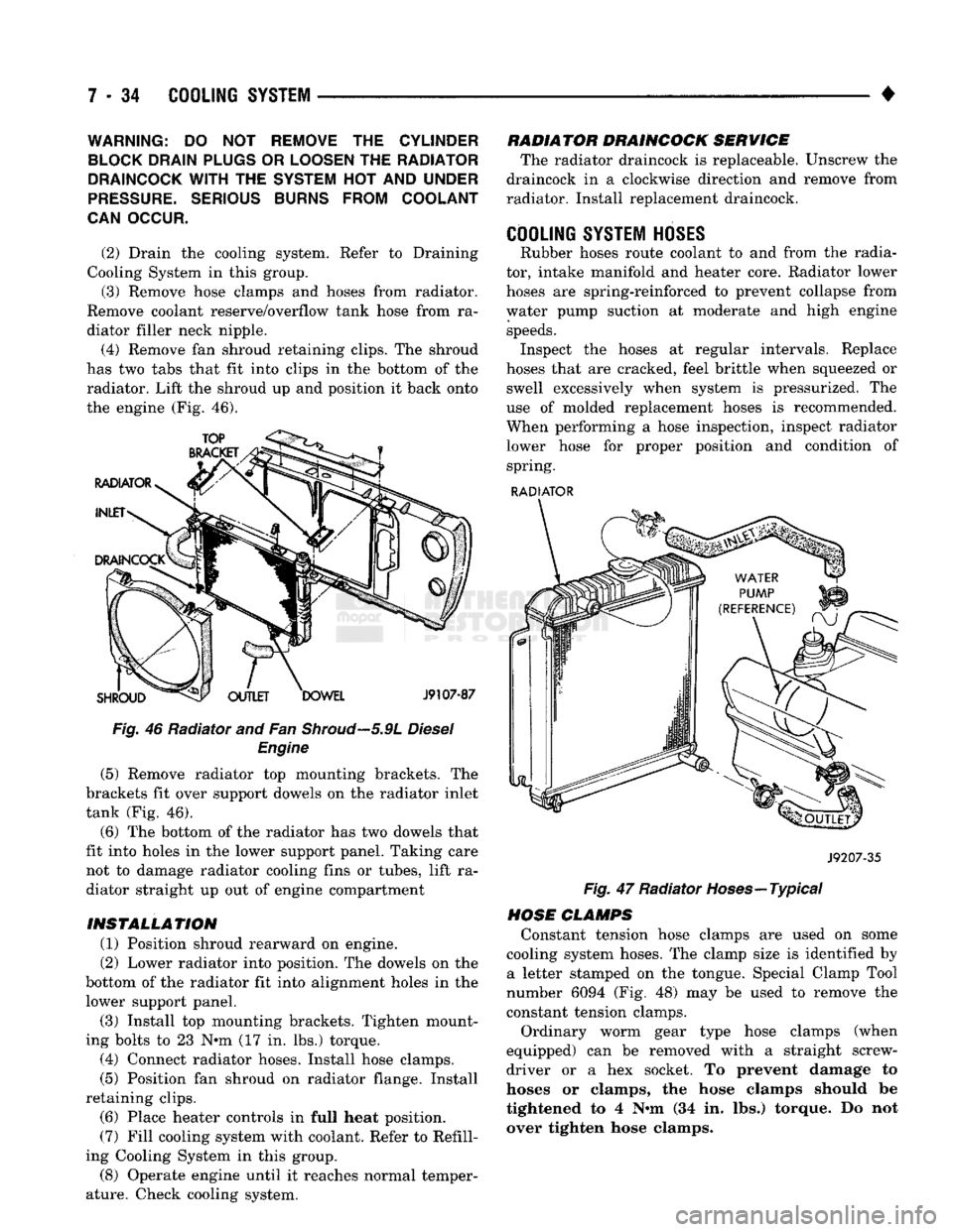
(4) Remove fan shroud retaining clips. The shroud
has two tabs that fit into clips in the bottom of the radiator. Lift the shroud up and position it back onto
the engine (Fig. 46).
Fig. 46 Radiator and Fan
Shroud—5.9L
Diesel Engine
(5) Remove radiator top mounting brackets. The
brackets fit over support dowels on the radiator inlet
tank (Fig. 46).
(6) The bottom of the radiator has two dowels that
fit into holes in the lower support panel. Taking care not to damage radiator cooling fins or tubes, lift ra
diator straight up out of engine compartment
INSTALLATION (1) Position shroud rearward on engine.
(2) Lower radiator into position. The dowels on the
bottom of the radiator fit into alignment holes in the lower support panel.
(3) Install top mounting brackets. Tighten mount
ing bolts to 23 N*m (17 in. lbs.) torque. (4) Connect radiator hoses. Install hose clamps.
(5) Position fan shroud on radiator flange. Install
retaining clips. (6) Place heater controls in full heat position.
(7) Fill cooling system with coolant. Refer to Refill
ing Cooling System in this group.
(8) Operate engine until it reaches normal temper
ature. Check cooling system. RADIATOR DRAINCOCK SERVICE
The radiator draincock is replaceable. Unscrew the
draincock in a clockwise direction and remove from
radiator. Install replacement draincock.
COOLING SYSTEM HOSES
Rubber hoses route coolant to and from the radia
tor, intake manifold and heater core. Radiator lower
hoses are spring-reinforced to prevent collapse from
water pump suction at moderate and high engine speeds. Inspect the hoses at regular intervals. Replace
hoses that are cracked, feel brittle when squeezed or swell excessively when system is pressurized. The
use of molded replacement hoses is recommended.
When performing a hose inspection, inspect radiator lower hose for proper position and condition of spring.
RADIATOR
J9207-35
Fig. 47 Radiator Hoses—Typical
HOSE CLAMPS Constant tension hose clamps are used on some
cooling system hoses. The clamp size is identified by a letter stamped on the tongue. Special Clamp Tool
number 6094 (Fig. 48) may be used to remove the
constant tension clamps.
Ordinary worm gear type hose clamps (when
equipped) can be removed with a straight screw
driver or a hex socket. To prevent damage to
hoses or clamps, the hose clamps should be
tightened to 4 N«m (34 in. lbs.) torque. Do not
over tighten hose clamps.
Page 352 of 1502
•
IGNITION
SYSTEMS
8D
- 1
CONTENTS
page page
COMPONENT IDENTIFICATION/SYSTEM DIAGNOSTICS/SERVICE PROCEDURES
7
OPERATION
1
IGNITION SWITCH
25
COMPONENT REMOVAL/INSTALLATION
..... 18
SPECIFICATIONS
28
COMPONENT
IDENTIFICATION/SYSTEM OPERATION
INDEX
page
Automatic
Shut Down (ASD) Relay
1
Camshaft Position Sensor
2
Crankshaft Position Sensor
2
Distributors
3
Engine Coolant
Temperature
Sensor
...........
4
General
Information
1
page
Ignition
Coil
3
Intake
Manifold Charge
Air
Temperature
Sensor
. . 4
Manifold Absolute Pressure (MAP) Sensor
4
Powertrain
Control
Module (PCM)
. 5
Throttle
Position Sensor
5
GENERAL
INFORMATION
Throughout this group, references
are
made
to
par
ticular vehicle models
by
alphabetical designation
or
by
the
particular vehicle nameplate.
A
chart showing a breakdown
of
alphabetical designations
is
included
in
the
Introduction group
at the
beginning
of
this
manual. 5.9L
gas
powered engines will
be
referred
to as ei
ther: LDC (Light Duty Cycle),
or
HDC (Heavy Duty Cycle). This section
of the
group, Component Identifica
tion/System Operation, will discuss ignition system operation
and
will identify ignition system compo
nents.
For diagnostic procedures
and
adjustments, refer
to
the Diagnostics/Service Procedures section
of
this
group.
For removal
and
installation
of
ignition system
components, refer
to the
Component Removal/Instal
lation section
of
this group. For other useful information, refer
to
On-Board
Di
agnostics
in the
General Diagnosis sections
of
Group
14,
Fuel System
in
this manual. For operation
of the DRB II
Diagnostic Scan Tool,
refer
to the
appropriate Powertrain Diagnostic Proce
dures service manual.
An Ignition specifications section
is
included
at the
end
of
this group.
A
general Maintenance Schedule (mileage intervals)
for
ignition related items
can be
found
in
Group
0,
Lubrication and Maintenance. This
schedule
can
also
be
found
in the
Owners Manual.
IGNITION
SYSTEMS
The ignition systems used
on all
engines
are
basi
cally identical. Similarities
and
differences between
the systems will
be
discussed.
A sequential multi-port fuel injection system
is
used
on all gas
powered engines.
The ignition system
is
controlled
by the
powertrain
control module (PCM)
on all
engines.
The
PCM
was
formerly referred
to as the
SBEC
or
engine control ler.
The ignition system consists
of:
• Spark Plugs
• Ignition Coil
• Secondary Ignition Cables
• Ignition distributor. Contains rotor
and
camshaft
position sensor • Powertrain Control Module (PCM)
• Crankshaft Position Sensor
AUTOMATIC SHUT DOWN (ASD) RELAY
The automatic shut down (ASD) relay
is
located
in
the engine compartment (Fig.
1). As one of its
func
tions,
the ASD
relay will supply battery voltage
to
the ignition coil.
The
ground circuit
for the
ASD
re
lay
is
controlled
by the
powertrain control module (PCM).
The PCM
regulates
ASD
relay operation
by
switching
the
ground circuit on-and-off.
IGNITION
SYSTEMS
Page 365 of 1502

8D
- 14
IGNITION SYSTEMS
• (5) Test the MAP sensor ground circuit at sensor
connector terminal-A (Fig. 19) and PCM connector
terminal-4. Repair the wire harness if necessary.
(6) Test the MAP sensor ground circuit at the
PCM connector between terminal-4 and terminal-11
with an ohmmeter. If the ohmmeter indicates an
open circuit, inspect for a defective sensor ground
connection. Refer to Group 8W, Wiring for location of
this connection. If the ground connection is good, re
place the PCM. If terminal-4 has a short circuit to 12 volts +, correct this condition before replacing the
PCM.
POWERTRAIN
CONTROL MODULE {PCM)
The PCM (formerly called the SBEC or engine -con
troller) is located in the engine compartment (Fig.
20). DATA UNK CONTROL
CONNECTOR MODULE
J9314-164
Fig.
20 PCM Location The ignition system is controlled by the PCM.
For removal and installation of this component, re
fer to the Component Removal/Installation section of
this group.
For diagnostics, refer to the appropriate Powertrain
Diagnostic Procedures service manual for operation
of the DRB II scan tool.
SPARK
PLUGS
For spark plug removal, cleaning, gap adjustment
and installation, refer to the Component Removal/In
stallation section of this group. Spark plug cable boot heat shields are pressed into
the cylinder head to surround each cable boot and
spark plug (Fig. 21). These shields protect the spark
plug boots from damage (due to intense engine heat
generated by the exhaust manifolds) and should not
be removed. After the spark plug cable has been in stalled, the lip of the cable boot should have a small
air gap to the top of the heat shield (Fig. 21). Faulty carbon and/or gas fouled plugs generally
cause hard starting, but they will clean up at higher
engine speeds. Faulty plugs can be identified in a
Fig.
21 Heat
Shields
number of ways: poor fuel economy, power loss, de
crease in engine speed, hard starting and, in general,
poor engine performance.
Remove the spark plugs and examine them for
burned electrodes and fouled, cracked or broken por celain insulators. Keep plugs arranged in the order
in which they were removed from the engine. An iso
lated plug displaying an abnormal condition indi
cates that a problem exists in the corresponding
cylinder. Replace spark plugs at the intervals recom
mended in the maintenance chart in Group 0, Lubri
cation and Maintenance.
Spark plugs that have low mileage may be cleaned
and reused if not otherwise defective. Refer to the
following Spark Plug Condition section of this group.
CONDITION
NORMAL OPERATING
The few deposits present on the spark plug will
probably be light tan or slightly gray in color. This is evident with most grades of commercial gasoline (Fig. 22). There will not be evidence of electrode
burning. Gap growth will not average more than ap proximately 0.025 mm (.001 in) per 1600 km (1000
miles) of operation. Spark plugs that have normal
wear can usually be cleaned, have the electrodes filed, have the gap set and then be installed.
Some fuel refiners in several areas of the United
States have introduced a manganese additive (MMT)
for unleaded fuel. During combustion, fuel with
MMT causes the entire tip of the spark plug to be coated with a rust colored deposit. This rust color can
be misdiagnosed as being caused by coolant in the combustion chamber. Spark plug performance is not affected by MMT deposits.
COLD
FOULING/CARBON FOULING
Cold fouling is sometimes referred to as carbon
fouling. The deposits that cause cold fouling are ba-
Page 619 of 1502
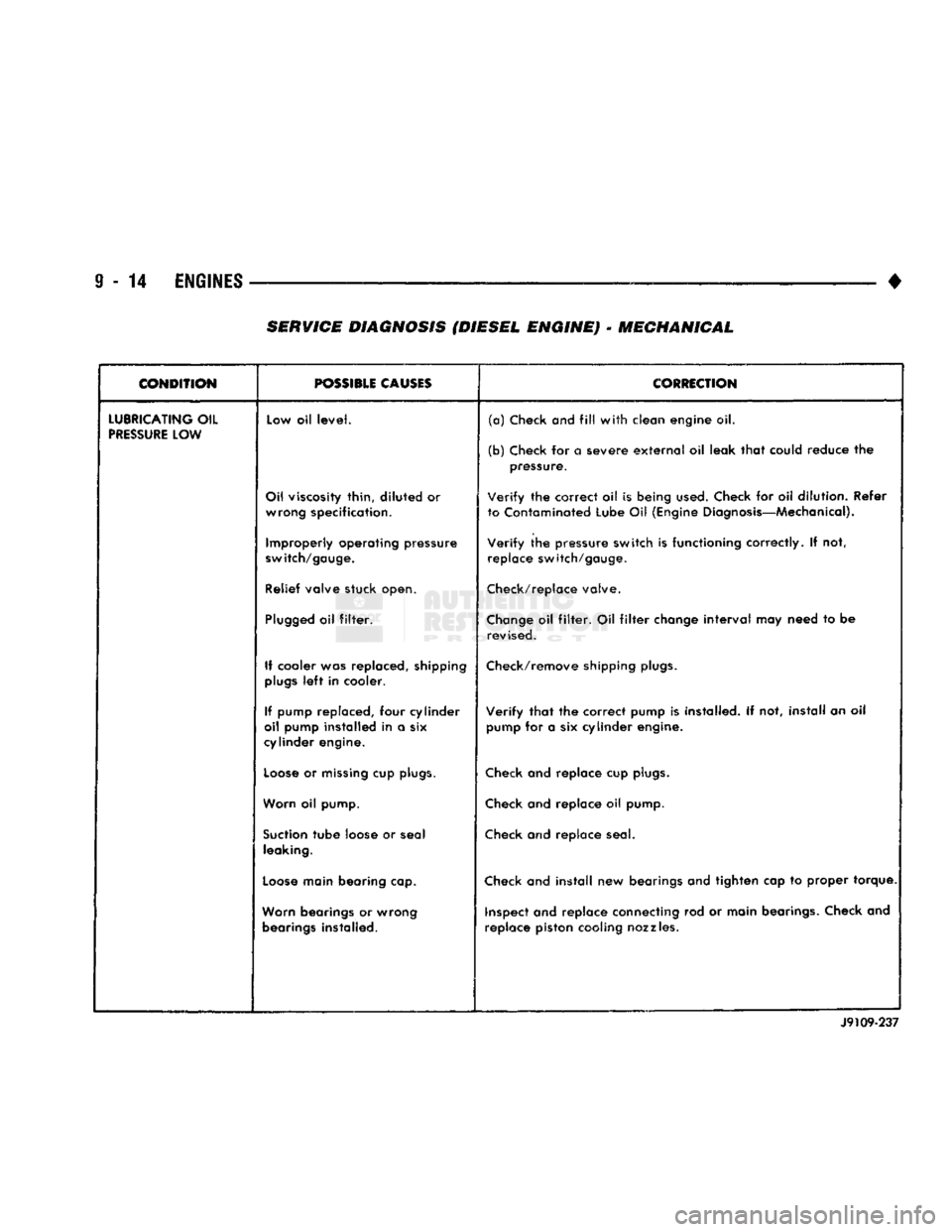
9
- 14
ENGINES
— — — •
SERVICE
DIAGNOSIS (DIESEL ENGINE)
•
MECHANICAL
CONDITION
r— ———
POSSIBLE
CAUSES
CORRECTION
LUBRICATING
OIL
PRESSURE
LOW Low oil
level.
(a)
Check
and
fill
with
clean engine oil.
(b) Check for a severe
external
oil leak
that
could reduce the pressure.
Oil viscosity thin,
diluted
or wrong specification.
Verify
the correct oil is being
used.
Check for oil dilution. Refer
to Contaminated Lube Oil (Engine Diagnosis—Mechanical).
Improperly operating pressure
switch/gauge.
Verify
the pressure switch is functioning correctly. If not,
replace switch/gauge.
Relief valve stuck open. Check/replace valve.
Plugged
oil
filter.
Change
oil
filter.
Oil
filter
change
interval
may need to be
revised.
If cooler was replaced, shipping
plugs
left
in cooler. Check/remove shipping
plugs.
If pump replaced, four cylinder
oil pump installed in a six
cylinder engine.
Verify
that
the correct pump is installed. If not, install an oil
pump for a six cylinder engine.
Loose
or
missing
cup
plugs.
Check and replace cup
plugs.
Worn oil pump. Check and replace oil pump.
Suction
tube
loose or seal leaking. Check and replace seal.
Loose
main bearing cap. Check and
install
new bearings and tighten cap to proper torque.
Worn bearings or wrong bearings installed. inspect and replace connecting rod or main bearings. Check and
replace piston cooling nozzles.
J9109-237
Page 620 of 1502
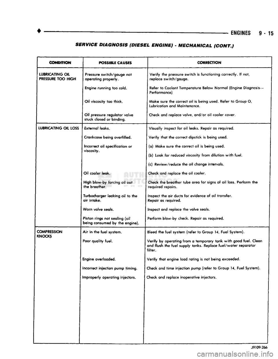
•
• —
ENGINES
9 - 15
CONDITION
POSSIBLE CAUSES
CORRECTION
LUBRICATING
OIL
PRESSURE
TOO
HIGH
Pressure
switch/gauge
not
operating
properly.
Verify
the
pressure
switch
is
functioning
correctly.
If not,
replace
switch/gauge.
Engine
running
too
cold.
Refer
to
Coolant
Temperature
Below
Normal
(Engine
Diagnosis-
Performance)
Oil
viscosity
too thick. Make
sure
the
correct
oil Is
being
used.
Refer
to
Group
O,
Lubrication
and
Maintenance.
Oil
pressure
regulator
valve
stuck
closed
or
binding.
Check
and replace valve, and/or oil cooler cover.
LUBRICATING
OIL
LOSS
External
leaks.
Visually
inspect for oil
leaks.
Repair as required.
Crankcase
being
overfilled. Verify that the correct dipstick is being
used.
incorrect
oil specification or
viscosity.
(a) Make sure the correct oil is being
used.
(b)
Look
for reduced
viscosity
from dilution with fuel.
(c) Review/reduce the oil
change
intervals.
Oil
cooler
leak.
Check
and replace the oil cooler.
High
blow-by
forcing oil out
the breather.
Check
the breather tube area for
signs
of oil
loss.
Perform the
required repairs.
Turbocharger
leaking
oil to the
air intake.
Inspect
the air
ducts
for evidence of oil transfer.
Repair
as required.
Worn
valve
seals.
Inspect
and replace the valve
seals.
Piston
rings
not
sealing
(oil
being
consumed
by the
engine).
Perform
blow-by check. Repair as required.
COMPRESSION
KNOCKS
Air in the
fuel
system.
Poor
quality
fuel.
Bleed
the fuel
system
(refer
to
Group
14, Fuel
System).
Verify by operating from a temporary tank with
good
fuel. Clean
and
flush the fuel
supply
tanks.
Replace fuel/water separator
filter.
Engine
overloaded. Verify that engine load rating is not being exceeded.
Incorrect injection
pump
timing.
Check
and time injection pump
(refer
to
Group
14, Fuel
System).
Improperly
operating
injectors.
Check
and replace inoperative injectors. J9109-266 SERVICE DIAGNOSIS (DIESEL ENGINE) - MECHANICAL (CONT.)
Page 910 of 1502
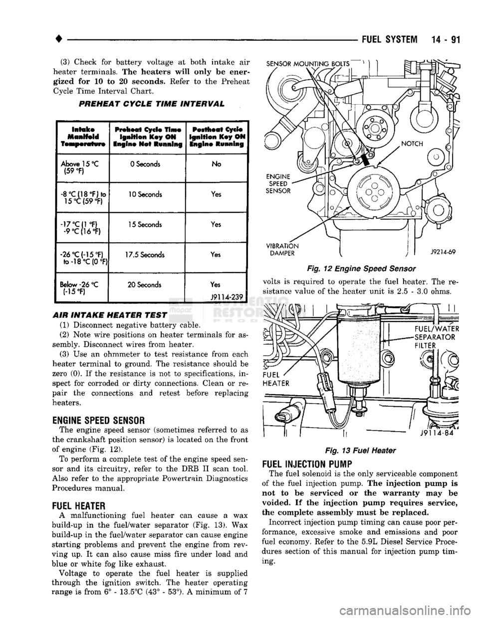
(3) Check for battery voltage at both intake air
heater terminals. The heaters will only be ener gized for 10 to 20 seconds. Refer to the Preheat Cycle Time Interval Chart.
PREHEAT
CYCLE
TIME
INTERVAL
SENSOR
MOUNTING
BOLTS
Intake
Manifold
temperature
Preheat
Cycle
Time
Ignition
Key ON
Engine
Net
Running
Pestheat
Cycle
Ignition
Key ON Ingin©
Running
Above 15 °C (59
°F)
0 Seconds
No
-8°C{18°F)*o 15°C(59
°F)
10 Seconds
Yes
-17°C{1 °F) •9°C(16°F) 15 Seconds
Yes
-26°C(-15°F) fo-18°C (0
°F)
17.5 Seconds
Yes
Below
-26
°C
(15T) 20 Seconds
Yes
J9114-239
AIR INTAKE HEATER TEST (1) Disconnect negative battery cable.
(2) Note wire positions on heater terminals for as
sembly. Disconnect wires from heater.
(3) Use an ohmmeter to test resistance from each
heater terminal to ground. The resistance should be
zero (0). If the resistance is not to specifications, in spect for corroded or dirty connections. Clean or re
pair the connections and retest before replacing
heaters.
ENGINE
SPEED
SENSOR
The engine speed sensor (sometimes referred to as
the crankshaft position sensor) is located on the front
of engine (Fig. 12). To perform a complete test of the engine speed sen
sor and its circuitry, refer to the DRB II scan tool.
Also refer to the appropriate Powertrain Diagnostics
Procedures manual.
FUEL
HEATER
A malfunctioning fuel heater can cause a wax
build-up in the fuel/water separator (Fig. 13). Wax
build-up in the fuel/water separator can cause engine starting problems and prevent the engine from rev
ving up. It can also cause miss fire under load and
blue or white fog like exhaust. Voltage to operate the fuel heater is supplied
through the ignition switch. The heater operating
range is from 6° - 13.5°C (43° - 53°). A minimum of 7
VIBRATION
DAMPER
J9214-69
Fig.
12
Engine
Speed
Sensor
volts is required to operate the fuel heater. The re
sistance value of the heater unit is 2.5 - 3.0 ohms.
««.
* rr ,,
J9114-84
Fig.
13
Fuel
Heater
FUEL
INJECTION
PUMP
The fuel solenoid is the only serviceable component
of the fuel injection pump. The injection pump is
not to be serviced or the warranty may be
voided. If the injection pump requires service,
the complete assembly must be replaced. Incorrect injection pump timing can cause poor per
formance, excessive smoke and emissions and poor
fuel economy. Refer to the 5.9L Diesel Service Proce
dures section of this manual for injection pump tim
ing.
Page 912 of 1502
•
FUEL SYSTEM
14-93 There is a drain at the bottom of the separator fil
ter (Fig. 13). Place a drain pan under the drain tube. With the engine not running, hold the drain open
until all water and contaminants have been removed and clean fuel exits the drain. Dispose of mixture in
drain pan according to applicable regulations.
If excess water gathers in separator/filter in a short
time,
the fuel tank must be removed, drained and cleaned.
HIGH
PRESSURE FUEL LINE RESTRICTIONS
High pressure fuel line leaks can cause starting
problems, poor engine performance and engine miss under load. Restricted high pressure lines can cause starting problems, poor engine performance, engine
miss under load and black smoke from exhaust.
WARNING:
USE
EXTREME
CAUTION
WHEN
IN
SPECTING
FOR HIGH
PRESSURE
FUEL
LEAKS.
IN
SPECT
FOR HIGH
PRESSURE
FUEL
LEAKS
WITH
A
SHEET
OF
CARDBOARD.
HIGH
FUEL
INJECTION
PRESSURE
CAN
CAUSE
PERSONAL
INJURY
IF
CONTACT
IS
MADE
WITH
THE
SKIN.
Start the engine. Move the cardboard over the high
pressure fuel lines and check for fuel spray onto the cardboard. If a high pressure line connection is leak
ing, bleed the system and tighten the connection. Re
fer to the 5.9L Diesel Service Procedures section for air bleeding procedures. Replace damaged, restricted
or leaking high pressure fuel lines with the correct replacement line.
CAUTION:
The
high pressure
fuel
lines must
be
clamped securely
in
place
in the
holders.
The
lines cannot contact each other
or
other components.
Do
not
attempt
to
weld high pressure
fuel
lines
or to
repair lines
that
are
damaged. Only
use the
recom
mended lines when replacement
of
high pressure
fuel
line
is
necessary.
KSB
SOLENOID
The KSB solenoid will click when it is energized
and de-energized. If the solenoid does not click when 12 volts is sup
plied to it, replace the solenoid.
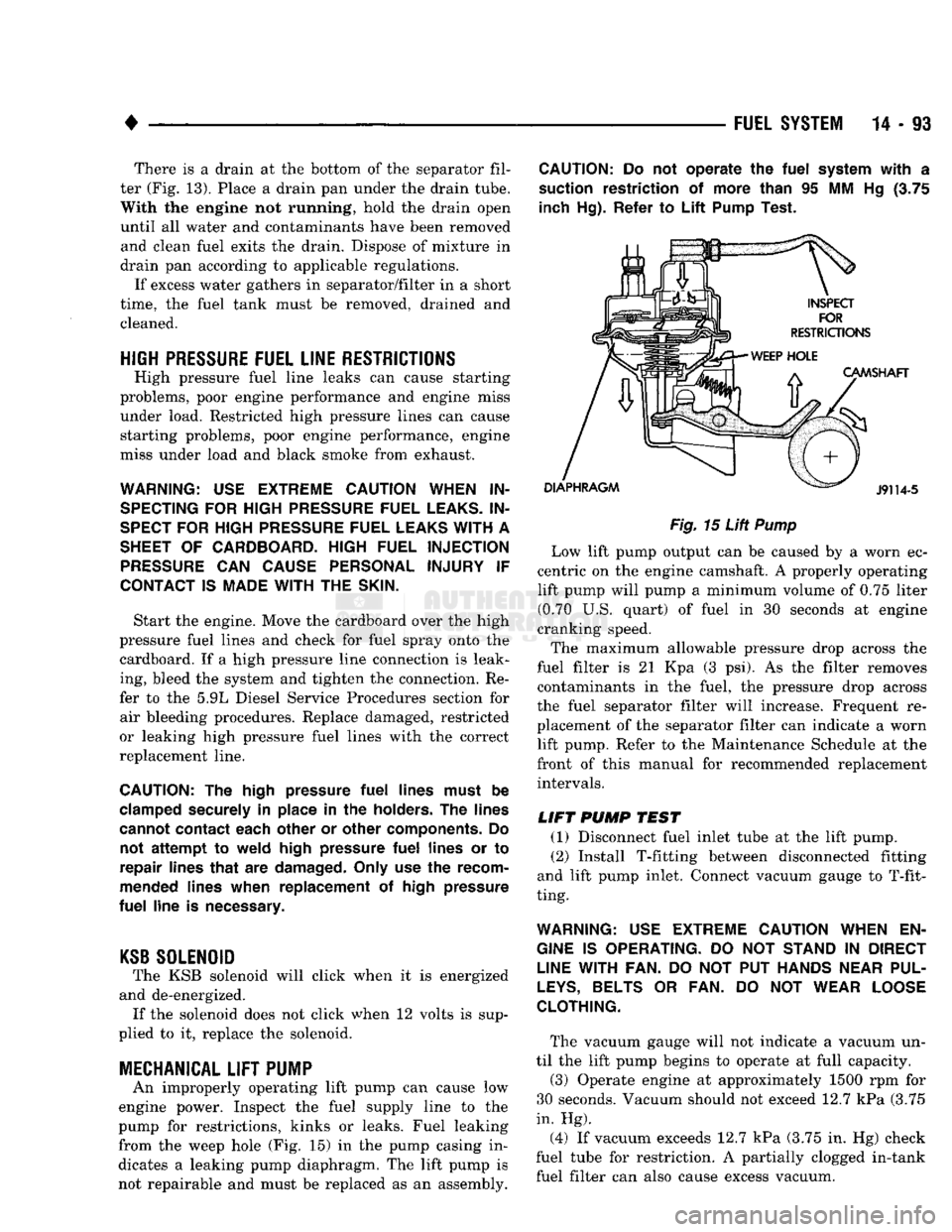
MECHANICAL
LIFT
PUMP
An improperly operating lift pump can cause low
engine power. Inspect the fuel supply line to the
pump for restrictions, kinks or leaks. Fuel leaking
from the weep hole (Fig. 15) in the pump casing in
dicates a leaking pump diaphragm. The lift pump is not repairable and must be replaced as an assembly.
CAUTION:
Do not
operate
the
fuel
system
with
a
suction restriction
of
more than
95 MM Hg (3.75
inch Hg). Refer
to
Lift
Pump Test.
Fig.
15
Lift
Pump
Low lift pump output can be caused by a worn ec
centric on the engine camshaft. A properly operating lift pump will pump a minimum volume of 0.75 liter (0.70 U.S. quart) of fuel in 30 seconds at engine
cranking speed.
The maximum allowable pressure drop across the
fuel filter is 21 Kpa (3 psi). As the filter removes contaminants in the fuel, the pressure drop across
the fuel separator filter will increase. Frequent re
placement of the separator filter can indicate a worn lift pump. Refer to the Maintenance Schedule at the
front of this manual for recommended replacement intervals.
LIFT
PUMP
TEST
(1) Disconnect fuel inlet tube at the lift pump. (2) Install T-fitting between disconnected fitting
and lift pump inlet. Connect vacuum gauge to T-fit
ting.
WARNING:
USE
EXTREME
CAUTION
WHEN
EN
GINE
IS
OPERATING.
DO NOT
STAND
IN
DIRECT
LINE
WITH FAN.
DO NOT PUT
HANDS
NEAR
PUL
LEYS,
BELTS
OR FAN. DO NOT
WEAR
LOOSE
CLOTHING.
The vacuum gauge will not indicate a vacuum un
til the lift pump begins to operate at full capacity.
(3) Operate engine at approximately 1500 rpm for
30 seconds. Vacuum should not exceed 12.7 kPa (3.75
in. Hg).
(4) If vacuum exceeds 12.7 kPa (3.75 in. Hg) check
fuel tube for restriction. A partially clogged in-tank fuel filter can also cause excess vacuum.