1993 DODGE TRUCK seat adjustment
[x] Cancel search: seat adjustmentPage 48 of 1502
•
LUBRICATION
AND
MAINTENANCE
0 - 29
POWER STEERING SYSTEM
SERVICE SCHEDULE
FLUID
LEWEL
WARNING.
THE
POWER
STEERING
FLUID LEVEL
SHOULD
ALWAYS
BE
CHECKED
WITH THE EN
GINE
OFF TO
PREVENT
PERSONAL
INJURY.
The power steering fluid should be checked when
ever the engine is being serviced for other reasons. Clean the outside of the cap before removing. The
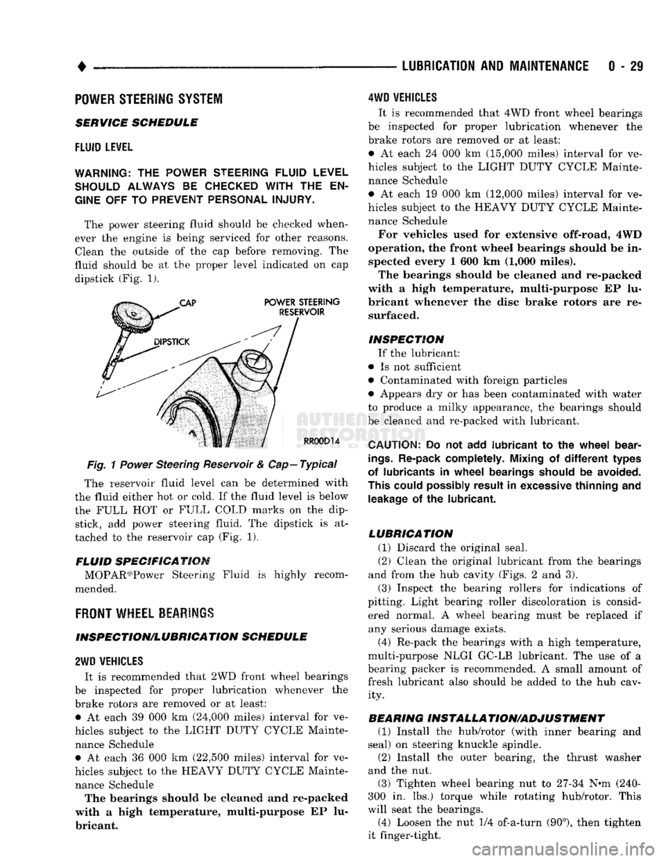
fluid should be at the proper level indicated on cap dipstick (Fig. 1).
Fig.
1
Power
Steering Reservoir & Cap—Typical
The reservoir fluid level can be determined with
the fluid either hot or cold. If the fluid level is below
the FULL HOT or FULL COLD marks on the dip stick, add power steering fluid. The dipstick is at
tached to the reservoir cap (Fig. 1).
FLUID SPECIFICATION MOPAR03)Power Steering Fluid is highly recom
mended.
FRONT
WHEEL BEARINGS
INSPECTION/LUBRICATION SCHEDULE
2WD
VEHICLES
It is recommended that 2WD front wheel bearings
be inspected for proper lubrication whenever the
brake rotors are removed or at least: • At each 39 000 km (24,000 miles) interval for ve
hicles subject to the LIGHT DUTY CYCLE Mainte nance Schedule • At each 36 000 km (22,500 miles) interval for ve
hicles subject to the HEAVY DUTY CYCLE Mainte nance Schedule The bearings should be cleaned and re-packed
with a high temperature, multi-purpose EP lu
bricant.
4WD
VEHICLES
It is recommended that 4WD front wheel bearings
be inspected for proper lubrication whenever the
brake rotors are removed or at least:
• At each 24 000 km (15,000 miles) interval for ve
hicles subject to the LIGHT DUTY CYCLE Mainte nance Schedule
• At each 19 000 km (12,000 miles) interval for ve
hicles subject to the HEAVY DUTY CYCLE Mainte nance Schedule
For vehicles used for extensive off-road, 4WD
operation, the front wheel bearings should be in spected every 1 600 km (1,000 miles).
The bearings should be cleaned and re-packed
with a high temperature, multi-purpose EP lu
bricant whenever the disc brake rotors are re surfaced.
INSPECTION If the lubricant:
• Is not sufficient
• Contaminated with foreign particles
• Appears dry or has been contaminated with water
to produce a milky appearance, the bearings should
be cleaned and re-packed with lubricant.
CAUTION:
Do not add
lubricant
to the
wheel
bear
ings.
Re-pack completely. Mixing
of
different
types
of lubricants
in
wheel
bearings should
be
avoided.
This could possibly result
in
excessive thinning
and
leakage
of the
lubricant.
LUBRICATION (1) Discard the original seal.
(2) Clean the original lubricant from the bearings
and from the hub cavity (Figs. 2 and 3).
(3) Inspect the bearing rollers for indications of
pitting. Light bearing roller discoloration is consid ered normal. A wheel bearing must be replaced if any serious damage exists.
(4) Re-pack the bearings with a high temperature,
multi-purpose NLGI GC-LB lubricant. The use of a
bearing packer is recommended. A small amount of fresh lubricant also should be added to the hub cav ity.
BEARING INSTALLA TION/ADJUSTMENT (1) Install the hub/rotor (with inner bearing and
seal) on steering knuckle spindle.
(2) Install the outer bearing, the thrust washer
and the nut.
(3) Tighten wheel bearing nut to 27-34 N^m (240-
300 in. lbs.) torque while rotating hub/rotor. This
will seat the bearings.
(4) Loosen the nut 1/4 of-a-turn (90°), then tighten
it finger-tight.
Page 75 of 1502
2
- 22
FRONT SUSPENSION
AND
AXLE
——
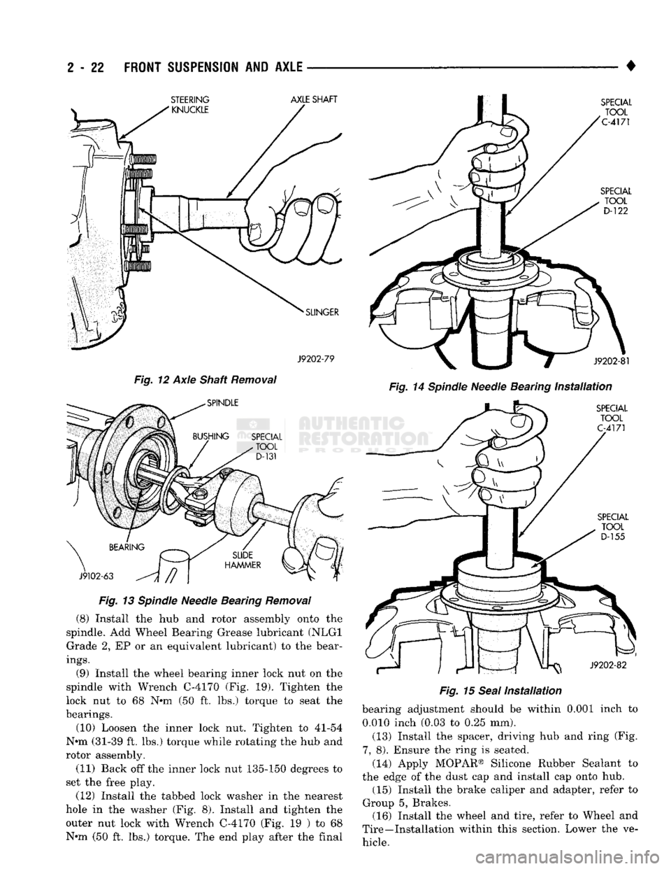
J9202-79
Fig. 12 Axle Shaft Removal
Fig. 13 Spindle Needle Bearing Removal (8) Install the hub and rotor assembly onto the
spindle. Add Wheel Bearing Grease lubricant (NLGI Grade 2, EP or an equivalent lubricant) to the bear
ings.
(9) Install the wheel bearing inner lock nut on the
spindle with Wrench C-4170 (Fig. 19). Tighten the
lock nut to 68 N*m (50 ft. lbs.) torque to seat the
bearings.
(10) Loosen the inner lock nut. Tighten to 41-54
N*m (31-39 ft. lbs.) torque while rotating the hub and
rotor assembly.
(11) Back off the inner lock nut 135-150 degrees to
set the free play.
(12) Install the tabbed lock washer in the nearest
hole in the washer (Fig. 8). Install and tighten the outer nut lock with Wrench C-4170 (Fig. 19 ) to 68
N«m (50 ft. lbs.) torque. The end play after the final •
Fig. 14 Spindle Needle Bearing Installation Fig. 15 Seal Installation bearing adjustment should be within 0.001 inch to
0.010 inch (0.03 to 0.25 mm).
(13) Install the spacer, driving hub and ring (Fig.
7,
8). Ensure the ring is seated.
(14) Apply MOPAR® Silicone Rubber Sealant to
the edge of the dust cap and install cap onto hub. (15) Install the brake caliper and adapter, refer to
Group 5, Brakes. (16) Install the wheel and tire, refer to Wheel and
Tire—Installation within this section. Lower the ve hicle. STEERING
AXLE
SHAFT
Page 89 of 1502
2
- 36
FRONT
SUSPENSION
AND
AXLE
• • Pinion gear mate shaft (align holes in shaft and
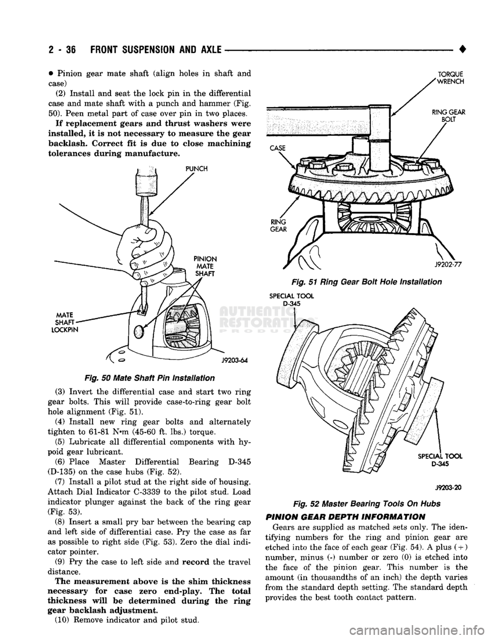
case) (2) Install and seat the lock pin in the differential
case and mate shaft with a punch and hammer (Fig.
50).
Peen metal part of case over pin in two places.
If replacement gears and thrust washers were
installed, it is not necessary to measure the gear
backlash. Correct fit is due to close machining
tolerances during manufacture.
Fig.
50
Mate
Shaft Pin
installation
(3) Invert the differential case and start two ring
gear bolts. This will provide case-to-ring gear bolt
hole alignment (Fig. 51).
(4) Install new ring gear bolts and alternately
tighten to 61-81 N*m (45-60 ft. lbs.) torque.
(5) Lubricate all differential components with hy
poid gear lubricant.
(6) Place Master Differential Bearing D-345
(D-135) on the case hubs (Fig. 52).
(7) Install a pilot stud at the right side of housing.
Attach Dial Indicator C-3339 to the pilot stud. Load
indicator plunger against the back of the ring gear (Fig. 53).
(8) Insert a small pry bar between the bearing cap
and left side of differential case. Pry the case as far as possible to right side (Fig. 53). Zero the dial indi
cator pointer.
(9) Pry the case to left side and record the travel
distance. The measurement above is the shim thickness
necessary for case zero end-play. The total
thickness will be determined during the ring gear backlash adjustment. (10) Remove indicator and pilot stud.
TORQUE
Fig.
51
Ring
Gear
Bolt
Hole
Installation
SPECIAL
TOOL
D-345
J9203-20
Fig.
52 Master Bearing Tools On
Hubs
PINION GEAR DEPTH INFORMATION Gears are supplied as matched sets only. The iden
tifying numbers for the ring and pinion gear are etched into the face of each gear (Fig. 54). A plus
(
+ )
number, minus (-) number or zero (0) is etched into
the face of the pinion gear. This number is the amount (in thousandths of an inch) the depth varies
from the standard depth setting. The standard depth
provides the best tooth contact pattern.
Page 93 of 1502
2
- 40
FRONT
SUSPENSION
AND
AXLE
•
SHIM PACKS
RY660
J9103-21
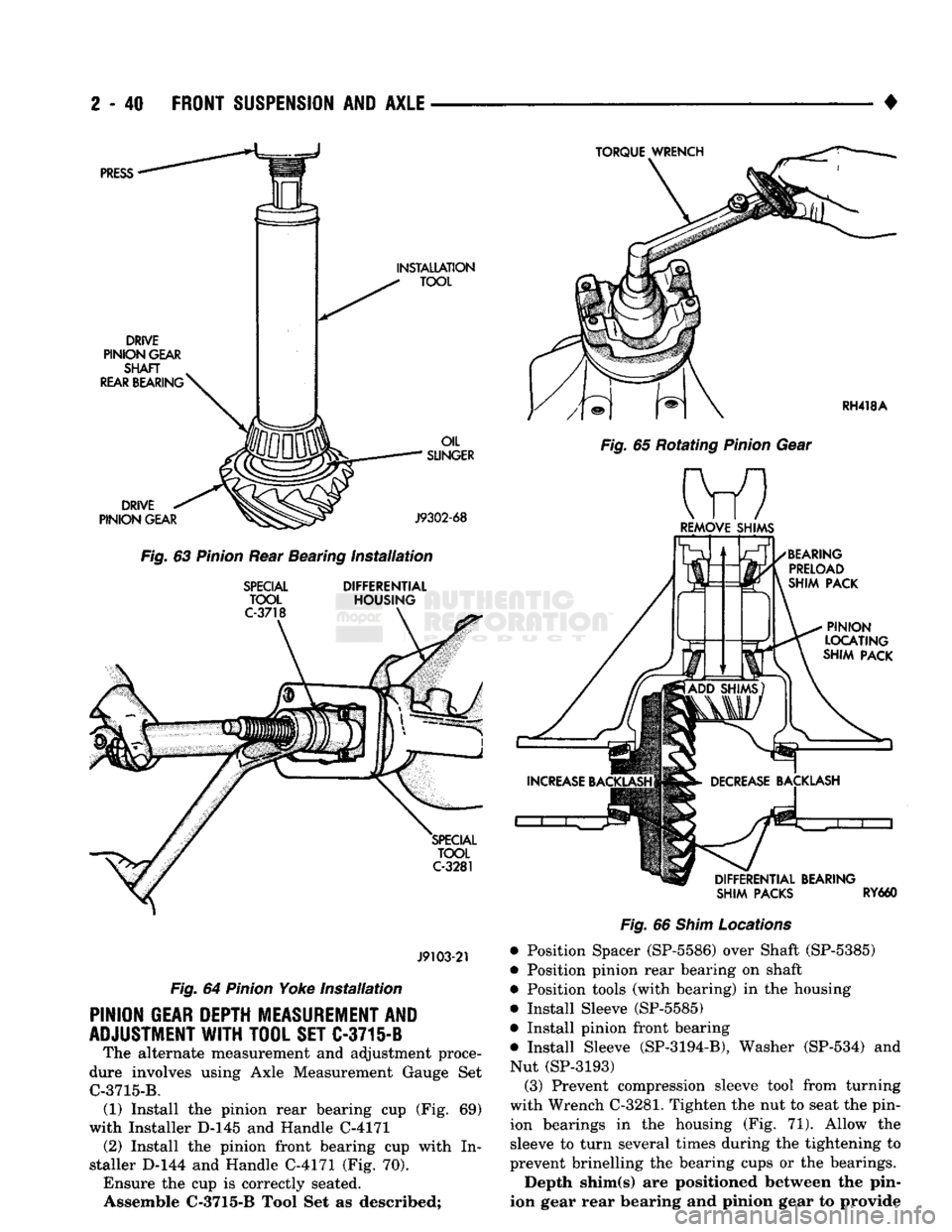
Fig.
64
Pinion
Yoke
Installation
PINION
GEAR
DEPTH
MEASUREMENT AND
ADJUSTMENT
WITH
TOOL
SET
C-3715-B The alternate measurement and adjustment proce
dure involves using Axle Measurement Gauge Set C-3715-B. (1) Install the pinion rear bearing cup (Fig. 69)
with Installer D-145 and Handle C-4171 (2) Install the pinion front bearing cup with In
staller D-144 and Handle C-4171 (Fig. 70). Ensure the cup is correctly seated.
Assemble
C-3715-B
Tool Set as described;
Fig.
66
Shim
Locations
• Position Spacer (SP-5586) over Shaft (SP-5385)
• Position pinion rear bearing on shaft
• Position tools (with bearing) in the housing
• Install Sleeve (SP-5585)
• Install pinion front bearing
m Install Sleeve (SP-3194-B), Washer (SP-534) and Nut (SP-3193) (3) Prevent compression sleeve tool from turning
with Wrench C-3281. Tighten the nut to seat the pin
ion bearings in the housing (Fig. 71). Allow the
sleeve to turn several times during the tightening to
prevent brinelling the bearing cups or the bearings.
Depth shim(s) are positioned between the pin
ion gear rear bearing and pinion gear to provide
Page 108 of 1502
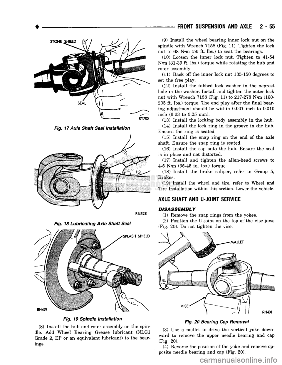
•
Fig.
17 Axle Shaft
Seal
Installation
Fig.
19
Spindle
Installation
(8) Install the hub and rotor assembly on the spin
dle.
Add Wheel Bearing Grease lubricant (NLGI Grade 2, EP or an equivalent lubricant) to the bear
ings.
FRONT
SUSPENSION
AND
AXLE
2 - 51
Fig.
20 Bearing Cap
Removal
(3) Use a mallet to drive the vertical yoke down
ward to remove the upper needle bearing and cap (Fig. 20).
(4) Reverse the position of the yoke and remove op
posite needle bearing and cap (Fig. 20). (9) Install the wheel bearing inner lock nut on the
spindle with Wrench 7158 (Fig. 11). Tighten the lock
nut to 68 N*m (50 ft. lbs.) to seat the bearings. (10) Loosen the inner lock nut. Tighten to 41-54
N*m (31-39 ft. lbs.) torque while rotating the hub and
rotor assembly.
(11) Back off the inner lock nut 135-150 degrees to
set the free play.
(12) Install the tabbed lock washer in the nearest
hole in the washer. Install and tighten the outer lock nut with Wrench 7158 (Fig. 11) to 217-278 N-m (160-205 ft. lbs.) torque. The end play after the final bear
ing adjustment should be within 0.001 inch to 0.010 inch (0.03 to 0.25 mm).
(13) Install the locking body assembly in the hub.
(14) Install the lock ring in the groove in the hub.
Ensure the ring is seated. (15) Install the snap ring on the end of the axle
shaft. Ensure the snap ring is seated.
(16) Install the cap onto the hub. Ensure the seal
is in place and not distorted.
(17) Install and tighten the allen-head screws to
4-5 N-m (35-45 in. lbs.) torque.
(18) Install the brake caliper, refer to Group 5,
Brakes. (19) Install the wheel and tire, refer to Wheel and
Tire Installation within this section. Lower the vehicle.
AXLE SHAFT AND
U-JOINT
SERVICE DISASSEMBLY
(1) Remove the snap rings from the yokes.
(2) Position the U-joint on the top of the vise jaws
(Fig. 20). Do not tighten the vise.
Page 119 of 1502
2
- 66
FRONT
SUSPENSION
AND
AXLE
•
PINION
GEAR
DEPTH
MEASUREMENT
AND
ADJUSTMENT
WITH
TOOL
SET
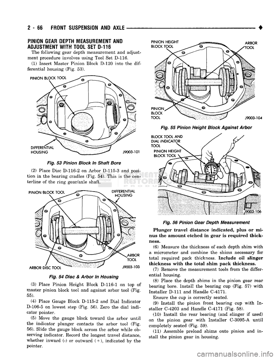
D-116 The following gear depth measurement and adjust
ment procedure involves using Tool Set D-116. (1) Insert Master Pinion Block D-120 into the
dif
ferential housing (Fig. 53).
Fig.
53
Pinion
Block
In Shaft
Bore
(2) Place Disc D-116-2 on Arbor D-115-3 and posi
tion in the bearing cradles (Fig. 54). This is the cen
terline of the ring gear/axle shaft.
Fig.
54
Disc
&
Arbor
In
Housing
(3) Place Pinion Height Block D-116-1 on top of
master pinion block tool and against arbor tool (Fig.
55).
(4) Place Gauge Block D-115-2 and Dial Indicator
D-106-5 on lowest step (Fig. 56). Zero the dial indi
cator pointer.
(5) Move the gauge block toward the arbor until
the indicator plunger contacts the arbor tool (Fig.
56).
Slide the gauge block across the arbor while ob
serving indicator. Record the longest travel distance,
whether inward (-) or outward
(
+ ), indicated by the
pointer.
Fig.
55
Pinion
Height
Block
Against
Arbor
Fig.
56
Pinion
Gear Depth Measurement
Plunger travel distance indicated, plus or mi
nus the amount etched in gear is required thick
ness.
(6) Measure the thickness of each depth shim with
a micrometer and combine the shims necessary for
total required pack thickness. Include oil slinger
thickness with the total shim pack thickness.
(7) Remove the measurement tools from the differ
ential housing.
(8) Place the depth shims in the pinion gear rear
bearing bore. Install the bearing cup (Fig. 57) with
Installer D-lll and Handle C-4171.
Ensure the cup is correctly seated. (9) Install the pinion front bearing cup with In
staller C-4203 and Handle C-4171 (Fig. 58). (10) Install the rear bearing (and slinger if used)
on the pinion gear with Installer C-3095-A until
completely seated (Fig. 59).
(11) Assemble preload shims onto pinion and in
stall the pinion gear in housing.
Page 121 of 1502
2
- 88
FRONT
SUSPENSION
AND
AXLE
•
TORQUE WRENCH SPECIAL TOOL
C-3281
RH418A
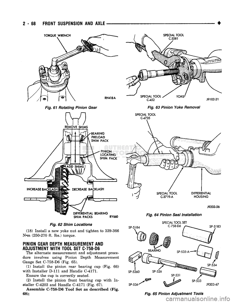
Fig.
61 Rotating
Pinion
Gear Ml
REMOVE SHIMS
BEARING PRELOAD
SHIM
PACK
PINION
LOCATING
SHIM
PACK
DIFFERENTIAL
BEARING
SHIM PACKS
RY660
Fig.
62
Shim
Locations
(18) Install a new yoke nut and tighten to 339-366
N-m (250-270 ft. lbs.) torque.
PINION
GEAR
DEPTH
MEASUREMENT
AND
ADJUSTMENT
WITH
TOOL
SET
C-758-D6
The alternate measurement and adjustment proce
dure involves using Pinion Depth Measurement Gauge Set C-758-D6 (Fig. 65). (1) Install the pinion rear bearing cup (Fig. 66)
with Installer D-lll and Handle C-4171.
Ensure the cup is correctly seated. (2) Install the pinion front bearing cup with In
staller C-4203 and Handle C-4171 (Fig. 67). Assemble C-758-D6 Tool Set as described (Fig.
68);
SPECIAL
TOOL
C-452
J9102-31
Fig.
63
Pinion
Yoke
Removal
SPECIAL
TOOL C4735
SP-5184 C-3719-A
DIFFERENTIAL
HOUSING
J9203-56
Fig.
64
Pinion
Seal
Installation
SPECIAL
TOOL
SET C-758-D6
J9203-67
Fig.
65
Pinion
Adjustment Tools
Page 147 of 1502
3
- 20
REAR SUSPENSION
AND
AXLE
•
SPECIAL
TOOL
C-4171
SPECIAL
TOOL
8-3/8-
C-4340
9.1/4-
C-4213
J9203-33
Fig.
19 Differential Bearing Installation
PINION DEPTH MEASUREMENT AND ADJUSTMENT
WITH
GAUGE SET
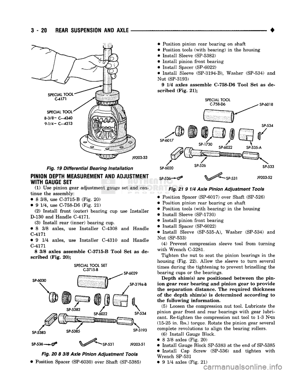
(1) Use pinion gear adjustment gauge set and con
tinue the assembly: • 8 3/8, use C-3715-B (Fig. 20)
• 9 1/4, use C-758-D6 (Fig. 21) (2) Install front (outer) bearing cup use Installer
D-130 and Handle C-4171. (3) Install rear (inner) bearing cup.
• 8 3/8 axles, use Installer C-4308 and Handle C-4171
• 9 1/4 axles, use Installer C-4310 and Handle C-4171 8 3/8 axles assemble C-3715-B Tool Set as de
scribed (Fig. 20);
SPECIAL
TOOL
SET
G3715-B
SP-6030
SP-536—
SP-531
J9203-51
Fig.
20 8 3/8 Axle
Pinion
Adjustment Tools
• Position Spacer (SP-6030) over Shaft (SP-5385) • Position pinion rear bearing on shaft
• Position tools (with bearing) in the housing
• Install Sleeve (SP-5382)
• Install pinion front bearing
• Install Spacer (SP-6022)
• Install Sleeve (SP-3194-B), Washer (SP-534) and
Nut (SP-3193) 9 1/4 axles assemble C-758-D6 Tool Set as de
scribed (Fig. 21);
SPECIAL TOOL C-758-D6
SP-6018
SP-536-*-
21 9 1/4 Axle
Pinion
Adjustment Tools and • Position Spacer (SP-6017) over Shaft (SP-526)
• Position pinion rear bearing on shaft
• Position tools (with bearing) in the housing
• Install Sleeve (SP-1730)
• Install pinion front bearing
• Install Spacer (SP-6022)
• Install Sleeve (SP-535-A), Washer (SP-534)
Nut (SP-533) (4) Prevent compression sleeve tool from turning
with Wrench C-3281.
Tighten the nut to seat the pinion bearings in the
housing (Fig. 22). Allow the sleeve to turn several
times during the tightening to prevent brinelling the
bearing cups or the bearings.
Depth shim(s) are positioned between the pin
ion gear rear bearing and pinion gear to provide the separation distance. The required thickness
of the depth shim(s) is determined according to
the following information. (5) Loosen the compression nut tool. Lubricate the
pinion gear front and rear bearings with gear lubri cant. Re-tighten the compression nut tool to 1-3 N*m (15-25 in. lbs.) torque. Rotate the pinion gear several
complete revolutions to align the bearing rollers. (6) Install Gauge Block.
• 8 3/8 axles (Fig. 20)
• Install Gauge Block SP-5383 at the end of SP-5385
• Install Cap Screw (SP-536) and tighten with
Wrench SP-531 • 9 1/4 axles (Fig. 21)