1993 DODGE TRUCK seat adjustment
[x] Cancel search: seat adjustmentPage 1133 of 1502
21 - 132
IN-VEHICLE
SERVICE-32RH/36RH/37RH/42RH/46RH
•
IDLE STOP
ADJUSTMENT
• —/
SPACER (USE
Hk±s
FEELER
GAUGES
/o)
OR SHIM STOCK)
THROTTLE BODY LEVER TRANSMISSION
THROTTLE CABLE
TORQUE
SHAFT
BRACKET.
CABLE
RETURN
SPRING
^
CABLE
CONDUIT
CABLE
^1
BUTTON
1
CABLE
\>
WIPER
J932M84
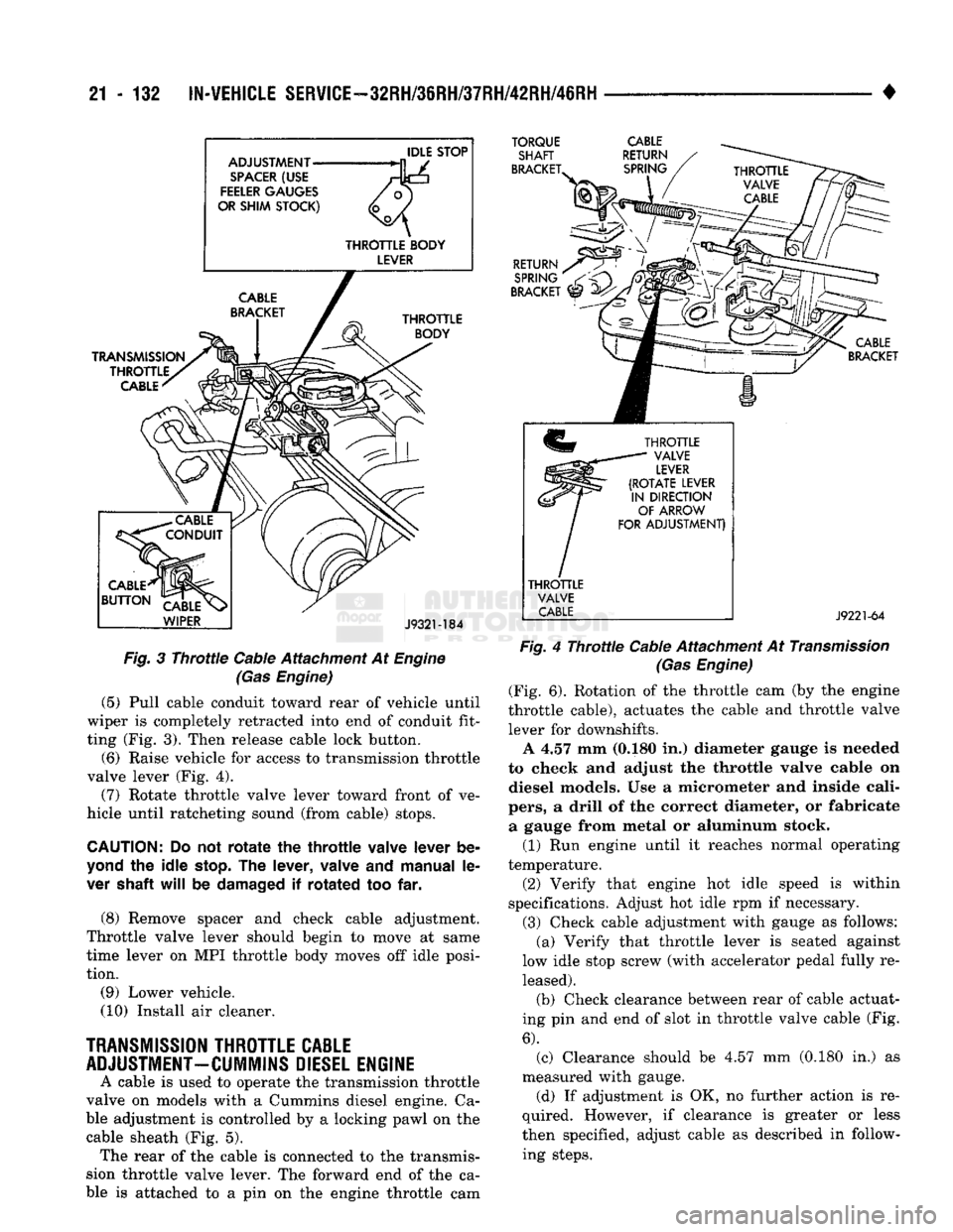
Fig.
3
Throttle
Cable Attachment At
Engine
(Gas
Engine)
(5) Pull cable conduit toward rear of vehicle until
wiper is completely retracted into end of conduit fit
ting (Fig. 3). Then release cable lock button. (6) Raise vehicle for access to transmission throttle
valve lever (Fig. 4).
(7) Rotate throttle valve lever toward front of ve
hicle until ratcheting sound (from cable) stops.
CAUTION:
Do not
rotate
the
throttle
valve
lever
be
yond
the
idle
stop.
The
lever,
valve
and
manual
le
ver
shaft
will
be
damaged
if
rotated
too far.
(8) Remove spacer and check cable adjustment.
Throttle valve lever should begin to move at same
time lever on MPI throttle body moves off idle posi
tion.
(9) Lower vehicle.
(10) Install air cleaner.
TRANSMISSION
THROTTLE
CABLE
ADJUSTMENT-CUMMINS
DIESEL
ENGINE
A cable is used to operate the transmission throttle
valve on models with a Cummins diesel engine. Ca
ble adjustment is controlled by a locking pawl on the cable sheath (Fig. 5). The rear of the cable is connected to the transmis
sion throttle valve lever. The forward end of the ca
ble is attached to a pin on the engine throttle cam
RETURN
SPRING
/
BRACKET
^
CABLE
BRACKET
THROTTLE
VALVE
LEVER
(ROTATE
LEVER
IN
DIRECTION
OF
ARROW
FOR
ADJUSTMENT)
THROTTLE
VALVE
CABLE
J9221-64
Fig.
4
Throttle
Cable Attachment At
Transmission
(Gas
Engine)
(Fig. 6). Rotation of the throttle cam (by the engine
throttle cable), actuates the cable and throttle valve lever for downshifts. A 4.57 mm (0.180 in.) diameter gauge is needed
to check and adjust the throttle valve cable on diesel models. Use a micrometer and inside cali
pers,
a drill of the correct diameter, or fabricate a gauge from metal or aluminum stock. (1) Run engine until it reaches normal operating
temperature.
(2) Verify that engine hot idle speed is within
specifications. Adjust hot idle rpm if necessary.
(3) Check cable adjustment with gauge as follows: (a) Verify that throttle lever is seated against
low idle stop screw (with accelerator pedal fully re leased).
(b) Check clearance between rear of cable actuat
ing pin and end of slot in throttle valve cable (Fig.
6).
(c) Clearance should be 4.57 mm (0.180 in.) as
measured with gauge. (d) If adjustment is OK, no further action is re
quired. However, if clearance is greater or less
then specified, adjust cable as described in follow ing steps.
Page 1135 of 1502
21
- 134
IN-WEHiCLE SER¥iCE-32RH/3IRH/37RH/42RH/46RH
• • On 36RH/37RH746RH, back off adjusting screw
two turns. (6) Hold adjusting screw in place with backup
wrench. Then tighten locknut to 34 N*m (25 ft. lbs.) torque.
(7) Position new gasket on oil pan and install pan
on transmission. Tighten pan bolts to 17 N»m (13 ft.
lbs.) torque.
(8) Lower vehicle and refill transmission with Mo
par ATF Plus, type 7176, or Dexron II™ fluid.
Fig. § Rear Band Adjustment Screw Location
SPEEDOMETER
SERVICE
Rear axle gear ratio and tire size determine speed
ometer pinion requirements. If the gear must be re
placed, refer to the parts catalogue information for
the correct pinion.
ADAPTER
AND
PINION REMOWAL
(1) Raise vehicle.
(2) Disconnect wires from vehicle speed sensor.
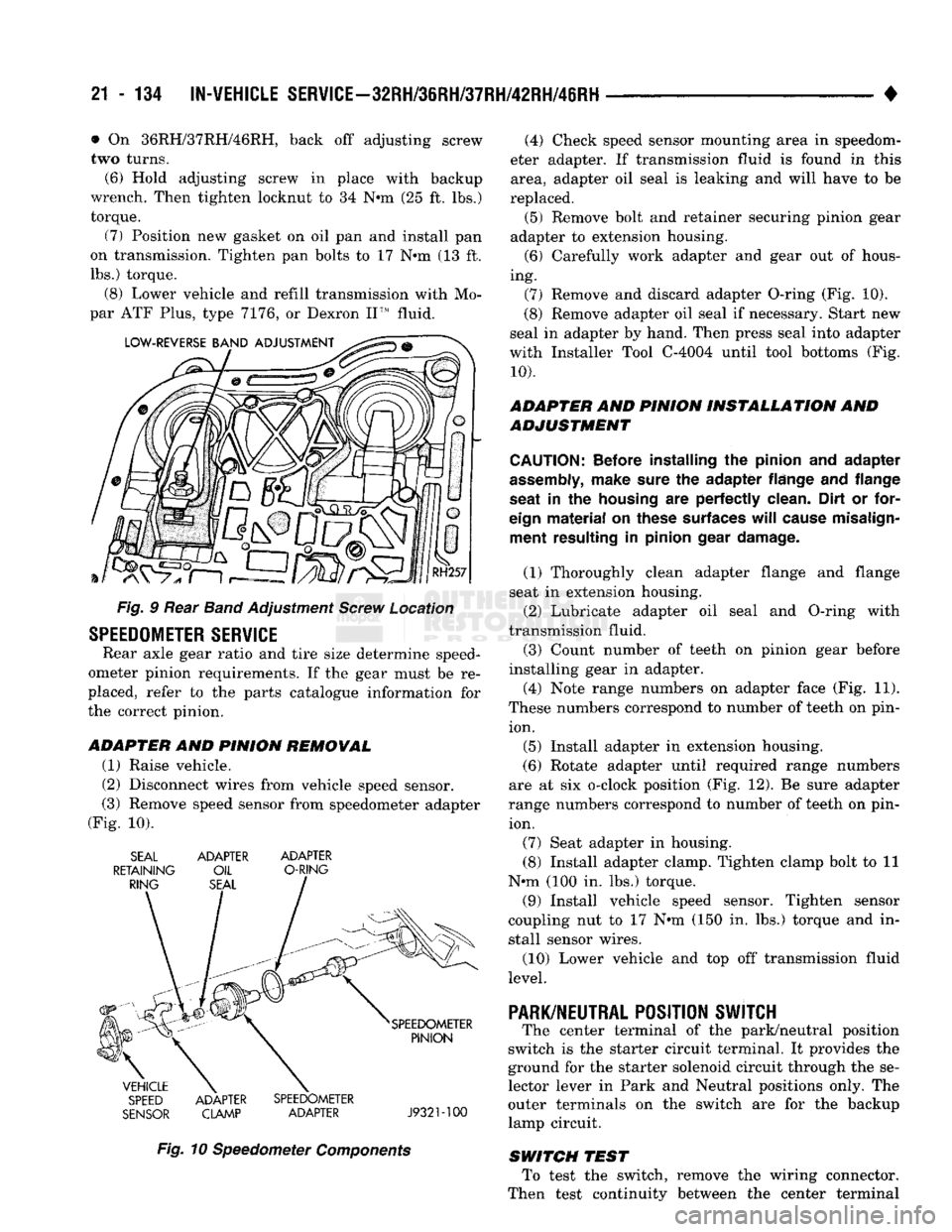
(3) Remove speed sensor from speedometer adapter
(Fig. 10). SEAL ADAPTER ADAPTER
RETAINING OIL O-RING
SPEED ADAPTER SPEEDOMETER
SENSOR CLAMP ADAPTER J932M00
Fig. 10 Speedometer Components (4) Check speed sensor mounting area in speedom
eter adapter. If transmission fluid is found in this area, adapter oil seal is leaking and will have to be
replaced. (5) Remove bolt and retainer securing pinion gear
adapter to extension housing. (6) Carefully work adapter and gear out of hous
ing. (7) Remove and discard adapter O-ring (Fig. 10).
(8) Remove adapter oil seal if necessary. Start new
seal in adapter by hand. Then press seal into adapter
with Installer Tool C-4004 until tool bottoms (Fig.
10).
ADAPTER AND PINION INSTALLATION AND
ADJUSTMENT
CAUTION:
Before installing
the
pinion
and
adapter
assembly,
make sure
the
adapter flange
and
flange
seat
in the
housing
are
perfectly clean. Dirt
or
for
eign
material
on
these surfaces
will
cause misalign ment resulting
in
pinion gear damage.
(1) Thoroughly clean adapter flange and flange
seat in extension housing.
(2) Lubricate adapter oil seal and O-ring with
transmission fluid.
(3) Count number of teeth on pinion gear before
installing gear in adapter.
(4) Note range numbers on adapter face (Fig. 11).
These numbers correspond to number of teeth on pin ion.
(5) Install adapter in extension housing.
(6) Rotate adapter until required range numbers
are at six o-clock position (Fig. 12). Be sure adapter
range numbers correspond to number of teeth on pin ion.
(7) Seat adapter in housing.
(8) Install adapter clamp. Tighten clamp bolt to 11
N*m (100 in. lbs.) torque.
(9) Install vehicle speed sensor. Tighten sensor
coupling nut to 17 N*m (150 in. lbs.) torque and in
stall sensor wires.
(10) Lower vehicle and top off transmission fluid
level.
PARK/NEUTRAL
POSITION SWJTCH
The center terminal of the park/neutral position
switch is the starter circuit terminal. It provides the
ground for the starter solenoid circuit through the se
lector lever in Park and Neutral positions only. The
outer terminals on the switch are for the backup
lamp circuit.
SWITCH TEST To test the switch, remove the wiring connector.
Then test continuity between the center terminal
Page 1184 of 1502
•
TRANSMISSION
OVERHAUL—32RH
21 - 183
MODULE
J932M23
Fig.
108 Converter
Clutch
Module
Components—32RH
(20) Insert line pressure adjusting screw in adjust
ing screw bracket (Fig. 93).
(21) Install spring on end of line pressure regula
tor valve.
(22) Install switch valve spring on tang at end of
adjusting screw bracket (Fig. 94).
(23) Position adjusting screw bracket on valve
body. Align valve springs and press bracket into
place. Install short, upper bracket screws first and long bottom screw last. Verify that valve springs and
bracket are properly aligned. Then tighten all three
bracket screws to 4 N*m (35 in. lbs.) torque.
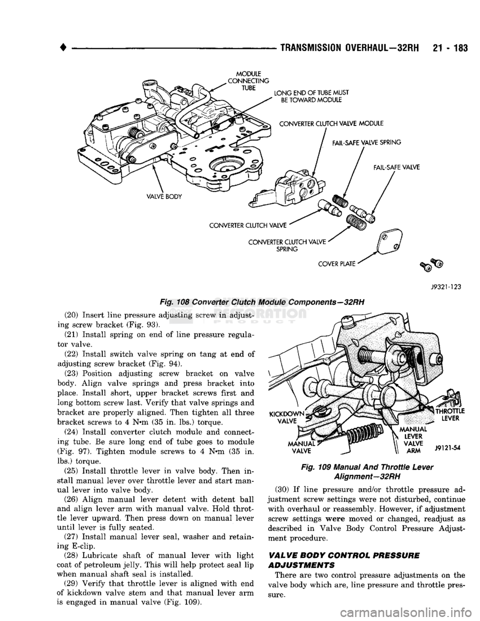
(24) Install converter clutch module and connect
ing tube. Be sure long end of tube goes to module (Fig. 97). Tighten module screws to 4 Nrn (35 in.
lbs.) torque.
(25) Install throttle lever in valve body. Then in
stall manual lever over throttle lever and start man
ual lever into valve body. (26) Align manual lever detent with detent ball
and align lever arm with manual valve. Hold throt
tle lever upward. Then press down on manual lever
until lever is fully seated. (27) Install manual lever seal, washer and retain
ing E-clip. (28) Lubricate shaft of manual lever with light
coat of petroleum jelly. This will help protect seal lip
when manual shaft seal is installed. (29) Verify that throttle lever is aligned with end
of kickdown valve stem and that manual lever arm
is engaged in manual valve (Fig. 109).
Fig.
109 Manual And
Throttle
Lever
Alignment—32RH
(30) If line pressure and/or throttle pressure ad
justment screw settings were not disturbed, continue with overhaul or reassembly. However, if adjustment screw settings were moved or changed, readjust as
described in Valve Body Control Pressure Adjust
ment procedure.
VALVE BODY CONTROL PRESSURE
ADJUSTMENTS
There are two control pressure adjustments on the
valve body which are, line pressure and throttle pres
sure.
Page 1215 of 1502
21
- 214
TRANSMISSION
OVERHAUL—3SRH/37RH
SELECTIVE
SNAP
RING
FEELER
GAUGE
RH295
Fig.
74
Measuring
Rear
Clutch
Pack
Clearance
(Typical)
PLANETARY
GEAR TRAIN AND OUTPUT SHAFT
OVERHAUL
GEARTRAIN AND
SHAFT INSPECTION
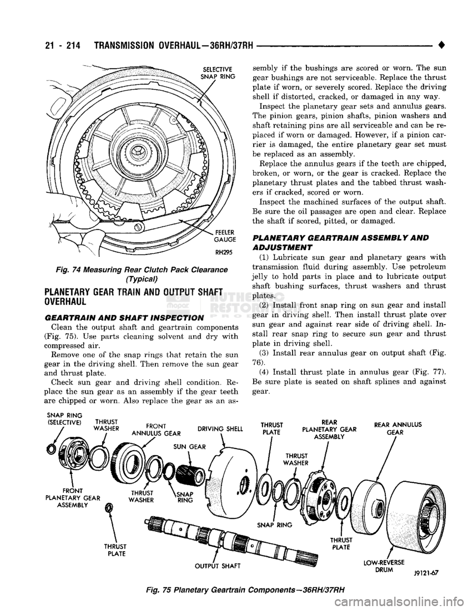
Clean the output shaft and geartrain components
(Fig. 75). Use parts cleaning solvent and dry with
compressed air.
Remove one of the snap rings that retain the sun
gear in the driving shell. Then remove the sun gear and thrust plate.
Check sun gear and driving shell condition. Re
place the sun gear as an assembly if the gear teeth are chipped or worn. Also replace the gear as an as-
SNAP
RING
(SELECTIVE)
THRUST
WASHER
FRONT
ANNULUS GEAR
sembly if the bushings are scored or worn. The sun
gear bushings are not serviceable. Replace the thrust
plate if worn, or severely scored. Replace the driving shell if distorted, cracked, or damaged in any way.
Inspect the planetary gear sets and annulus gears.
The pinion gears, pinion shafts, pinion washers and shaft retaining pins are all serviceable and can be re
placed if worn or damaged. However, if a pinion car rier is damaged, the entire planetary gear set must
be replaced as an assembly.
Replace the annulus gears if the teeth are chipped,
broken, or worn, or the gear is cracked. Replace the
planetary thrust plates and the tabbed thrust wash ers if cracked, scored or worn.
Inspect the machined surfaces of the output shaft.
Be sure the oil passages are open and clear. Replace
the shaft if scored, pitted, or damaged.
PLANETARY GEARTRAIN ASSEMBLY AND
ADJUSTMENT
(1) Lubricate sun gear and planetary gears with
transmission fluid during assembly. Use petroleum
jelly to hold parts in place and to lubricate output shaft bushing surfaces, thrust washers and thrust
plates.
(2) Install front snap ring on sun gear and install
gear in driving shell. Then install thrust plate over
sun gear and against rear side of driving shell. In stall rear snap ring to secure sun gear and thrust
plate in driving shell.
(3) Install rear annulus gear on output shaft (Fig.
76).
(4) Install thrust plate in annulus gear (Fig. 77).
Be sure plate is seated on shaft splines and against gear.
DRIVING SHELL
THRUST
PLATE
REAR
PLANETARY GEAR
ASSEMBLY
REAR
ANNULUS
GEAR
FRONT
PLANETARY GEAR
ASSEMBLY
THRUST
PLATE
OUTPUT
SHAFT
LOW-REVERSE
DRUM
J9121-67
Fig.
75 Planetary
Geartrain
Components—36RH/37RH
Page 1224 of 1502
•
TRANSMISSION
OVERHAUL—36RH/37RH
21 - 223 (16) Align and install governor plug end plate
(Fig. 99) on valve body and install end plate screws.
Tighten screws to 4 N»m (35 in. lbs.) torque.
(17) Install manual valve (Fig. 99). (18) Install throttle valve and spring. Then install
kickdown valve and detent (Fig. 99). (19) Install pressure regulator valve and switch
valve (Fig. 99).
(20) Install manual lever detent spring in housing.
Place detent ball on end of spring and push ball and spring into housing. Secure ball and spring with Re
tainer Tool 6583 (Fig. 88).
(21) Insert line pressure adjusting screw in adjust
ing screw bracket (Fig. 92).
(22) Place valve spring on end of line pressure reg
ulator valve.
(23) Install switch valve spring on tang at end of
adjusting screw bracket (Fig. 87). (24) Install adjusting screw bracket on valve body.
Align springs, press bracket toward valve body and install long bottom bracket attaching screw first. Do
not tighten screw fully at this time.
(25) Carefully align bracket on valve body and
transfer plate and install remaining (two) bracket screws. Verify that valve springs and bracket are
properly aligned. Then tighten all three bracket screws to 4 N*m (35 in. lbs.) torque.
(26) Install throttle lever in valve body. Then in
stall manual lever over throttle lever and start man
ual lever into valve body.
(27) Align manual lever detent with detent ball
and align lever arm with manual valve. Hold throt
tle lever upward. Then press down on manual lever until lever is fully seated.
(28) Install manual lever seal, washer and retain
ing E-clip.
(29) Lubricate shaft of manual lever with light
coat of petroleum jelly. This will help protect seal lip
when manual shaft seal is installed.
(30) Verify that throttle lever is aligned with end
of kickdown valve stem and that manual lever arm
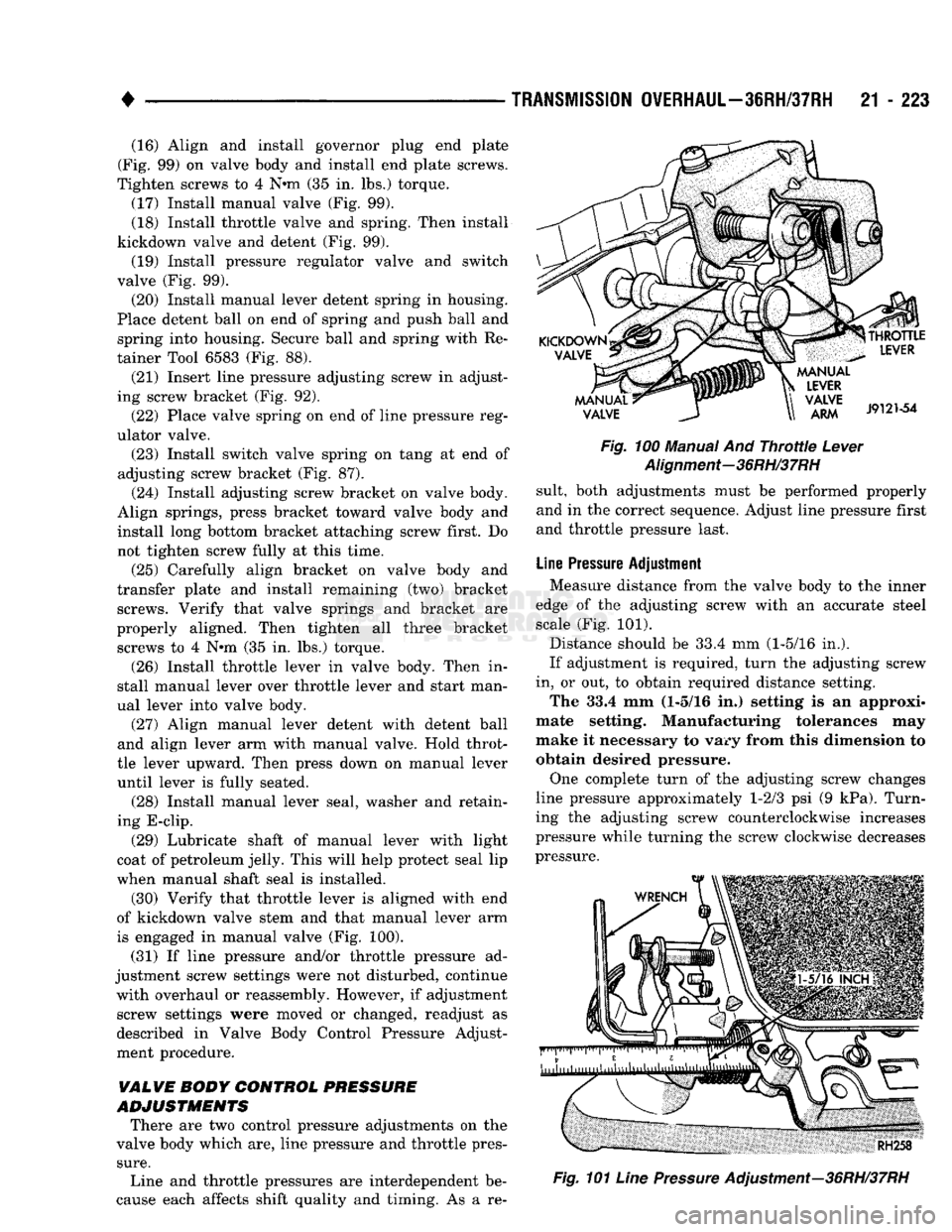
is engaged in manual valve (Fig. 100).
(31) If line pressure and/or throttle pressure ad
justment screw settings were not disturbed, continue with overhaul or reassembly. However, if adjustment screw settings were moved or changed, readjust as
described in Valve Body Control Pressure Adjust
ment procedure.
VALVE BODY CONTROL
PRESSURE
ADJUSTMENTS
There are two control pressure adjustments on the
valve body which are, line pressure and throttle pres
sure.
Line and throttle pressures are interdependent be
cause each affects shift quality and timing. As a re-
Fig.
100 Manual And
Throttle
Lever
Alignment-36RH/37RH
suit, both adjustments must be performed properly
and in the correct sequence. Adjust line pressure first
and throttle pressure last.
Line
Pressure
Adjustment Measure distance from the valve body to the inner
edge of the adjusting screw with an accurate steel scale (Fig. 101).
Distance should be 33.4 mm (1-5/16 in.).
If adjustment is required, turn the adjusting screw
in, or out, to obtain required distance setting. The 33.4 mm (1-5/16 in.) setting is an approxi
mate setting. Manufacturing tolerances may
make it necessary to vary from this dimension to obtain desired pressure.
One complete turn of the adjusting screw changes
line pressure approximately 1-2/3 psi (9 kPa). Turn
ing the adjusting screw counterclockwise increases
pressure while turning the screw clockwise decreases
pressure.
Fig.
101
Line
Pressure
Adjustment—36RH/37RH
Page 1225 of 1502
21
- 224
TRANSMISSION
OVERHAUL—36RH/37RH
• Throttle
Pressure
Adjustment
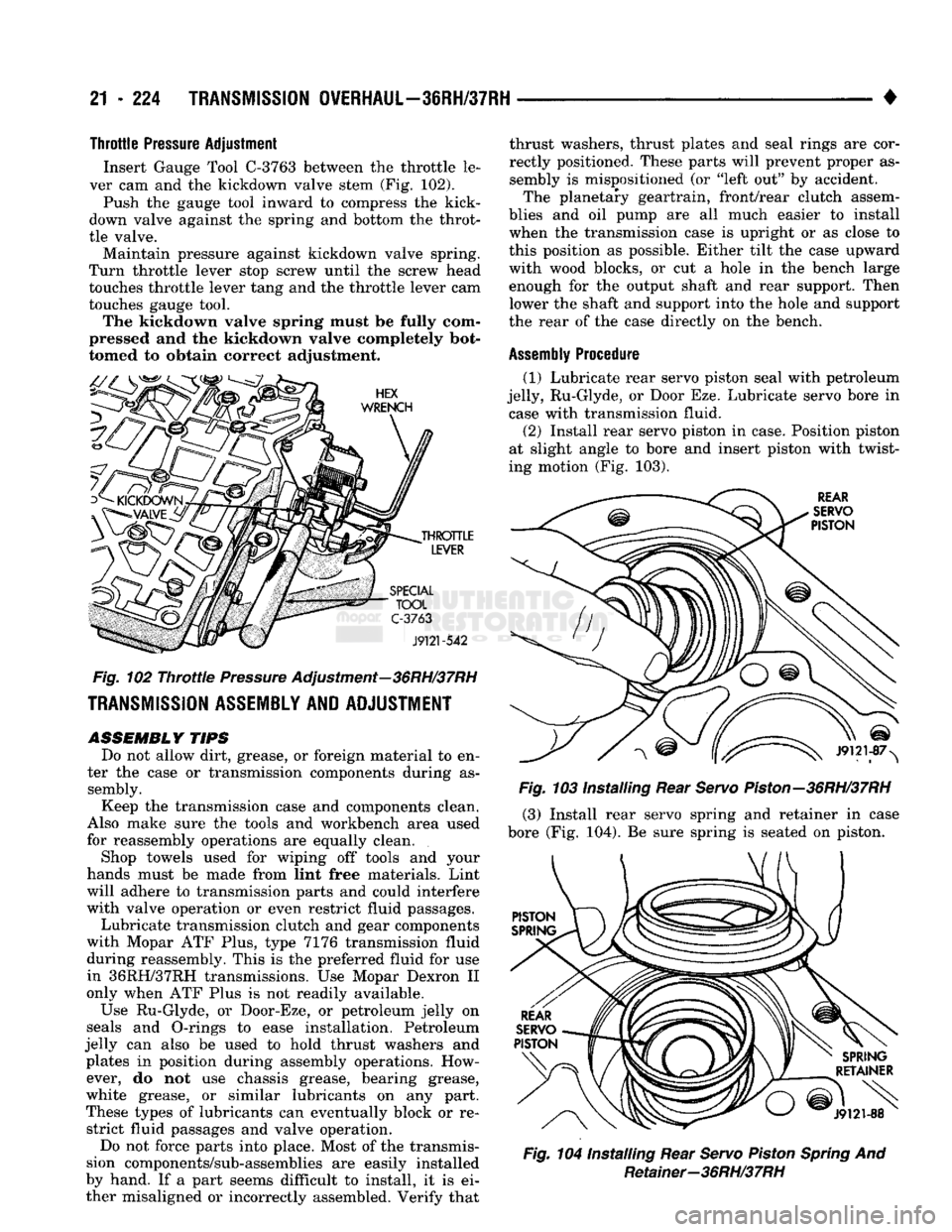
Insert Gauge Tool
C-3763
between the throttle le
ver cam and the kickdown valve stem (Fig. 102).
Push the gauge tool inward to compress the kick-
down valve against the spring and bottom the throt
tle valve. Maintain pressure against kickdown valve spring.
Turn throttle lever stop screw until the screw head
touches throttle lever tang and the throttle lever cam
touches gauge tool. The kickdown valve spring must be fully com
pressed and the kickdown valve completely bot
tomed to obtain correct adjustment.
HEX
WRENCH
THROTTLE
LEVER
SPECIAL
TOOL
C-3763
J9121-542
Fig.
102
Throttle
Pressure
Adjustment—36RH/37RH
TRANSMISSION
ASSEMBLY
AND
ADJUSTMENT
ASSEMBLY
TIPS
Do not allow dirt, grease, or foreign material to en
ter the case or transmission components during as sembly.
Keep the transmission case and components clean.
Also make sure the tools and workbench area used
for reassembly operations are equally clean.
Shop towels used for wiping off tools and your
hands must be made from lint free materials. Lint
will adhere to transmission parts and could interfere
with valve operation or even restrict fluid passages.
Lubricate transmission clutch and gear components
with Mopar ATF Plus, type 7176 transmission fluid
during reassembly. This is the preferred fluid for use in 36RH/37RH transmissions. Use Mopar Dexron II
only when ATF Plus is not readily available.
Use Ru-Glyde, or Door-Eze, or petroleum jelly on
seals and O-rings to ease installation. Petroleum
jelly can also be used to hold thrust washers and plates in position during assembly operations. However, do not use chassis grease, bearing grease,
white grease, or similar lubricants on any part.
These types of lubricants can eventually block or re strict fluid passages and valve operation.
Do not force parts into place. Most of the transmis
sion components/sub-assemblies are easily installed
by hand. If a part seems difficult to install, it is ei ther misaligned or incorrectly assembled. Verify that thrust washers, thrust plates and seal rings are cor
rectly positioned. These parts will prevent proper as
sembly is mispositioned (or "left out" by accident. The planetary geartrain, front/rear clutch assem
blies and oil pump are all much easier to install
when the transmission case is upright or as close to
this position as possible. Either tilt the case upward
with wood blocks, or cut a hole in the bench large enough for the output shaft and rear support. Then lower the shaft and support into the hole and support
the rear of the case directly on the bench.
Assembly
Procedure
(1) Lubricate rear servo piston seal with petroleum
jelly, Ru-Glyde, or Door Eze. Lubricate servo bore in case with transmission fluid. (2) Install rear servo piston in case. Position piston
at slight angle to bore and insert piston with twist
ing motion (Fig. 103).
REAR
SERVO
PISTON
J9121-87>
Fig.
103 Installing Rear
Servo
Piston—36RH/37RH
(3) Install rear servo spring and retainer in case
bore (Fig. 104). Be sure spring is seated on piston.
SPRING
RETAINER
v-'
J9121-88
Fig.
104 Installing Rear
Servo
Piston
Spring
And Retainer-36RH/37RH
Page 1269 of 1502
21
- 268
TRANSMISSION
OVERHAUL-42RH
SOLENOID
CASE
CONNECTOR
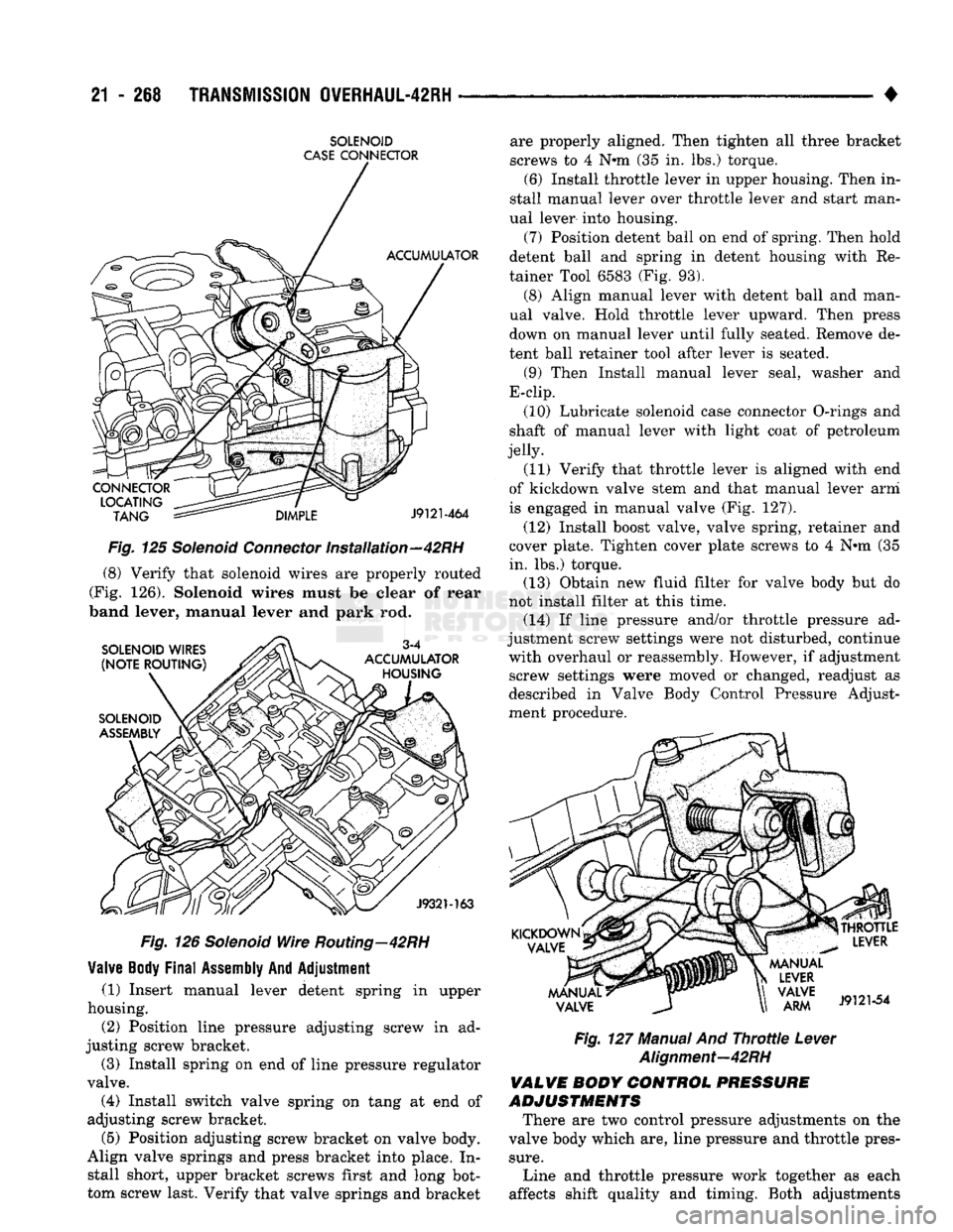
Fig. 125 Solenoid Connector Installation—42RH (8) Verify that solenoid wires are properly routed
(Fig. 126). Solenoid wires must be clear of rear
band lever, manual lever and
park
rod.
Fig, 126 Solenoid Wire Routing—42RH
Valve
Body
Final
Assembly
And
Adjustment
(1) Insert manual lever detent spring in upper
housing. (2) Position line pressure adjusting screw in ad
justing screw bracket.
(3) Install spring on end of line pressure regulator
valve. (4) Install switch valve spring on tang at end of
adjusting screw bracket.
(5) Position adjusting screw bracket on valve body.
Align valve springs and press bracket into place. In stall short, upper bracket screws first and long bot
tom screw last. Verify that valve springs and bracket _ . . _ +
Fig. 127 Manual And Throttle Lever
Alignment-42RH
VALVE
BODY CONTROL PRESSURE
ADJUSTMENTS
There are two control pressure adjustments on the
valve body which are, line pressure and throttle pres
sure.
Line and throttle pressure work together as each
affects shift quality and timing. Both adjustments are properly aligned. Then tighten all three bracket
screws to 4 N*m (35 in. lbs.) torque.
(6) Install throttle lever in upper housing. Then in
stall manual lever over throttle lever and start man
ual lever into housing.
(7) Position detent ball on end of spring. Then hold
detent ball and spring in detent housing with Re
tainer Tool 6583 (Fig. 93).
(8) Align manual lever with detent ball and man
ual valve. Hold throttle lever upward. Then press down on manual lever until fully seated. Remove de
tent ball retainer tool after lever is seated.
(9) Then Install manual lever seal, washer and
E-clip.
(10) Lubricate solenoid case connector O-rings and
shaft of manual lever with light coat of petroleum
jelly.
(11) Verify that throttle lever is aligned with end
of kickdown valve stem and that manual lever arm
is engaged in manual valve (Fig. 127).
(12) Install boost valve, valve spring, retainer and
cover plate. Tighten cover plate screws to 4 N*m (35
in. lbs.) torque. (13) Obtain new fluid filter for valve body but do
not install filter at this time. (14) If line pressure and/or throttle pressure ad
justment screw settings were not disturbed, continue with overhaul or reassembly. However, if adjustment screw settings were moved or changed, readjust as
described in Valve Body Control Pressure Adjust
ment procedure.
Page 1314 of 1502
•
TRANSMISSION
OVERHAUL-46RH
21 - 313
TUBE
BRACE
UPPER
LOWER
HOUSING PORT
J932M62
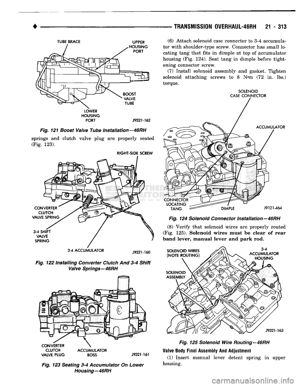
Fig.
121
Boost
Valve
Tube Installation—46RH
springs and clutch valve plug are properly seated (Fig. 123).
RIGHT-SIDE
SCREW
3-4 ACCUMULATOR
Fig.
122 Installing Converter
Clutch
And 3-4 Shift
Valve
Springs—46RH
CLUTCH ACCUMULATOR
VALVE PLUG
BOSS
J9321-161
Fig.
123 Seating 3-4
Accumulator
On
Lower
Housing—46RH
(6) Attach solenoid case connector to 3-4 accumula
tor with shoulder-type screw. Connector has small lo
cating tang that fits in dimple at top of accumulator
housing (Fig. 124). Seat tang in dimple before tight ening connector screw.
(7) Install solenoid assembly and gasket. Tighten
solenoid attaching screws to 8 N*m (72 in. lbs.)
torque.
SOLENOID
CASE
CONNECTOR
Fig.
124
Solenoid
Connector
Installation—46RH
(8) Verify that solenoid wires are properly routed
(Fig. 125). Solenoid wires must be clear of rear
band lever, manual lever and park rod.
Fig.
125
Solenoid
Wire
Routing—46RH
Valve
Body
Final
Assembly
And
Adjustment
(1) Insert manual lever detent spring in upper
housing.