1993 DODGE TRUCK service reset
[x] Cancel search: service resetPage 254 of 1502
CLUTCH
6 - 1
CLUTCH
CONTENTS
page
CLUTCH
DIAGNOSIS
2
CLUTCH
COMPONENTS
MECHANICAL COMPONENTS
The clutch mechanism
in
AD
models with
a gas or
diesel engine consists
of a
single, dry-type clutch disc and
a
diaphragm style clutch cover.
A
hydraulic
linkage
is
used
to
engage/disengage
the
clutch disc
and cover.
The transmission input shaft
is
supported
in the
crankshaft
by a
bearing.
A
sleeve type release bear
ing
is
used
to
operate
the
clutch cover pressure plate.
The release bearing
is
operated
by a
release fork
in
the clutch housing.
The
fork pivots
on a
ball stud
mounted inside
the
housing.
The
release fork
is
actu ated
by a
hydraulic slave cylinder mounted
in the
housing.
The
slave cylinder
is
operated
by a
clutch master cylinder mounted
on the
dash panel.
The
cyl
inder push
rod is
connected
to the
clutch pedal.
The clutch disc
has
cushion springs
in the
disc
hub.
The clutch disc facing
is
riveted
to the hub. The
fac ing
is
made from
a
non-asbestos material.
The
clutch
cover pressure plate
is a
diaphragm type with
a one-
piece spring
and
multiple release fingers.
The
pres sure plate release fingers
are
preset during
manufacture
and are not
adjustable.
A
265 mm
clutch disc
and
cover
are
used
in
models
with
a 3.9L
engine.
A 280 mm
clutch disc
and
cover are used
in
models with
a 5.2L, or
5.9L engine.
A
330 mm
clutch disc
and
cover
are
used
in
models
equipped with
the
optional
5.9L
Cummins diesel
en
gine.
Some diesel models
are
also equipped with
a
clutch pedal interlock switch.
The
switch
is in
circuit
with
the
starter relay
and is
actuated
by the
clutch
pedal
and
push
rod. The
clutch pedal must
be
fully depressed
in
order
to
start
the
engine.
HYDRAULIC LINKAGE COMPONENTS
The hydraulic linkage consists
of a
remote reser
voir, clutch master cylinder, clutch slave cylinder and interconnecting fluid lines.
The clutch master cylinder
is
connected
to the
clutch pedal
and the
slave cylinder
is
connected
to
the clutch release fork.
The
master cylinder
is
mounted
on the
drivers' side
of the
dash panel adja
cent
to the
brake master cylinder.
page
CLUTCH
SERVICE
11
CLUTCH LINKAGE FLUID
The clutch fluid reservoir, master cylinder, slave
cylinder
and
fluid lines
are
prefilled with fluid
at the
factory during assembly operations. The hydraulic system should
not
require additional
fluid under normal circumstances.
In
fact,
the
reser
voir fluid level will actually increase
as
normal clutch wear occurs.
For
this reason,
it is
impor
tant
to
avoid overfilling,
or
removing fluid from
the reservoir. If inspection
or
diagnosis indicates additional fluid
may
be
needed,
use
Mopar brake fluid,
or an
equiv
alent meeting
SAE and DOT
standards J1703
and
DOT
3. Do not use any
other type
of
fluid.
CLUTCH
COMPONENT LUBRICATION
Proper clutch component lubrication
is
important
to satisfactory operation.
The
correct lubricant
and
not overlubricating
are
equally important. Apply rec
ommended lubricant sparingly
to
avoid disc
and
pres sure plate contamination. Clutch
and
transmission components requiring
lu
brication
are:
• pilot bearing
• release lever pivot ball stud
• release lever contact surfaces
• clutch disc
hub
splines
• clutch pedal pivot shaft bore
• clutch pedal bushings
• input shaft splines
• input shaft pilot
hub
• transmission front bearing retainer slide surface Do
not
apply grease
to any
part
of the
clutch
cover,
or
disc.
RECOMMENDED LUBRICANTS
Use Mopar multi-purpose grease
for the
clutch
pedal bushings
and
pivot shaft.
Use
Mopar high tem
perature grease
(or
equivalent)
for all
other lubrica
tion requirements. Apply recommended amounts
and
do
not
over lubricate.
Page 383 of 1502
8E
- 2
INSTRUMENT PANEL
AND
GAUGES
•
TEMPERATURE AND
OIL
INDICATING SYSTEM
(FIG.
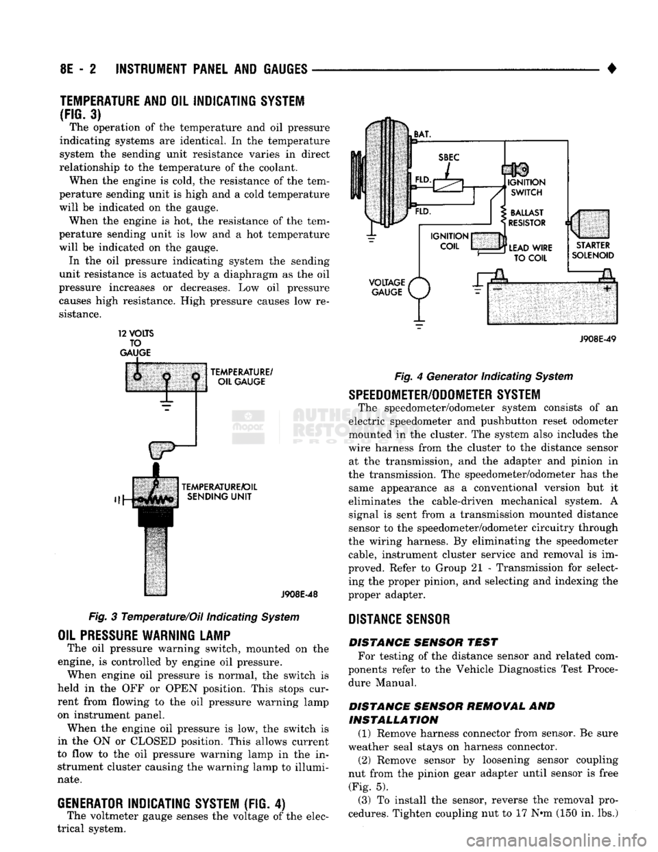
3) The operation of the temperature and oil pressure
indicating systems are identical. In the temperature
system the sending unit resistance varies in direct
relationship to the temperature of the coolant. When the engine is cold, the resistance of the tem
perature sending unit is high and a cold temperature
will be indicated on the gauge. When the engine is hot, the resistance of the tem
perature sending unit is low and a hot temperature
will be indicated on the gauge. In the oil pressure indicating system the sending
unit resistance is actuated by a diaphragm as the oil
pressure increases or decreases. Low oil pressure causes high resistance. High pressure causes low re
sistance. 12
VOLTS
TO
GAUGE
TEMPERATURE/
OIL GAUGE
TEMPERATURE/OIL SENDING
UNIT
J908E-48
Fig. 3 Temperature/Oil indicating System
OIL
PRESSURE
WARNING LAMP
The oil pressure warning switch, mounted on the
engine, is controlled by engine oil pressure. When engine oil pressure is normal, the switch is
held in the OFF or OPEN position. This stops cur
rent from flowing to the oil pressure warning lamp
on instrument panel. When the engine oil pressure is low, the switch is
in the ON or CLOSED position. This allows current
to flow to the oil pressure warning lamp in the in strument cluster causing the warning lamp to illumi
nate.
GENERATOR
INDICATING
SYSTEM
(FIG. 4)
The voltmeter gauge senses the voltage of the elec
trical system.
VOLTAGE
/*
GAUGE
P/
J908E-49 Fig. 4 Generator Indicating System
SPEEDOMETER/ODOMETER SYSTEM
The speedometer/odometer system consists of an
electric speedometer and pushbutton reset odometer
mounted in the cluster. The system also includes the
wire harness from the cluster to the distance sensor at the transmission, and the adapter and pinion in
the transmission. The speedometer/odometer has the same appearance as a conventional version but it
eliminates the cable-driven mechanical system. A signal is sent from a transmission mounted distance
sensor to the speedometer/odometer circuitry through
the wiring harness. By eliminating the speedometer cable, instrument cluster service and removal is im
proved. Refer to Group 21 - Transmission for select ing the proper pinion, and selecting and indexing the
proper adapter.
DISTANCE
SENSOR
DISTANCE SENSOR TEST For testing of the distance sensor and related com
ponents refer to the Vehicle Diagnostics Test Proce dure Manual.
DISTANCE SENSOR REMOVAL AND INSTALLATION (1) Remove harness connector from sensor. Be sure
weather seal stays on harness connector. (2) Remove sensor by loosening sensor coupling
nut from the pinion gear adapter until sensor is free (Fig. 5).
(3) To install the sensor, reverse the removal pro
cedures. Tighten coupling nut to 17 N»m (150 in. lbs.)
Page 461 of 1502
8P
- 2 POWER DOOR LOCKS
• SERVICE PROCEDURES
DOOR LOCK MOTOR REPLACEMENT
REMOVAL
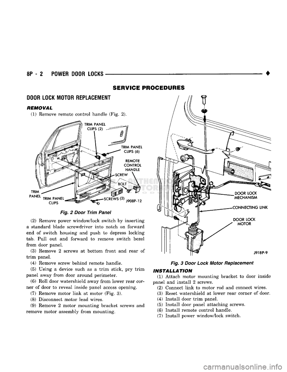
(1) Remove remote control handle (Fig. 2).
TRIM
PANEL
TRIM
PANEL
CLIPS
(6)
REMOTE
CONTROL
HANDLE
SCREW
TRIM
PANEL
CLIPS
J908P-12
Fig.
2
Door
Trim
Panel
(2) Remove power window/lock switch by inserting
a standard blade screwdriver into notch on forward
end of switch housing and push to depress locking
tab.
Pull out and forward to remove switch bezel
from door panel.
(3) Remove 2 screws at bottom front and rear of
trim panel.
(4) Remove screw behind remote handle.
(5) Using a device such as a trim stick, pry trim
panel away from door around perimeter.
(6) Roll door watershield away from lower rear cor
ner of door to reveal inside panel access opening.
(7) Remove motor link at motor (Fig. 3).
(8) Disconnect motor lead wires.
(9) Remove 2 motor mounting bracket screws and
remove motor assembly from mounting.
DOOR
LOCK
MOTOR
J918P-9
Fig.
3
Door
Lock
Motor Replacement
INSTALLATION
(1) Attach motor mounting bracket to door inside
panel and install 2 screws. (2) Connect link to motor rod and connect wires.
(3) Reset watershield at lower rear corner of door.
(4) Install door trim panel. (5) Install door panel attaching screws.
(6) Install remote control handle.
(7) Install power window/lock switch.
Page 1106 of 1502
•
AUTOMATIC
TRANSMISSION—32RH/36RH/37RH/42RH/46RH
21-105 Condition
Possible
Co
use
Correction
NO
3-4 UPSHIFT
1.
Fourth
gear overdrive
switch
(on dash) in
OFF
1.
Turn control
switch
to ON position
2.
position
Overdrive
circuit
fuse
blown
2. Replace fuse; determine why fuse failed
and
repair as necessary
(i.e.,
shorts,
grounds
in
circuit)
3.
Fourth
gear
overdrive
switch
shorted, open,
wires
loose 3. Replace switch if shorted or open and
repair loose or damaged wires
4. Overdrive solenoid or circuit
wire
loose,
shorted, open 4. Check wires/connections
with
12V test lamp
and
voltmeter; repair damaged or loose
wires/connections as necessary
5. Solenoid
feed
orifice
in valve body is
blocked
5. Remove, disassemble, clean valve body
thoroughly
6.
Fourth
gear
overdrive
solenoid
failure
6. Verify solenoid
failure
with
test lamp and
replace solenoid
7.
Sensor
failure
(vehicle speed sensor or coolant
sensor)
7. Test both
sensors
with
test lamp or volt/
ohmmeter and replace
faulty
sensor
8. Park/neutral switch open or
shorted
or
switch
wire
to
powertrain
control
module is damaged
(loss
of park/neutral
input)
8. Test switch as described in service section
and
replace if necessary
9.
Powertrain
control module
faulty
9. Check
with
DRB II
scan
tool and replace if
necessary
10.
T.P.S.
fault
10. Adjust or replace
T.P.S.
11.
Transmission fluid
temperature
sensor
fault
(if equipped)
12. Overdrive piston seal
failure
13. Wrong
overdrive
piston
spacer
11.
Replace sensor
12. Replace both
seals
13. Remove unit, check end play, and install correct spacer
14.
Low
hydraulic pressure 14. Pressure test transmission to determine
cause
15. Set-reset module
faulty
15. Replace module (if equipped)
SUPS
IN
OVERDRIVE
FOURTH
GEAR
1.
2. Low
fluid
level
Overdrive piston or seal
malfunction
1.
Add fluid and check for leaks
2. Remove overdrive unit; replace piston
seals
if worn; replace piston if damaged, if piston
retainer
is damaged, it
will
be necessary to
remove and disassemble the transmission
3. Overdrive clutch pack
worn
3. Remove overdrive unit and rebuild clutch pack
4. 3-4
shift
valve,
timing
valve, or accumulator
malfunction
4. Remove and overhaul valve body. Replace
accumulator
seals.
Make sure all valves operate
freely
in bores, and do not bind or stick. Make
sure
valve body screws are correctly tightened
and
separator plates are properly positioned
5. Overdrive
piston
retainer
bleed
orifice
blown out 5. Disassemble transmission, remove
retainer,
and
replace orifice
6. Overdrive
unit
thrust
bearing
failure
6. Disassemble overdrive unit and replace
thrust bearing (No. 1 thrust bearing is between overdrive piston and clutch hub;
No.
2 thrust bearing is between the
planetary gear and the direct clutch spring plate; No. 3
thrust
bearing is between
overrunning clutch hub and output shaft)
J9321-252
42RH/46RH OVERDRIVE DIAGNOSIS
Page 1478 of 1502
•
EMISSION
CONTROL
SYSTEMS
25
- 1
CONTENTS
page page
AIR INJECTION
SYSTEM-o
9L
HDC-GAS EVAPORATIVE EMISSION CONTROLS
6
ENGINE
15
EXHAUST EMISSION CONTROLS
10
COMPONENT
REMOVAL/INSTALLATION
17
GENERAL INFORMATION
1
GENERAL
INFORMATION
Throughout this group, references are made
to
par
ticular vehicle models
by
alphabetical designation
or
by the particular vehicle nameplate.
A
chart showing a breakdown
of
alphabetical designations
is
included
in
the
Introduction section
at
the
beginning
of
this
manual.
The 5.9L (V-8) gas powered engine will
be
referred
to
in
this group
as
either the: LDC (Light Duty Cy cle)
or
HDC (Heavy Duty Cycle) engine.
The
HDC
engine can
be
easily identified
by
the
use
of
an en
gine mounted
air
injection pump. The 3.9L/5.2L/5.9L
LDC engine will not use
an
air
injection pump.
Maintenance requirements for LDC and HDC emis
sion systems differ because
of
different load
and
op
erating conditions. This section will cover emission control systems
for
the 3.9L (V-6), 5.2L (V-8), 5.9L LDC (V-8), 5.9L HDC (V-8) and 5.9L (in-line six cylinder) diesel engines.
SERVICE
REMINDER INDICATOR
(SRI)
LIGHT
The instrument panel mounted SRI light was for
merly referred
to as the
emission maintenance
re
minder (EMR) light.
It is
used with 5.9L HDC-gas
powered engines only.
It is
not
used with diesel
en
gines.
The SRI system
is
incorporated into the powertrain
control module (PCM)
(the
PCM
was
formerly
re
ferred
to as the
engine controller
or
SBEC).
The
PCM records
the
vehicles mileage and stores
it
into
memory every
8
miles. At that time, the PCM checks
for the 60,000 and 82,500 mileage trip points. When
the current mileage matches one
of
the above men
tioned trip points,
the
SRI light
is
activated.
The following parts are
to
be replaced
at
either the
indicated mileage
or
when the SRI light remains
on
when the key
is in
the ON position. After performing
the required maintenance,
the
SRI light must
be
re set
to
turn the light
off.
96,000
km
(60,000 miles):
• Replace EGR Valve
• Clean EGR passage • Replace PCV Valve
132,000
km
(82,500 miles):
• Replace Oxygen Sensor
Refer
to
Group
0,
Lubrication and Maintenance
for
all required maintenance schedules.
Failure
to
perform
the
required maintenance
and
only reset the SRI light may be
a
violation of federal
law. Only after performing
the
required mainte
nance, should the SRI light
be
reset.
RESETTING
SRI
LIGHT
(1) Connect
the
DRB
II
scan tool
to
the
data link
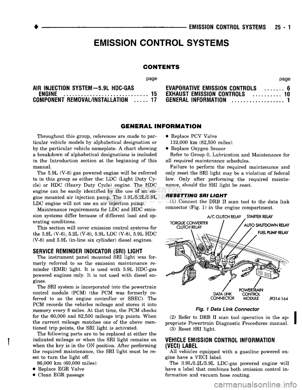
connector (Fig.
1)
in
the engine compartment.
TORQUE CONVERTER
CLUTCH RELAY
A/C
CLUTCH RELAY
.
STARTER RELAY
AUTO
SHUTDOWN RELAY FUEL PUMP RELAY DATA LINK
CONNECTOR POWERTRAIN
CONTROL
MODULE
J9314-164
Fig.
1
Data
Link
Connector
(2) Refer
to
DRB
II
scan tool operation
in
the ap
propriate Powertrain Diagnostic Procedures manual. (3) Reset SRI light.
VEHICLE
EMISSION CONTROL INFORMATION
(VECI)
LABEL
All vehicles equipped with
a
gasoline powered
en
gine have
a
VECI label. The 3.9L/5.2L/5.9L LDC-gas powered engine will
have
a
label that combines both emission control
in
formation and vacuum hose routing.
EMISSION CONTROL
SYSTEMS
Page 1479 of 1502
25
- 2
EMISSION
CONTROL
SYSTEMS
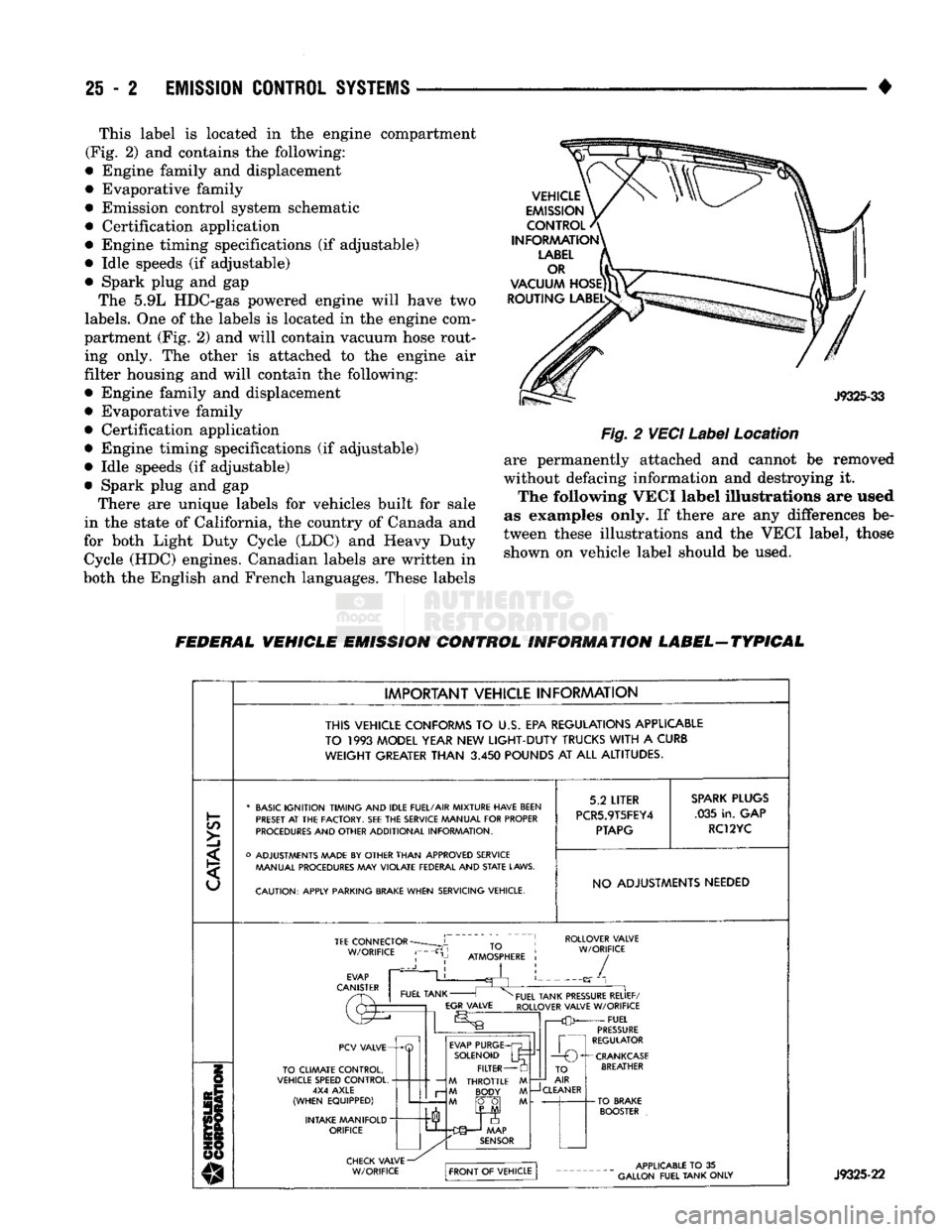
• This label is located in the engine compartment
(Fig. 2) and contains the following:
• Engine family and displacement
• Evaporative family
• Emission control system schematic
• Certification application
• Engine timing specifications (if adjustable)
• Idle speeds (if adjustable)
• Spark plug and gap The 5.9L HDC-gas powered engine will have two
labels.
One of the labels is located in the engine com
partment (Fig. 2) and will contain vacuum hose rout ing only. The other is attached to the engine air
filter housing and will contain the following:
• Engine family and displacement
• Evaporative family
• Certification application
• Engine timing specifications (if adjustable)
• Idle speeds (if adjustable)
• Spark plug and gap There are unique labels for vehicles built for sale
in the state of California, the country of Canada and
for both Light Duty Cycle (LDC) and Heavy Duty Cycle (HDC) engines. Canadian labels are written in
both the English and French languages. These labels
Fig.
2
VECI
Label
Location
are permanently attached and cannot be removed
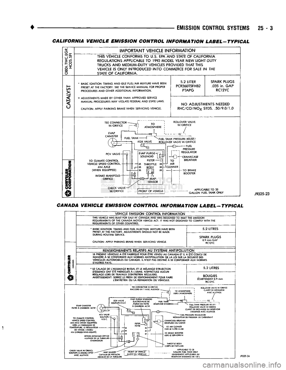
without defacing information and destroying it. The following VECI label illustrations are used
as examples only. If there are any differences be
tween these illustrations and the VECI label, those shown on vehicle label should be used.
FEDERAL VEHICLE EMISSION CONTROL INFORMATION LABEL-TYPICAL
IMPORTANT VEHICLE INFORMATION
THIS VEHICLE CONFORMS
TO U.S. EPA
REGULATIONS APPLICABLE
TO
1993
MODEL YEAR
NEW
LIGHT-DUTY
TRUCKS
WITH
A
CURB
WEIGHT
GREATER
THAN
3.450
POUNDS
AT ALL
ALTITUDES.
C/5
>]
* BASIC IGNITION TIMING AND IDLE FUEL/AIR MIXTURE HAVE BEEN
PRESET
AT THE
FACTORY.
SEE THE
SERVICE MANUAL FOR PROPER
PROCEDURES AND OTHER ADDITIONAL INFORMATION.
o ADJUSTMENTS MADE
BY
OTHER THAN APPROVED SERVICE MANUAL PROCEDURES
MAY
VIOLATE FEDERAL AND
STATE
LAWS.
CAUTION: APPLY PARKING
BRAKE
WHEN SERVICING VEHICLE. 5.2
LITER
PCR5.9T5FEY4
PTAPG
SPARK
PLUGS
.035 in. GAP
RC12YC
NO ADJUSTMENTS NEEDED TEE
CONNECTOR
W/ORIFICE ROLLOVER VALVE
W/ORIFICE
PCV VALVE-
TO CLIMATE CONTROL,
VEHICLE SPEED CONTROL, 4X4 AXLE
(WHEN EQUIPPED)
INTAKE MANIFOLD
"
ORIFICE EVAP PURGE
SOLENOID FILTER
M THROTTLE M M BODY M
M fO~0| M TO
AIR
—J
CLEANER
-CRANKCASE
BREATHER J9325-22
Page 1480 of 1502
EMISSION
CONTROL SYSTEMS
25 - :
CALIFORNIA VEHICLE EMISSION CONTROL INFORMATION LABEL-TYPICAL
or,
o_ UJ
u_
U
^
>
CO
CQ
o
IMPORTANT
VEHICLE
INFORAAATION
THIS VEHICLE CONFORMS
TO
U.S.
EPA AND STATE
OF
CALIFORNIA REGULATIONS APPLICABLE
TO 1993
MODEL YEAR NEW
LIGHT-DUTY
TRUCKS
AND
MEDIUM-DUTY VEHICLES PROVIDED
THAT
THIS VEHICLE
IS
ONLY INTRODUCED
INTO
COMMERCE FOR
SALE
IN THE
STATE
OF
CALIFORNIA.
*
BASIC
IGNITION TIMING
AND
IDLE FUEL/AIR
MIXTURE HAVE BEEN
PRESET
AT THE
FACTORY.
SEE THE
SERVICE MANUAL
FOR
PROPER
PROCEDURES
AND
OTHER
ADDITIONAL
INFORMATION.
o
ADJUSTMENTS MADE
BY
OTHER
THAN
APPROVED
SERVICE MANUAL PROCEDURES
MAY
VIOLATE
FEDERAL
AND
STATE
LAWS.
CAUTION:
APPLY
PARKING BRAKE
WHEN
SERVICING
VEHICLE.
5.2
LITER
PCR360T5FHB2
PTAPG
SPARK
PLUGS
.035
in.
GAP RC12YC NO ADJUSTMENTS NEEDED
RHC/CO/NOx
STDS.
.50/9.0/1.0
TEE
CONNECTOR
W/ORIFICE
TO
ATMOSPHERE
ROLLOVER
VALVE
W/ORIFICE
/
PCV
VALVE-
TO
CLIMATE
CONTROL,
VEHICLE SPEED
CONTROL,
4X4
AXLE
(WHEN
EQUIPPED)
INTAKE
MANIFOLD"
ORIFICE
—
M
r-
M
EVAP
PURGE
SOLENOID
FILTER
THROTTLE
BODY
FUEL
TANK PRESSURE
RELIEF/
ROLLOVER
VALVE
W/ORIFICE
FUEL
PRESSURE
REGULATOR
1
r—O
O^-CRANKCASE
TO
AIR
CLEANER
APPLICABLE
TO
35
GALLON
FUEL
TANK
ONLY
J9325-23
CANADA VEHICLE EMISSION CONTROL INFORMATION LABEL-ATYPICAL
VEHICLE
EMISSION
CONTROL
INFORAAATION
THIS
VEHICLE
WAS
BUILT
FOR
SALE
IN
CANADA
AND WAS
DESIGNED
TO
MEET
THE
EMISSION
REQUIREMENTS
OF THE
CANADA
MOTOR
VEHICLE
ACT.
IT
WAS NOT
DESIGNED
TO
COMPLY
WITH
THE
REQUIREMENTS
OF
OTHER
COUNTRIES.
'
BASIC
IGNITION TIMING
AND
FUEL
INJECTION
MIXTURE HAVE BEEN
PRESET
AT
THE
FACTORY.
ADJUSTMENTS
SHOULD
NOT
BE
MADE
DURING
ROUTINE
SERVICE.
CAUTION:
APPLY
PARKING BRAKE
WHEN
SERVICING
VEHICLE.
5.2
LITRES
SPARK
PLUGS
0.9
mm GAP
RC12YC
RENSEIGNEMENTS RELATIFS
AU
SYSTEME
ANTIPOLLUTION
LE
PRESENT
VEHICULE
A
ETE
FABRIQUE'
POUR ETRE
VENDU
AU
CANADA
ET
IL
A
ETE
CONCU
DE
MANIERE
A
SE
CON
FORMER
AUX
NORMES
ANTIPOLLUTION
DE LA LOI SUR LA
SECURITE
DES
VEHICULES
AUTOMOBILES
DU
CANADA.
IL
N'EST
PAS
DESTINE'
A SE
CON
FORMER
AUX
NORMES
D'AUTRES
PAYS.
*
LE
CALAGE
DE
L'ALLUMAGE
INITIAL
ET LE
MELANGE
D'INJECTION
D'ESSENCE
ONT
ETC:
PREREGLE'S
A
L'USINE.
N'EFFECTUEZ
AUCUN
REGLAGE
LORS
DE
TRAVAUX
D'ENTRETIEN
REGULIERS.
AVERTISSEMENT:
SERREZ
LE
FREIN
DE
STATIONNEMENT
POUR
FAIRE
L'ENTRETIEN
OU
LA
RE'PARATION
DU
VEHICULE.
5.2
LITRES
,
BOUGIES
ECARTEMENT
0.9 mm
RC12YC
ROLLOVER VALVE W/ORIFICE CLAPET DE DECHARGE AVEC AJUTAGE EVAP PURGE SOLENOID
E'LECTROVALVE
DE
_
FUEL TANK PURGE
DU
FILTRE RESERVOIR
D'ESSENCE
-
A CHARBON ACTIF /
TO CLIMATE CONTROL,
VEHICLE SPEED CONTROL.
4X4 AXLE (WHEN EQUIPPED)
VERS LA COWMAN DE
DE
TEMPERATURE. LE REGULATEUR DE VITESSE, LESSIEU
4X4 (LORSQU'AINSI EQUIPE')
INTAKE MANIFOLD ORIFICE AJUTAGE DE LA TUBULURE D'ADMISSION FUEL TANK PRESSURE RELIEF/
I
ROLLOVER VALVE W/ORIFICE
CLAPET DE DECHARGE
DU
RESERVOIR D'ESSENCE AVEC AJUTAGE FUEL PRESSURE REGULATOR
REGULATEUR DE PRESSION DE CARBURANT CHECK VALVE W/ORIFICE
SOUPAPE
A
DOUBLE EFFET
-
AVEC AJUTAGE AAAP SENSOR
"
CAPTEUR DE PRESSION
ABSOLUE DE LA TUBULURE THROTTLE BODY
CORPS DE PAPILLON APPLICABLE
TO
35
GALLON FUEL TANK ONLY
UNIQUEMENT APPLICABLE
AU
RESERVOIR D'ESSENCE DE
132
L