1993 DODGE TRUCK wiring
[x] Cancel search: wiringPage 3 of 1502

FOREWORD
The information contained in this service manual has been prepared for the professional automotive tech
nician involved in daily repair operations. This manual does not cover theory of operation, which is addressed in service training material. Information describing the operation and use of standard and optional equipment
is included in the Owner's Manual provided with the vehicle.
Information in this manual is divided into groups. These groups contain general information, diagnosis,
testing, adjustments, removal, installation, disassembly, and assembly procedures for the components.
The Component and System Index of this manual identifies the correct group for the component or system
to be serviced. In addition, a Service Manual Comment form is included at the rear of this manual. Use the form to provide Chrysler Corporation with your comments and suggestions.
To assist in locating a group title page, use the Group Tab Locator on the following page. The solid bar
after the group title is aligned to a solid tab on the first page of each group. The first page of the group has
a contents section that lists major topics within the group.
Tightening torques are provided as a specific value throughout this manual. This value represents the
midpoint of the acceptable engineering torque range for a given fastener application. These torque values are
intended for use in service assembly and installation procedures using the correct OEM fasteners. When re
placing fasteners, always use the same type (part number) fastener as removed.
Chrysler Corporation reserves the right to change testing procedures, specifications, diagnosis, repair
methods, or vehicle wiring at any time without prior notice or incurring obligation.
NOTE: The acronyms, terminology and nomenclature used to identify emissions related components in
this manual may have changed from prior publications. These new terms are in compliance with S.A.E.
recommended practice J1930. This terminology standard (J1930) is required to comply with the 1993 California Air Research Board (CARB) requirements.
Page 81 of 1502
2 - 28
FRONT
SUSPENSION
AND
AXLE
DISCONNECT
AXLE/SHIFT
MOTOR
DIAGNOSIS
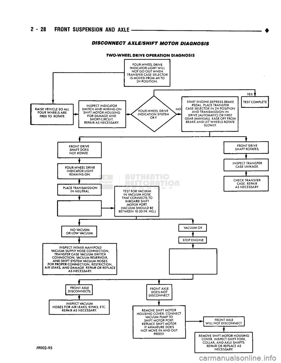
TWO-WHEEL DRIVE
OPERATION
DIAGNOSIS
FOUR-WHEEL DRIVE
INDICATOR
LIGHT
WILL NOT GO OUT WHEN
TRANSFER CASE SELECTOR
IS
MOVED FROM 4H TO 2H POSITION.
RAISE
VEHICLE SO ALL FOUR WHEELS ARE
FREE
TO ROTATE. INSPECT INDICATOR
SWITCH AND WIRING ON SHIFT MOTOR HOUSING FOR DAMAGE AND SHORT-CIRCUIT.
REPAIR
AS NECESSARY.
YES
i
START ENGINE DEPRESS BRAKE
PEDAL.
PLACE TRANSFER
CASE
SELECTOR IN 2H POSITION AND TRANSMISSION IN
DRIVE
(AUTOMATIC)
OR FIRST
GEAR
(MANUAL). EASE OFF FROM
BRAKE
AND LET WHEELS ROTATE SLOWLY. TEST COMPLETE
FRONT DRIVE SHAFT DOES
NOT ROTATE. FRONT DRIVE
SHAFT ROTATES.
FOUR-WHEEL DRIVE INDICATOR
LIGHT
REMAINS
ON. INSPECT TRANSFER
CASE
LINKAGE.
PLACE
TRANSMISSION IN NEUTRAL. TEST FOR VACUUM
IN VACUUM HOSE
THAT
CONNECTS TO INBOARD SHIFT MOTOR PORT.
(VACUUM SHOULD BE
BETWEEN 10-20 IN. HG.)
CHECK
TRANSFER
CASE.
REPAIR
AS
NECESSARY.
NO VACUUM
OR LOW VACUUM. VACUUM OK
INSPECT INTAKE MANIFOLD
VACUUM SUPPLY HOSE CONNECTION,
TRANSFER CASE VACUUM SWITCH
CONNECTION, VACUUM RESERVOIR, AND SHIFT SYSTEM VACUUM HOSES
FOR PROPER CONNECTION, RESTRICTION,
AIR LEAKS, AND DAMAGE. REPAIR OR REPLACE
AS
NECESSARY. STOP ENGINE
—r~
FRONT AXLE
DISCONNECTS.
INSPECT VACUUM
HOSES
FOR AIR LEAKS, KINKS, ETC.
REPAIR
AS NECESSARY. FRONT AXLE
DOES
NOT
DISCONNECT.
REMOVE SHIFT MOTOR
HOUSING COVER. CONNECT VACUUM PUMP TO
SHIFT MOTOR PORT.
REPLACE
SHIFT MOTOR
IF ARMATURE DOES
NOT MOVE IN AND OUT FREELY. FRONT AXLE
WILL NOT DISCONNECT.
J9002-95
REMOVE SHIFT MOTOR HOUSING
COVER. INSPECT SHIFT FORK, COLLAR, AND AXLE SHAFTS.
REPAIR
OR REPLACE AS
NECESSARY
Page 82 of 1502
FRONT
SUSPENSION AND
AXLE
2 - 29
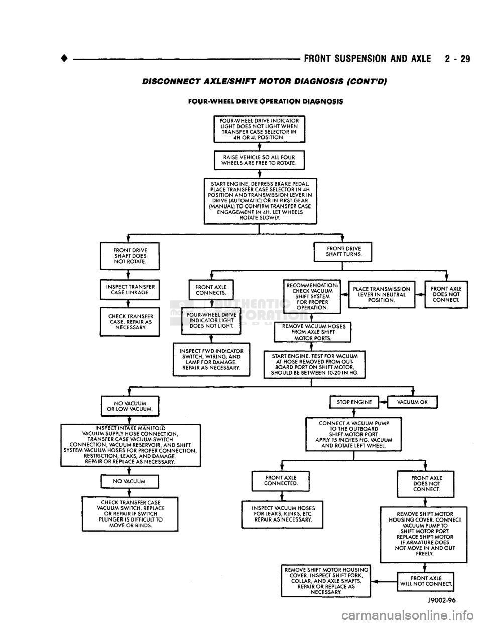
DISCONNECT AXLE/SHIFT MOTOR DIAGNOSIS
(CONT'D)
FOUR-WHEEL
DRIVE
OPERATION
DIAGNOSIS
FOUR-WHEEL DRIVE INDICATOR
LIGHT
DOES NOT
LIGHT
WHEN TRANSFER CASE SELECTOR IN 4H OR 4L POSITION.
RAISE
VEHICLE SO ALL FOUR
WHEELS ARE FREE TO ROTATE.
START ENGINE, DEPRESS BRAKE PEDAL.
PLACE
TRANSFER CASE SELECTOR IN 4H
POSITION AND TRANSMISSION LEVER IN DRIVE
(AUTOMATIC)
OR IN FIRST GEAR
(MANUAL) TO CONFIRM TRANSFER CASE ENGAGEMENT IN 4H. LET WHEELS ROTATE SLOWLY.
FRONT DRIVE SHAFT DOES
NOT ROTATE. FRONT DRIVE
SHAFT TURNS.
INSPECT TRANSFER
CASE
LINKAGE.
CHECK
TRANSFER
CASE.
REPAIR AS
NECESSARY.
FRONT AXLE
CONNECTS.
FOUR-WHEEL DRIVE INDICATOR
LIGHT
DOES
NOT LIGHT.
INSPECT FWD INDICATOR SWITCH, WIRING, AND
LAMP FOR DAMAGE.
REPAIR
AS NECESSARY. RECOMMENDATION:
CHECK
VACUUM SHIFT SYSTEM FOR PROPER
OPERATION.
PLACE
TRANSMISSION
LEVER IN NEUTRAL POSITION. FRONT AXLE
DOES
NOT
CONNECT.
REMOVE VACUUM HOSES FROM AXLE SHIFT MOTOR PORTS.
START ENGINE. TEST FOR VACUUM AT HOSE REMOVED FROM
OUT
BOARD
PORT ON SHIFT MOTOR,
SHOULD BE BETWEEN 10-20 IN HG.
NO VACUUM
OR LOW VACUUM. STOP ENGINE
H VACUUM OK
INSPECT INTAKE MANIFOLD
VACUUM SUPPLY HOSE CONNECTION, TRANSFER CASE VACUUM SWITCH
CONNECTION, VACUUM RESERVOIR, AND SHIFT
SYSTEM VACUUM HOSES FOR PROPER CONNECTION, RESTRICTION, LEAKS, AND DAMAGE.
REPAIR
OR REPLACE AS NECESSARY. CONNECT A VACUUM PUMP
TO THE OUTBOARD
SHIFT MOTOR PORT.
APPLY 15 INCHES HG. VACUUM AND ROTATE LEFT WHEEL.
NO VACUUM FRONT AXLE
CONNECTED.
CHECK
TRANSFER CASE
VACUUM SWITCH. REPLACE OR REPAIR IF SWITCH
PLUNGER IS DIFFICULT TO MOVE OR BINDS. FRONT AXLE
DOES
NOT
CONNECT.
INSPECT VACUUM HOSES FOR LEAKS, KINKS, ETC.
REPAIR
AS NECESSARY. REMOVE SHIFT MOTOR
HOUSING COVER. CONNECT VACUUM PUMP TO
SHIFT MOTOR PORT.
REPLACE
SHIFT MOTOR
IF ARMATURE DOES
NOT MOVE IN AND OUT FREELY. REMOVE SHIFT MOTOR HOUSING
COVER. INSPECT SHIFT FORK, COLLAR, AND AXLE SHAFTS.
REPAIR
OR REPLACE AS
NECESSARY.
*
REMOVE SHIFT MOTOR HOUSING
COVER. INSPECT SHIFT FORK, COLLAR, AND AXLE SHAFTS.
REPAIR
OR REPLACE AS
NECESSARY.
FRONT AXLE
WILL NOT CONNECT.
REMOVE SHIFT MOTOR HOUSING
COVER. INSPECT SHIFT FORK, COLLAR, AND AXLE SHAFTS.
REPAIR
OR REPLACE AS
NECESSARY.
FRONT AXLE
WILL NOT CONNECT.
REMOVE SHIFT MOTOR HOUSING
COVER. INSPECT SHIFT FORK, COLLAR, AND AXLE SHAFTS.
REPAIR
OR REPLACE AS
NECESSARY.
J9002-96
Page 83 of 1502
2
- 30
FRONT
SUSPENSION
AND
AXLE
• REMOVAUDISASSEMBL
Y
(1) Raise and support the vehicle.
(2) Disconnect the vacuum and wiring connector
from the shift housing. (3) Remove the shift motor housing cover, gasket
and shield from the housing.
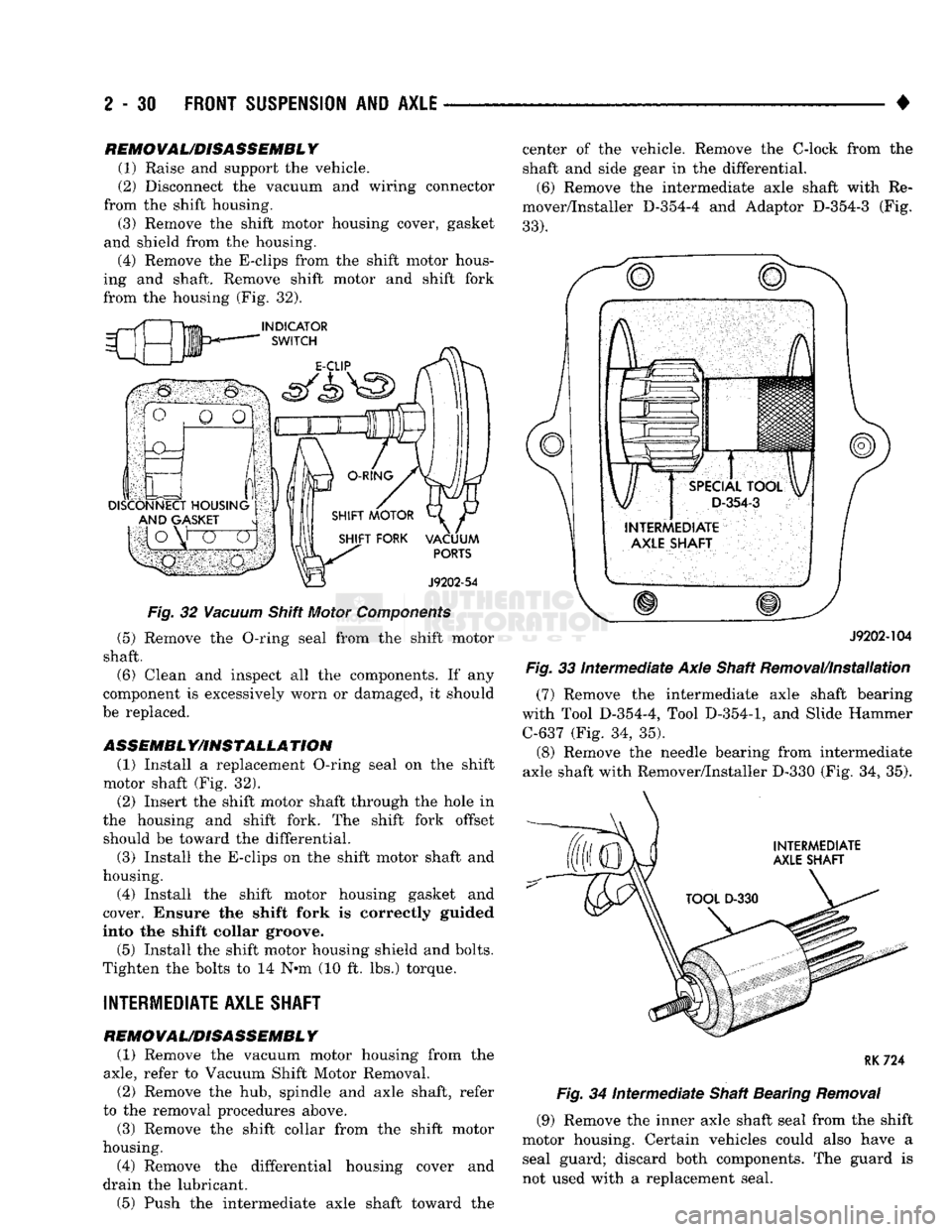
(4) Remove the E-clips from the shift motor hous
ing and shaft. Remove shift motor and shift fork
from the housing (Fig. 32).
Fig.
32
Vacuum
Shift Motor
Components
(5) Remove the O-ring seal from the shift motor
shaft. (6) Clean and inspect all the components. If any
component is excessively worn or damaged, it should
be replaced.
ASSEMBL Y/IHSTALLA TION (1) Install a replacement O-ring seal on the shift
motor shaft (Fig. 32). (2) Insert the shift motor shaft through the hole in
the housing and shift fork. The shift fork offset should be toward the differential.
(3) Install the E-clips on the shift motor shaft and
housing.
(4) Install the shift motor housing gasket and
cover. Ensure the shift fork is correctly guided
into the shift collar groove.
(5) Install the shift motor housing shield and bolts.
Tighten the bolts to 14 N*m (10 ft. lbs.) torque.
INTERMEDIATE AXLE SHAFT
REMOVAL/DISASSEMBLY (1) Remove the vacuum motor housing from the
axle,
refer to Vacuum Shift Motor Removal.
(2) Remove the hub, spindle and axle shaft, refer
to the removal procedures above.
(3) Remove the shift collar from the shift motor
housing.
(4) Remove the differential housing cover and
drain the lubricant.
(5) Push the intermediate axle shaft toward the center of the vehicle. Remove the C-lock from the
shaft and side gear in the differential.
(6) Remove the intermediate axle shaft with Re
mover/Installer D-354-4 and Adaptor D-354-3 (Fig.
33).
J9202-104
Fig.
33
intermediate
Axle Shaft Removal/Installation
(7) Remove the intermediate axle shaft bearing
with Tool D-354-4, Tool
D-354-1,
and Slide Hammer C-637 (Fig. 34, 35).
(8) Remove the needle bearing from intermediate
axle shaft with Remover/Installer D-330 (Fig. 34, 35).
RK724
Fig.
34
Intermediate
Shaft Bearing
Removal
(9) Remove the inner axle shaft seal from the shift
motor housing. Certain vehicles could also have a
seal guard; discard both components. The guard is
not used with a replacement seal.
Page 85 of 1502
2
- 32
FRONT
SUSPENSION
AND
AXLE
• (5) Disconnect flexible brake fluid hose fittings at
the frame crossmember. Plug the hoses at the fit
tings.
(6) Remove the shock absorber lower nut and stud
from the axle shaft tube bracket. Remove the nuts and disconnect the stabilizer bar links from the
spring brackets.
(7) Disconnect the vacuum hoses and wiring con
nections from the shift motor housing.
(8) Remove nuts and the washers from the spring
U-bolts. Remove the complete front axle from the ve
hicle.
INSTALLATION
(1) Position the front axle under the front of the
vehicle with the axle spring pads under the springs.
Place the spring brackets over the springs. Make sure the stabilizer bar link bolt holes face toward the
rear of the vehicle.
(2) Install the spring U-bolts, washers and nuts.
Refer to Front Suspension — 4WD Vehicles within
this group. (3) Install the shock absorber. Refer to Front Sus
pension — 4WD Vehicles within this group. (4) Connect the stabilizer bar links to the spring
brackets. Refer to Front Suspension-4WD Vehicles
within this group.
(5) Remove plugs and connect the brake hose fit
tings.
Refer to Group 5, Brakes. (6) Connect the drag-link ball stud to the steering
knuckle arm. Refer to Group 19, Steering. (7) Connect the drive shaft to the pinion yoke with
the installation reference marks aligned. Install the
washers and the nuts and tighten to 19 N*m (14 ft. lbs.) torque.
(8) Connect the vacuum hoses and wiring connec
tions to the shift motor housing. (9) Remove the supports, lower the vehicle and re
move the block from the brake pedal.
(10) Raise the vehicle.
• Bleed and adjust the brakes
• Lubricate all the ball stud fittings
• Inspect the differential housing lubricant level. Re
fer to Group 0, Lubrication and Maintenance. (11) Lower the vehicle and test the axle and sus
pension operation.
DIFFERENTIAL
DISASSEMBLY
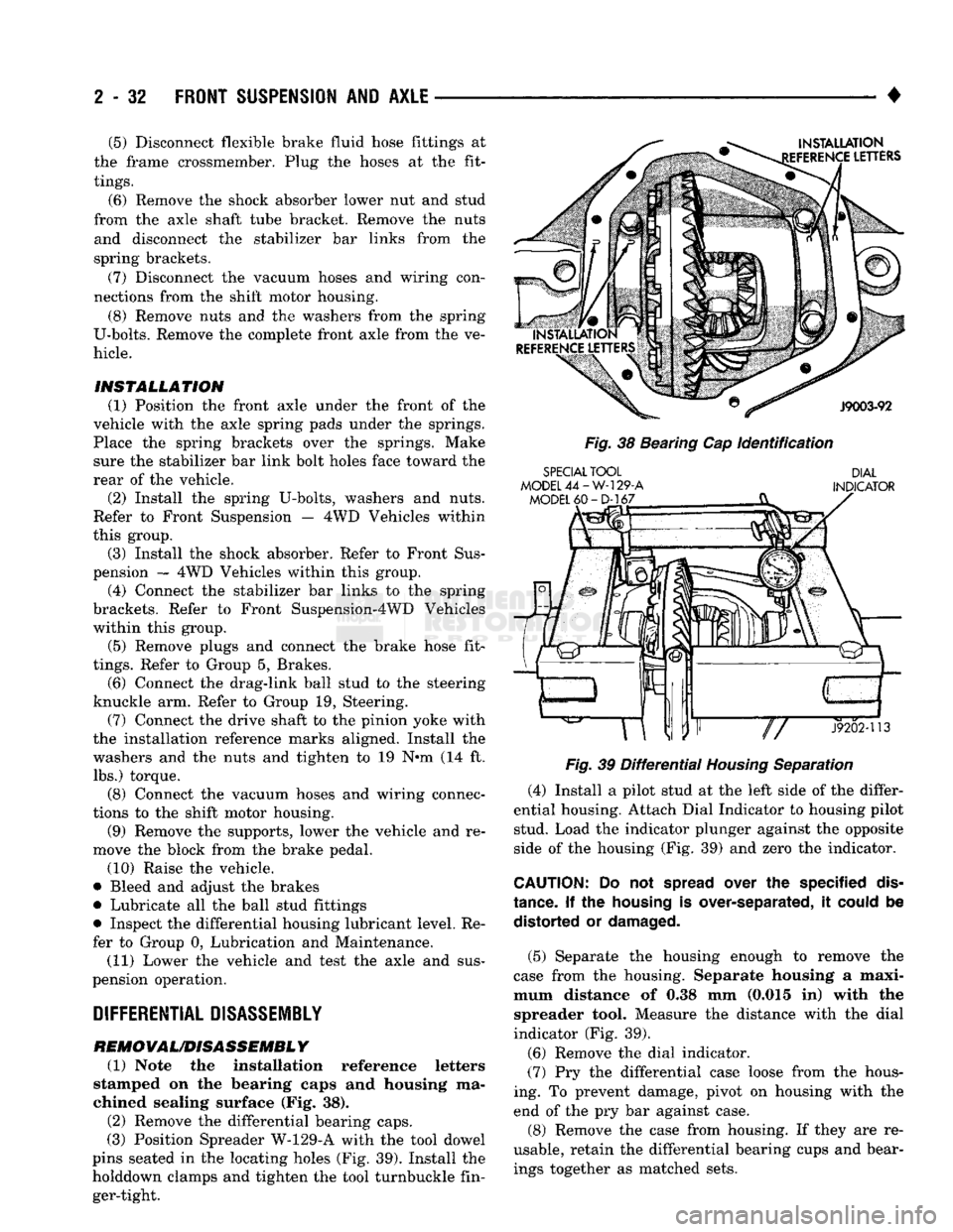
REMOVAL/DISASSEMBLY (1) Note the installation reference letters
stamped on the bearing caps and housing ma
chined sealing surface (Fig. 38). (2) Remove the differential bearing caps.
(3) Position Spreader W-129-A with the tool dowel
pins seated in the locating holes (Fig. 39). Install the
holddown clamps and tighten the tool turnbuckle fin ger-tight.
INSTALLATION
EFERENCE
LETTERS
J9003-92
Fig.
38 Bearing Cap
Identification
SPECIAL
TOOL
MODEL
44-W-129-A
MODEL
60-D-167
DIAL
INDICATOR
«ar"P—
J9202-113
Fig.
39
Differential
Housing
Separation
(4) Install a pilot stud at the left side of the differ
ential housing. Attach Dial Indicator to housing pilot stud. Load the indicator plunger against the opposite
side of the housing (Fig. 39) and zero the indicator.
CAUTION:
Do not
spread
over the specified
dis
tance.
If the
housing
is over-separated, it
could
be distorted or
damaged.
(5) Separate the housing enough to remove the
case from the housing. Separate housing a maxi
mum distance of 0.38 mm (0.015 in) with the spreader tool. Measure the distance with the dial
indicator (Fig. 39).
(6) Remove the dial indicator.
(7) Pry the differential case loose from the hous
ing. To prevent damage, pivot on housing with the end of the pry bar against case.
(8) Remove the case from housing. If they are re
usable, retain the differential bearing cups and bear ings together as matched sets.
Page 200 of 1502
•
BRAKES
5 - 13
COMBINATION VALVE OPERATION
METERING (HOLD-OFF) VALVE The metering valve is used to balance brake action
between the front disc and rear drum brakes. The
valve meters (holds-off) full apply pressure to the front disc brakes until the rear brakeshoes are in full
contact with the drums.
The valve is designed to maintain front brake fluid
pressure at 3-30 psi until the hold-off limit of 117 psi is reached. At this point, the metering valve opens completely permitting full fluid apply pressure to the
front disc brakes.
PRESSURE DIFFERENTIAL SWITCH AND VALVE The pressure differential switch is connected to the
brake warning light. The switch is triggered by movement of the switch valve. The purpose of the switch is to monitor fluid pressure in the separate
front/rear brake hydraulic circuits.
A decrease or loss of fluid pressure in either hy
draulic circuit will cause the switch valve to shuttle
forward or rearward in response to a pressure differ ential.
Movement of the switch valve will push the switch
plunger upward. This closes the switch internal con tacts completing the electrical circuit to the warning light. The switch valve will remain in an actuated
position until repair restores system pressures to nor mal levels.
COMBINATION VALVE TESTING
TESTING METERING VALVE Metering valve operation can be checked visually
and with the aid of a helper.
Observe the metering valve stem while a helper
applies and releases the brakes. If the valve is oper
ating correctly, the stem will extend slightly when
the brakes are applied and retract when the brakes are released.
If the valve is faulty, replace the entire combina
tion valve as an assembly.
TESTING PRESSURE DIFFERENTIAL SWITCH (1) Have helper sit in drivers seat to observe brake
warning light and to operate brake pedal.
(2) Raise vehicle on hoist.
(3) Connect bleed hose to left or right rear wheel
cylinder. Then immerse hose end in glass jar par
tially filled with brake fluid.
(4) Have helper press and hold brake pedal all the
way down and observe warning light.
(a) If warning light illuminates, switch is operat
ing correctly. (b) If light fails to illuminate, check circuit fuse,
bulb and wiring. Repair as necessary and repeat test steps (3) and (4). (5) If warning light still fails to illuminate, check
brakelight and park brake switches (and wiring) with test lamp. Repair or replace parts as necessary and test differential pressure switch operation again.
(6) If warning light still does not illuminate,
switch is faulty. Replace combination valve, bleed
brakes and verify proper switch and valve operation.
COMBINATION VALVE REMOVAL/INSTALLATION
VALVE REMOVAL (1) Raise vehicle on hoist.
(2) Mark or tag brake lines connected to valve for
assembly reference.
(3) Disconnect lines at valve (Fig. 8).
(4) Disconnect wires from differential pressure
switch.
(5) Remove bolts attaching valve to frame bracket
and remove valve.
VALVE INSTALLATION (1) Mount new valve on bracket and tighten valve
and bracket screws/nuts securely.
(2) Connect brakelines to valve. Tighten fittings to
16 N*m (145 in. lbs.)
(3) Connect wires to pressure differential switch
terminal. (4) Bleed brakes.
(5) Lower vehicle and verify proper brake opera
tion.
BRAKE
LINES AND
HOSES
BRAKE LINE AND HOSE INSPECTION Flexible rubber hose is used at both front brakes
and at the rear axle junction block. Inspect the hoses
whenever the brake system is serviced, at every en gine oil change, or whenever the vehicle is in for ser
vice.
Inspect the hoses for surface cracking, scuffing, or
worn spots. Replace any brake hose immediately if
the fabric casing of the hose is exposed by cracks or abrasion.
Also check brake hose installation. Faulty installa
tion can result in kinked, twisted hoses, or contact with the wheels and tires or other chassis compo
nents.
All of these conditions can lead to scuffing,
cracking and eventual failure.
The steel brake lines should be inspected periodi
cally for evidence of corrosion, twists, kinks, leaks, or
other damage. Heavily corroded lines will eventually
rust through causing leaks. In any case, corroded or damaged brake lines should be replaced.
Page 204 of 1502
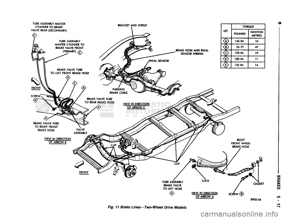
TUBE ASSEMBLY MASTER
CYLINDER TO BRAKE
VALVE REAR (SECONDARY)
BRACKET
AND SHIELD
BRAKE
HOSE AND RWAL
SENSOR
WIRING LET.
TORQUE
LET. POUNDS NEWTON
METRES
x!^ 145 IN.
16
XX 35 FT.
47
170 IN. 19
100 IN.
11
125
IN.
14
BRAKE
VALVE TUBE
TO RIGHT FRONT
BRAKE
HOSE
VIEW IN DIRECTION OF ARROW A
SCREW
<§>
GASKET
8905-54
Fig. 11
Brake
Lines—Two-Wheel
Drive
Models
Page 210 of 1502
•
BRAKES
5 - 23
VACUUM PUMP OPERATION
Vacuum pump output is transmitted to the power
brake booster through a supply hose. The hose is con nected to an outlet port on the pump housing and to
the check valve in the power brake booster.
Pump output ranges from a minimum of 8.5 to 25
inches vacuum. The pump rotor and vanes are rotated by the pump
drive gear. The drive gear is operated by the cam
shaft gear. Booster vacuum level is monitored by a warning
switch (Fig. 2). The switch consists of a vacuum
chamber that measures vacuum level and a sensor in
circuit with the brake warning light. The vacuum chamber is connected to the booster
check valve by a vacuum supply hose. A wire har
ness connects the switch sensor to the brake warning
light. If booster vacuum falls below 8.5 inches for 8-10 seconds or more, the switch sensor completes
the circuit to the warning light causing it to illumi
nate.
VACUUM PUMP DIAGNOSIS
Vacuum pump diagnosis involves checking pump
output with a vacuum gauge. The low vacuum warn
ing switch can also be checked with a vacuum gauge.
Refer to the diagnosis procedure in this section. A standard vacuum gauge can be used to check
pump output when necessary. Simply disconnect the
pump supply hose and connect a vacuum gauge to
the outlet port for testing purposes. Vacuum should
hold steady in a range of approximately 8.5 to 25 inches at various engine speeds.
DIAGNOSING LOW VACUUM OUTPUT CONDITION A low booster vacuum condition or a faulty low
vacuum warning switch will cause the brake warn ing light to illuminate. If the light does go on and in
dicates the existence of a low vacuum condition,
check the vacuum pump, booster and warning switch
as follows:
(1) Check vacuum pump oil feed line. Verify that
line connections are secure and not leaking. If leak age is noted and pump is noisy, replace pump.
(2) Disconnect supply hose to booster. Connect vac
uum gauge to this hose and run engine at various
throttle openings. Output should range from 8.5 to 25 inches vacuum. If vacuum is consistently below
8.5 inches, problem is with vacuum hoses or pump
component. If output is within specified limits, con
tinue testing.
(3) Check booster operation as described in diagno
sis section. Replace check valve, vacuum hoses, or
booster if necessary. However, if booster operation is correct but warning light is still on, continue testing. (4) Disconnect vacuum hose at warning switch.
Plug hose and connect hand vacuum pump to switch. (5) Start and run engine.
(6) Apply 8.5 to 9 inches of vacuum to warning
switch and observe warning light. If light goes out,
switch vacuum hose is either loose or leaking. If
light remains on, leave engine running and continue
testing.
(7) Apply 20-25 inches vacuum to switch and ob
serve warning light operation. If light now goes out,
switch is at fault and should be replaced. If light re
mains on, continue testing.
(8) Reconnect vacuum hoses and replace original
warning switch with known good switch. Run engine and observe warning light operation. If light is now
off, old switch is faulty. If light remains on, problem
is in wiring between switch and warning light.
VACUUM-STEERING PUMP
ASSEMBLY
REMOVAL
(1) Disconnect battery negative cable.
(2) Position drain pan under power steering pump.
(3) Disconnect vacuum and steering pump hoses
from respective pumps (Fig. 3).
Fig.
3
Vacuum
And Steering
Pump Hose
Connections
(4) Disconnect oil pressure sender wires at sender
(Fig. 4).
(5) Remove oil pressure sender (Fig. 4).
(6) Disconnect lubricating oil feed line from fitting
at underside of vacuum pump (Fig. 5).
(7) Remove lower bolt that attaches pump assem
bly to engine block (Fig. 6).
(8) Remove bottom, inboard nut that attaches
adapter to steering pump (Fig. 6). This nut secures a
small bracket to engine block. Nut and bracket must
be removed before pump assembly can be removed from block.