1993 DODGE TRUCK mirror
[x] Cancel search: mirrorPage 322 of 1502
•
ELECTRICAL
ELECTRICAL
8A - 1
Group
AUDIO
SYSTEMS
8F
BATTERY/STARTER/GENERATOR
SERVICE
.. 8B
BATTERY/STARTING/CHARGING
SYSTEMS
DIAGNOSTICS
8A
HORNS
8G
IGNITION
SYSTEMS
8D
INSTRUMENT PANEL AND
GAUGES
8E
LAMPS
8L
POWER
LOCKS
8P
INDEX
Group
POWER
MIRRORS
8T
POWER
WINDOWS 8S
REAR
WINDOW DEFOGGER 8N
TURN
SIGNALS
AND HAZARD WARNING
FLASHERS
8J
VEHICLE
SPEED
CONTROL SYSTEM 8H WARNING BUZZER SYSTEM 8U
WINDSHIELD WIPERS AND
WASHERS
8K
WIRING DIAGRAMS 8W
BATTERY/STARTING/CHARGING SYSTEMS DIAGNOSTICS
CONTENTS
page
page
BATTERY TEST
PROCEDURES
2 GENERATOR TEST
PROCEDURES
ON VEHICLE . 13
ENGINE
STARTER MOTOR TEST
PROCEDURES
..9 SPECIFICATIONS 18
GENERAL
INFORMATION 1
GENERAL INFORMATION
The Battery, Starting, and Charging Systems oper
ate with one another, and therefore, must be thor
oughly tested as a complete system. In order for the
vehicle to start and charge properly, it must have a
battery that will perform to specifications. The starter
motor, generator, wiring, and electronics also must
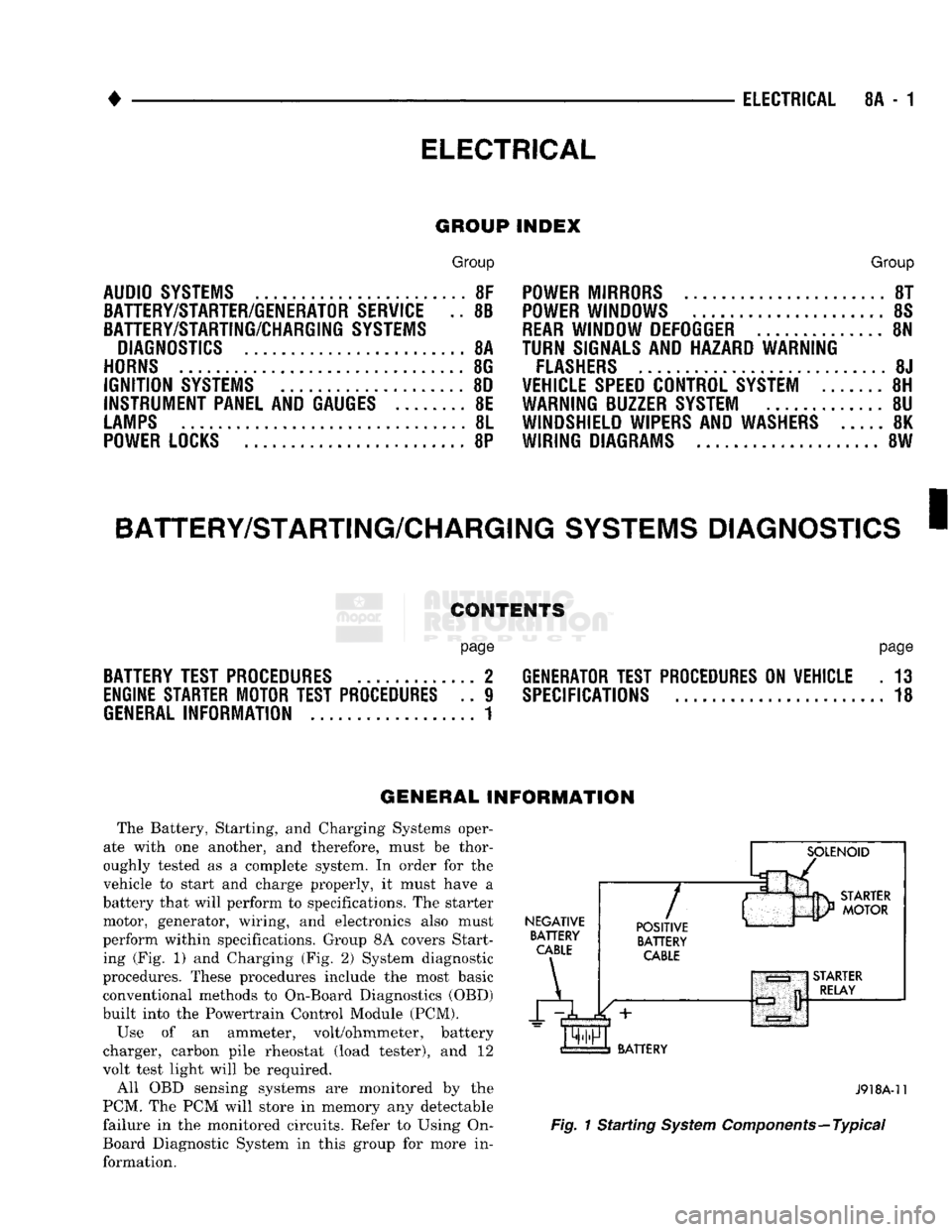
perform within specifications. Group 8A covers Start ing (Fig. 1) and Charging (Fig. 2) System diagnostic
procedures. These procedures include the most basic
conventional methods to On-Board Diagnostics (OBD)
built into the Powertrain Control Module (PCM).
Use of an ammeter, volt/ohmmeter, battery
charger, carbon pile rheostat (load tester), and 12
volt test light will be required.
All OBD sensing systems are monitored by the
PCM. The PCM will store in memory any detectable
failure in the monitored circuits. Refer to Using On-
Board Diagnostic System in this group for more in formation.
NEGATIVE
BATTERY
CABLE
A
7
POSITIVE
BATTERY
CABLE
BATTERY
J918A-11
Fig.
1 Starting
System
Components—Typical
Page 398 of 1502
INSTRUMENT
PANEL
AND
GAUGES
8E - 17
HEATER
A/C
CONTROL
REMOVAL
(1) Remove map lamp.
(2) Remove cluster bezel (refer to Cluster Bezel Re
moval).
(3) Remove 2 control attaching screws.
(4) Pull control rearward.
(5) Disconnect blower switch wiring.
(6) Disconnect wires to pushbutton switch (three
connectors). (7) Disconnect illumination lamp.
(8) Disconnect vacuum harness.
(9) Disconnect temperature cable.
(10) Remove control.
INSTALLATION
(1) Position control near panel.
(2) Connect temperature cable (see Group 24 -
Heating and Air Conditioning).
(3) Connect vacuum harness. (4) Connect illumination lamp.
(5) Attach 3 wire connectors to pushbutton switch.
(6) Connect wires to blower motor switch.
(7) Push control into panel.
(8) Install 2 control mounting screws.
(9) Install cluster bezel.
(10) Install map lamp.
INSTRUMENT
PANEL SWITCHES
HEADLAMP
SWITCH
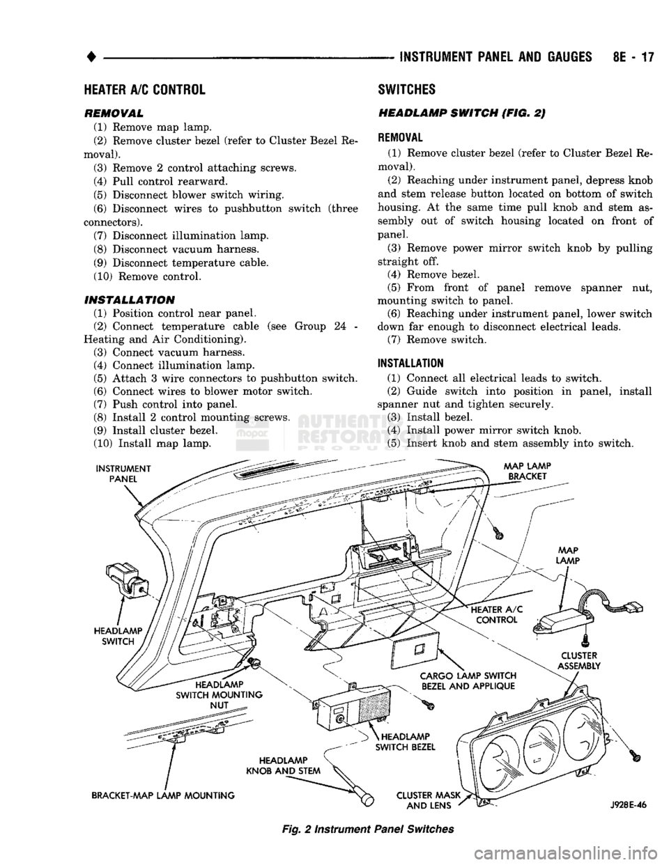
(FIG. 2)
REMOVAL
(1) Remove cluster bezel (refer to Cluster Bezel Re
moval).
(2) Reaching under instrument panel, depress knob
and stem release button located on bottom of switch
housing. At the same time pull knob and stem as sembly out of switch housing located on front of
panel.
(3) Remove power mirror switch knob by pulling
straight off.
(4) Remove bezel.
(5) From front of panel remove spanner nut,
mounting switch to panel. (6) Reaching under instrument panel, lower switch
down far enough to disconnect electrical leads. (7) Remove switch.
INSTALLATION
(1) Connect all electrical leads to switch.
(2) Guide switch into position in panel, install
spanner nut and tighten securely.
(3) Install bezel.
(4) Install power mirror switch knob.
(5) Insert knob and stem assembly into switch.
AAAP LAMP
BRACKET
HEADLAMP SWITCH
CLUSTER
ASSEMBLY
HEADLAMP
SWITCH MOUNTING NUT
CARGO
LAMP SWITCH
BEZEL
AND APPLIQUE
HEADLAMP
KNOB AND STEM
BRACKET-MAP LAMP MOUNTING HEADLAMP
SWITCH BEZEL
CLUSTER AAASK AND LENS
J928E-46
Fig.
2 Instrument
Panel
Switches
Page 399 of 1502
8E
- 18
INSTRUMENT PANEL
AND
GAUGES
—
•
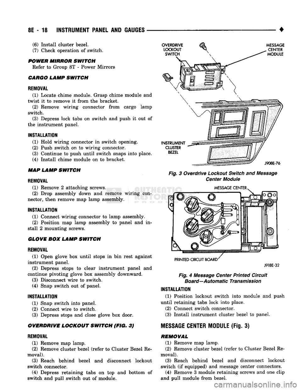
Fig.
3 Overdrive
Lockout
Switch
and
Message
Center
Module
J918E-32
Fig.
4
Message
Center Printed Circuit
Board—Automatic
Transmission
INSTALLATION
(1) Position lockout switch into module and push
until retaining tabs lock into place.
(2) Connect switch connector.
(3)
Install instrument cluster bezel to panel.
MESSAGE
CENTER MODULE
(Fig. 3) REMOVAL (1) Remove map lamp.
(2) Remove cluster bezel (refer to Cluster Bezel Re
moval).
(3)
Reach behind bezel and disconnect lockout
switch (if equipped) and message center connectors.
(4)
Remove 3 module retaining screws and one clip
and pull module from bezel.
(6)
Install cluster bezel.
(7)
Check operation of switch.
POWER MIRROR SWITCH Refer to Group 8T - Power Mirrors
CARGO LAMP SWITCH
REMOVAL
(1) Locate chime module. Grasp chime module and
twist it to remove it from the bracket. (2) Remove wiring connector from cargo lamp
switch.
(3)
Depress lock tabs on switch and push it out of
the instrument panel.
INSTALLATION
(1) Hold wiring connector in switch opening.
(2) Push switch on to wiring connector.
(3)
Continue to push until switch snaps into place.
(4)
Install chime module on to bracket.
MAP LAMP SWITCH
REMOVAL
(1) Remove 2 attaching screws.
(2) Drop assembly down and remove wiring con
nector, then remove map lamp assembly.
INSTALLATION
(1) Connect wiring connector to lamp assembly. (2) Position map lamp assembly to panel and in
stall 2 mounting screws.
GLOVE BOX LAMP SWITCH
REMOVAL
(1) Open glove box until stops in bin rest against
instrument panel.
(2) Depress stops to clear instrument panel and
continue pivoting glove box assembly downward.
(3)
Disconnect wire to switch.
(4)
Snap switch out of panel.
INSTALLATION
(1) Snap switch into panel.
(2) Connect wire to switch.
(3)
Depress stops and close glove box door.
OVERDRIVE LOCKOUT SWITCH (FIG. 3)
REMOVAL
(1) Remove map lamp.
(2) Remove cluster bezel (refer to Cluster Bezel Re
moval).
(3)
Reach behind bezel and disconnect lockout
switch connector.
(4)
Depress retaining tabs on top and bottom of
switch and pull switch out of module.
Page 468 of 1502
POWER
MIRRORS
CONTENTS
page
SERVICE PROCEDURES
2
GENERAL
INFORMATION
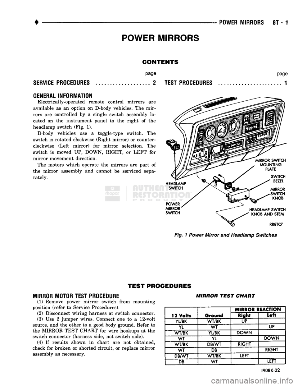
Electrically-operated remote control mirrors are
available as an option on D-body vehicles. The mir
rors are controlled by a single switch assembly lo
cated on the instrument panel to the right of the
headlamp switch (Fig. 1). D-body vehicles use a toggle-type switch. The
switch is rotated clockwise (Right mirror) or counter
clockwise (Left mirror) for mirror selection. The
switch is moved UP, DOWN, RIGHT, or LEFT for
mirror movement direction. The motors which operate the mirrors are part of
the mirror assembly and cannot be serviced sepa
rately.
page
TEST PROCEDURES
...................... 1 Fig. 1 Power Mirror and Headlamp Switches
TEST
PROCEDURES
MIRROR MOTOR TEST PROCEDURE
(1) Remove power mirror switch from mounting
position (refer to Service Procedures). (2) Disconnect wiring harness at switch connector.
(3) Use 2 jumper wires. Connect one to a
12-volt
source, and the other to a good body ground. Refer to
the MIRROR TEST CHART for wire hookups at the switch connector (harness side, not switch side), (4) If results shown in chart are not obtained,
check for broken or shorted circuit, or replace mirror assembly as necessary. MIRROR
TEST
CHART
12 Volts Ground MIRROR REACTION
12 Volts Ground Right
Left
Yl/BK
1
WT/BK UP
YL WT UP
WT/BK
YL/BK
DOWN
WT YL DOWN
WT/BK DB/WT RIGHT
WT
DB
RIGHT
DB/WT WT/BK LEFT
DB
WT LEFT
J908K-22
Page 469 of 1502
8T - 2
POWER MIRRORS
•
MIRROR
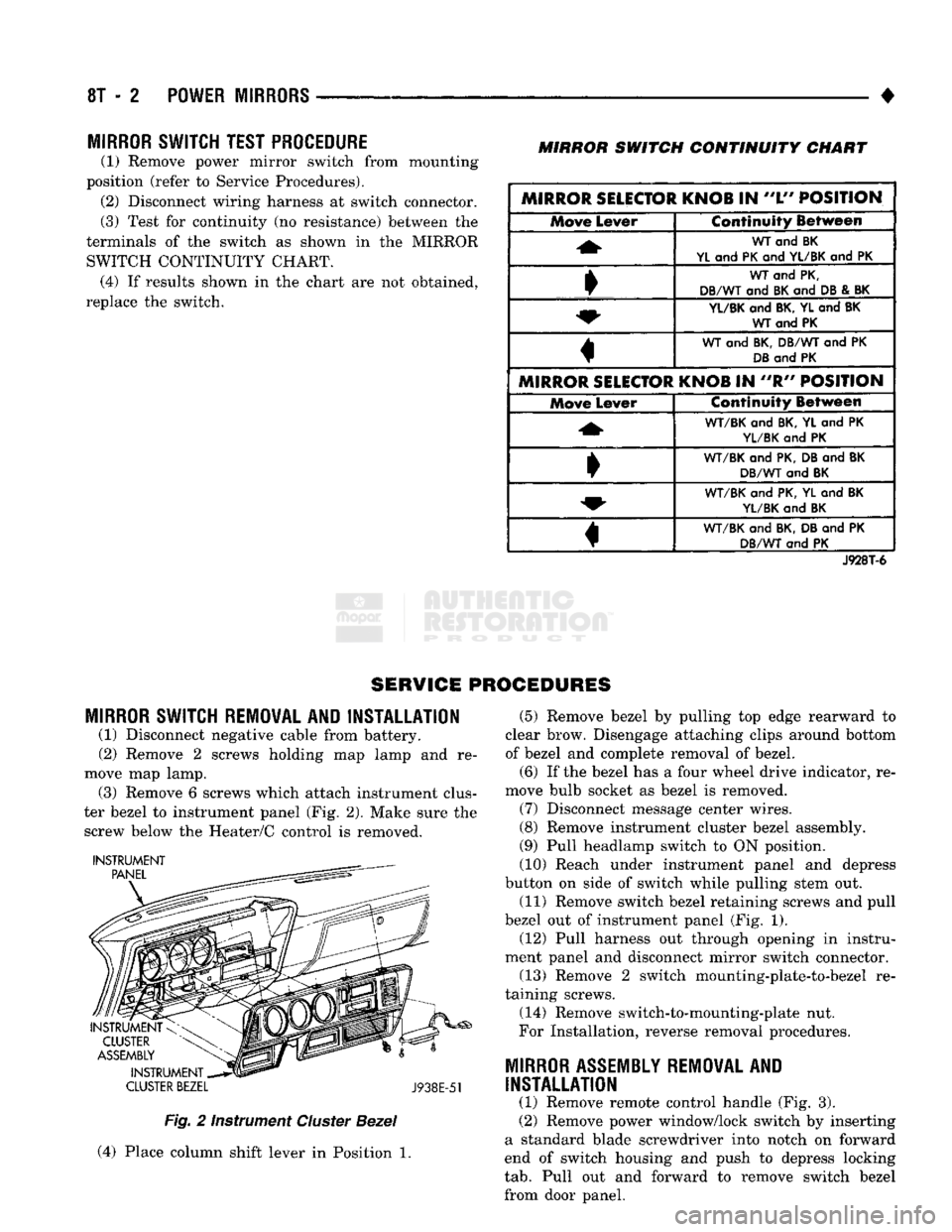
SWITCH TEST PROCEDURE
(1) Remove power mirror switch from mounting
position (refer to Service Procedures). (2) Disconnect wiring harness at switch connector.
(3) Test for continuity (no resistance) between the
terminals of the switch as shown in the MIRROR SWITCH CONTINUITY CHART. (4) If results shown in the chart are not obtained,
replace the switch.
MIRROR
SWITCH
CONTINUITY
CHART
MIRROR SELECTOR KNOB
IN
"L"
POSITION Move
Lever Continuity Between
WT
and BK
YL
and
PK
and
YL/BK
and PK
WT
and
PK,
DB/WT
and
BK
and
DB
&
BK
YL/BK
and
BK, YL
and
BK WT and PK
WT
and
BK, DB/WT
and PK
DB
and
PK
MIRROR SELECTOR KNOB
IN "R"
POSITION Move
Lever Continuity Between
WT/BK
and
BK,
YL and PK
YL/BK
and PK
•
WT/BK
and
PK, DB
and
BK
DB/WT
and
BK
WT/BK
and
PK, YL
and
BK
YL/BK
and
BK
«
WT/BK
and
BK, DB
and PK
DB/WT
and PK
J928T-6
SERVICE PROCEDURES
MIRROR
SWITCH REMOVAL AND INSTALLATION
(1) Disconnect negative cable from battery.
(2) Remove 2 screws holding map lamp and re
move map lamp. (3) Remove 6 screws which attach instrument clus
ter bezel to instrument panel (Fig. 2). Make sure the screw below the Heater/C control is removed.
INSTRUMENT
CLUSTER
BEZEL
J938E-51
Fig.
2 Instrument
Cluster
Bezel
(4) Place column shift lever in Position 1. (5) Remove bezel by pulling top edge rearward to
clear brow. Disengage attaching clips around bottom
of bezel and complete removal of bezel.
(6) If the bezel has a four wheel drive indicator, re
move bulb socket as bezel is removed. (7) Disconnect message center wires.
(8) Remove instrument cluster bezel assembly.
(9) Pull headlamp switch to ON position.
(10) Reach under instrument panel and depress
button on side of switch while pulling stem out.
(11) Remove switch bezel retaining screws and pull
bezel out of instrument panel (Fig. 1). (12) Pull harness out through opening in instru
ment panel and disconnect mirror switch connector.
(13) Remove 2 switch mounting-plate-to-bezel re
taining screws.
(14) Remove switch-to-mounting-plate nut.
For Installation, reverse removal procedures.
MIRROR
ASSEMBLY
REMOVAL
AND
INSTALLATION
(1) Remove remote control handle (Fig. 3).
(2) Remove power window/lock switch by inserting
a standard blade screwdriver into notch on forward
end of switch housing and push to depress locking
tab.
Pull out and forward to remove switch bezel
from door panel.
Page 470 of 1502
•
POWER
MIRRORS
8T - 3
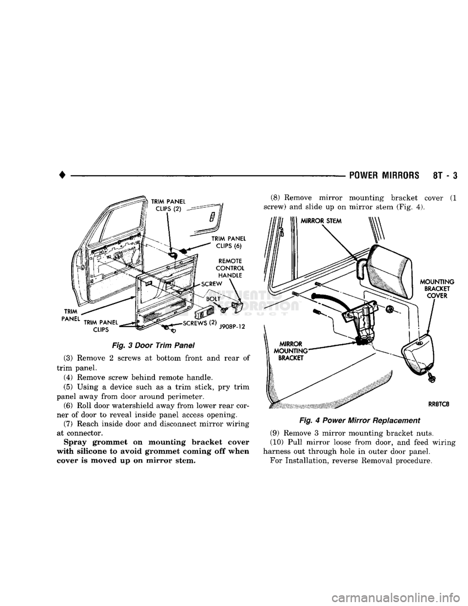
Fig.
3
Door
Trim
Panel
(3) Remove 2 screws at bottom front and rear of
trim panel. (4) Remove screw behind remote handle.
(5) Using a device such as a trim stick, pry trim
panel away from door around perimeter.
(6) Roll door watershield away from lower rear cor
ner of door to reveal inside panel access opening. (7) Reach inside door and disconnect mirror wiring
at connector. Spray grommet on mounting bracket cover
with silicone to avoid grommet coming off when
cover is moved up on mirror stem. (8) Remove mirror mounting bracket cover (1
screw) and slide up on mirror stem (Fig. 4).
Fig.
4
Power
Mirror Replacement
(9) Remove 3 mirror mounting bracket nuts.
(10) Pull mirror loose from door, and feed wiring
harness out through hole in outer door panel.
For Installation, reverse Removal procedure.
Page 477 of 1502
8W
- 2
WIRING
DIAGRAMS
•
WIRE CODE
IDENTIFICATION
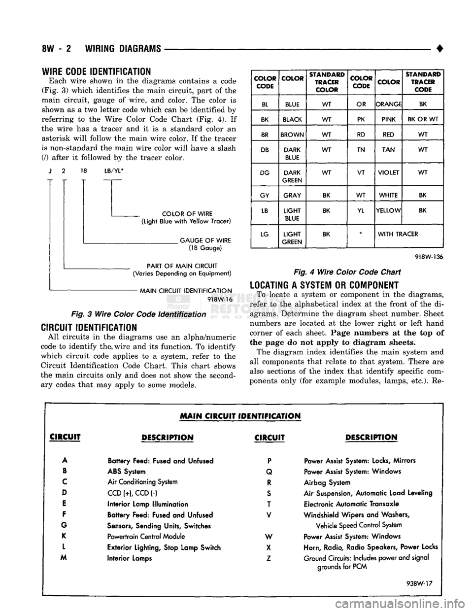
Each wire shown in the diagrams contains a code
(Fig. 3) which identifies the main circuit, part of the
main circuit, gauge of wire, and color. The color is shown as a two letter code which can be identified by
referring to the Wire Color Code Chart (Fig. 4). If
the wire has a tracer and it is a standard color an asterisk will follow the main wire color. If the tracer
is non-standard the main wire color will have a slash (/) after it followed by the tracer color. 18
LB/YL*
COLOR
OF
WIRE
(Light
Blue
with
Yellow
Tracer)
.
GAUGE
OF
WIRE
(18
Gauge)
PART
OF
AAAIN CIRCUIT
(Varies
Depending
on
Equipment)
AAAIN CIRCUIT
IDENTIFICATION
918W-16
Fig.
3
Wire
Color
Code
Identification
CIRCUIT IDENTIFICATION
All circuits in the diagrams use an alpha/numeric
code to identify the, wire and its function. To identify
which circuit code applies to a system, refer to the
Circuit Identification Code Chart. This chart shows
the main circuits only and does not show the second ary codes that may apply to some models.
COLOR
CODE COLOR
STANDARD
TRACER
COLOR COLOR
CODE
COLOR
STANDARD
TRACER
CODE
BL BLUE WT
OR ORANGE
BK
BK
BLACK
WT PK
PINK
BK
OR WT
BR
BROWN
WT RD
RED WT
DB DARK
BLUE WT
TN
TAN WT
DG DARK
GREEN WT
VT
VIOLET
WT
GY GRAY
BK
WT
WHITE
BK
LB
LIGHT
BLUE
BK
YL YELLOW
BK
LG
LIGHT
GREEN
BK
*
WITH
TRACER
918W-136
Fig.
4
Wire
Color
Code
Chart
LOCATING
A
SYSTEM
OR
COMPONENT
To locate a system or component in the diagrams,
refer to the alphabetical index at the front of the di agrams. Determine the diagram sheet number. Sheet
numbers are located at the lower right or left hand
corner of each sheet. Page numbers at the top of
the page do not apply to diagram sheets. The diagram index identifies the main system and
all components that relate to that system. There are
also sections of the index that identify specific com
ponents only (for example modules, lamps, etc.). Re-
MAIN
CIRCUIT IDENTIFICATION
CIRCUIT
DESCRIPTION
CIRCUIT
DESCRIPTION
A
Battery
Feed: Fused and Unfused
P
Power
Assist
System:
Locks,
Mirrors
B
ABS
System Q Power
Assist
System: Windows
C
Air Conditioning System
R
Airbag System
D
CCD
(+),
CCD
(-)
S
Air Suspension, Automatic Load Leveling
E
Interior
Lamp
Illumination
T Electronic Automatic Transaxle
F
Battery
Feed: Fused and Unfused
V
Windshield Wipers and Washers,
G
Sensors,
Sending Units, Switches Vehicle Speed Control System
K
Powertrain
Central
Module W Power
Assist
System: Windows
L
Exterior
Lighting, Stop Lamp Switch
X
Horn, Radio, Radio Speakers, Power Locks
M
Interior
Lamps
Z
Ground Circuits: Includes power and signal
Interior
Lamps
grounds
for PCM
938W-17
Page 482 of 1502
CAVITY
FUSE/
COLOR ITEMS FUSED
CAVITY
FUSE/
COLOR ITEMS FUSED
10
11
12
13 2 AMP
GY VEHICLE SPEED CONTROL
5 AMP TN
GAUGES,
BRAKE WARNING LAMP, SEAT BELT WARNING
LAMP, BUZZER, LOW OIL LAMP, CHECK ENGINE LAMP,
ANTI-LOCK LAMP, TAILGATE OPEN LAMP, 4WD LAMP, O/D MODULE, LOW FUEL LAMP,
WAIT
TO START LAMP
WATER-IN-FUEL LAMP 14
3 AMP
VT
20 AMP YL BACK-UP LAMP, HEATED REAR WINDOW
15 10 AMP
RD
ILLUMINATION
LAMPS, A/C HEATER LAMP, ASH
RECEIVER LAMP, RADIO LAMP, TRANSMISSION
OVERDRIVE SWITCH LAMP, TACHOMETER LAMP, HEATED REAR WINDOW SWITCH LAMP.
RADIO AND CLOCK MEMORY, POWER MIRRORS, GLOVE BOX LAMP, DOME LAMP, READING LAMP, MAP LAMP,
CARGO LAMP,
IGNITION
SWITCH LAMP, UNDERHOOD LAMP
20 AMP YL FUSE CAVITY #14,
TAIL
LAMPS, PARKING LAMPS, SIDE
AAARKER
LAMPS, LICENSE LAMPS, FRONT AND REAR CLEARANCE LAMPS, RADIO INTENSITY, HORNS
20 AMP YL STOP LAMPS, KEY-IN & HEADLAMP ON BUZZER, RWAL
MODULE 30 AMP
CIRCUIT
BREAKER
TURN
SIGNAL
FLASHER 20 AMP
YL POWER DOOR LOCKS
15 AMP
BL
CIGAR LIGHTER
10 AMP RD RADIO AND CLOCK
20 AMP YL
TURN
SIGNALS, TACHOMETER PROVISION,
RWAL MODULE
20 AMP YL WINDSHIELD WIPERS
30 AMP LG A/C - HEATER BLOWER MOTOR
30 AMP
C/BRKR
POWER WINDOWS
20 AMP YL HAZARD FLASHER
AMPS
FUSE
COLOR
2 GY GRAY
3 VT
VIOLET
5 TN
TAN
10 RD
RED
15
BL
BLUE
20 YL YELLOW
30 LG
LIGHT
GREEN HAZARD
FLASHER
J938W-94
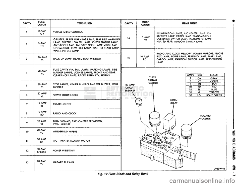
Fig. 12 Fuse Block and
Relay
Bank