1993 DODGE TRUCK height adjustment
[x] Cancel search: height adjustmentPage 59 of 1502
2
- 6
FRONT
SUSPENSION
AND
AXLE
•
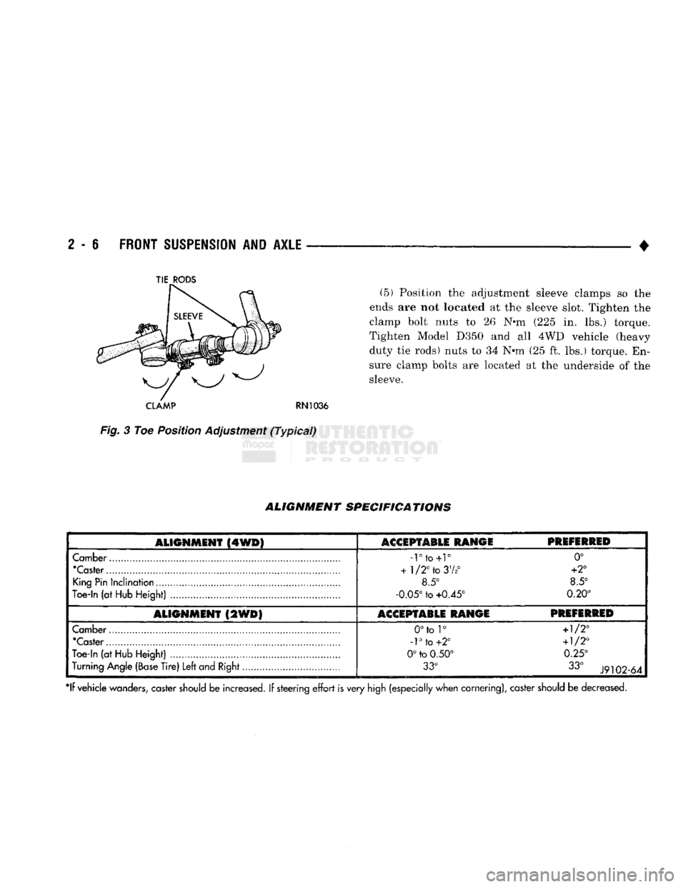
(5) Position the adjustment sleeve clamps so the
ends are not located at the sleeve slot. Tighten the
clamp bolt nuts to 26 N*m (225 in. lbs.) torque.
Tighten Model D350 and all 4WD vehicle (heavy
duty tie rods) nuts to 34 N*m (25 ft. lbs.) torque. En
sure clamp bolts are located at the underside of the
sleeve.
CLAMP
RN1036
Fig.
3 Toe Position Adjustment
(Typical)
ALIGNMENT
SPECIFICATIONS
ALIGNMENT
(4WD)
ASGSPTABLE RANGE
PREFERRED
Camber
-rto+r
0°
"Caster
+
1/2°
to
37*°
+2°
King
Pin
Inclination
8.5° 8.5°
Toe-In
(at
Hub
Height)
-0.05°
to
+0.45° 0.20°
ALIGNMENT
(2WD)
ACCEPTABLE RANGE PREFERRED
Camber
0°to 1°
+1/2°
'Caster
-1°
to
+2°
+1/2°
Toe-in
(at
Hub
Height)
0°
to
0.50° 0.25°
Turning
Angle
(Base
Tire)
Left
and
Right
33°
33°
J9102-64
*lf vehicle
wanders,
caster
should
be increased. If steering
effort
is very
high
(especially when cornering), caster
should
be decreased.
TIE
RODS
Page 91 of 1502
2
- 38
FRONT
SUSPENSION
AND
AXLE
•
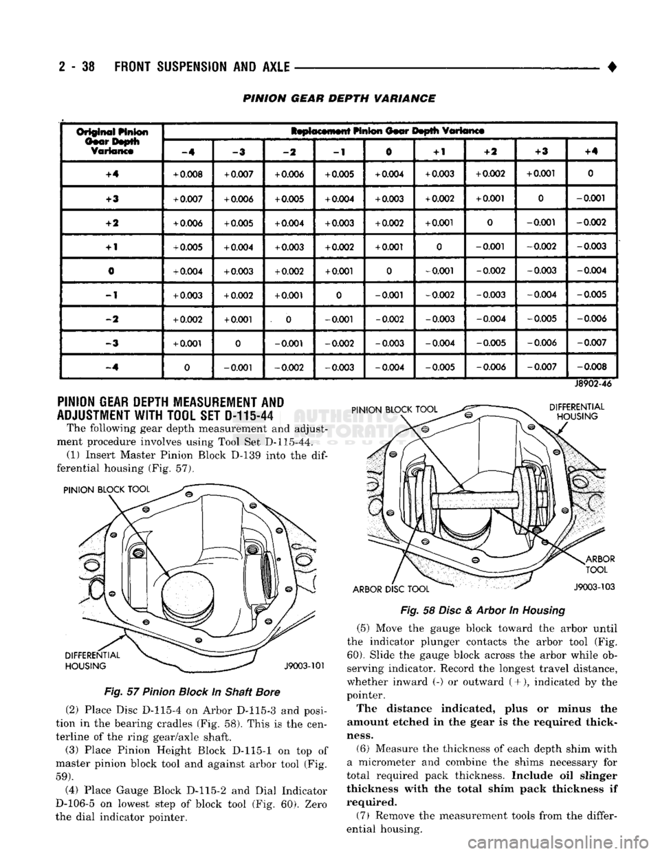
PINION GEAR DEPTH VARIANCE
Or§@ift^i
Linton
IsptocMnwtt
HnS®n
Oior Itoplli
fflttanct
Or§@ift^i
Linton
-4
-2
-1
0
+
1
-ft
+3
+4
+4
+
0.008
+
0.007
+
0.006
+
0.005
+
0.004
+
0.003
+
0.002
+
0.001
0
+3
+
0.007
+
0.006
+
0.005
+
0.004
+
0.003
+
0.002
+
0.001
0
-0.001
+2
+
0.006
+
0.005
+
0.004
+
0.003
+
0.002
+
0.001
0
-0.001
-0.002
+
1
+
0.005
+
0.004
+
0.003
+
0.002
+
0.001
0
-0.001
-0.002
-0.003
0
+
0.004
+
0.003
+
0.002
+
0.001
0
-0.001
-0.002
-0.003
-0.004
-1
+
0.003
+
0.002
+
0.001
0
-0.001
-0.002
-0.003 -0.004
-0.005
-2
+
0.002
+
0.001
. 0
-0.001
-0.002
-0.003 -0.004
-0.005 -0.006
-3
+
0.001
0
-0.001
-0.002
-0.003 -0.004
-0.005 -0.006
-0.007
-.4
0
-0.001
-0.002
-0.003 -0.004 -0.005
-0.006
-0.007
-0.008
PINION
GEAR
DEPTH
MEASUREMENT
AND
ADJUSTMENT
WITH TOOL SET D-11144
The following gear depth measurement and adjust
ment procedure involves using Tool Set D-115-44. (1) Insert Master Pinion Block D-139 into the
dif
ferential housing (Fig. 57).
PINION BLOCK TOOL PINION BLOCK TOOL
J8902-46
DIFFERENTIAL
HOUSING
ARBOR
DISC
TOOL
ARBOR
TOOL
J9003-103
DIFFERENTIAL
HOUSING
J9003-101
Fig.
57
Pinion
Block
In Shaft
Bore
(2) Place Disc D-115-4 on Arbor D-115-3 and posi
tion in the bearing cradles (Fig. 58). This is the cen
terline of the ring gear/axle shaft. (3) Place Pinion Height Block D-115-1 on top of
master pinion block tool and against arbor tool (Fig.
59).
(4) Place Gauge Block D-115-2 and Dial Indicator
D-106-5 on lowest step of block tool (Fig. 60). Zero
the dial indicator pointer.
Fig.
58
Disc
&
Arbor
In
Housing
(5) Move the gauge block toward the arbor until
the indicator plunger contacts the arbor tool (Fig.
60).
Slide the gauge block across the arbor while ob
serving indicator. Record the longest travel distance,
whether inward (-) or outward (+•), indicated by the
pointer.
The distance indicated, plus or minus the
amount etched in the gear is the required thick
ness.
(6) Measure the thickness of each depth shim with
a micrometer and combine the shims necessary for
total required pack thickness. Include oil slinger
thickness with the total shim pack thickness if
required.
(7) Remove the measurement tools from the differ
ential housing.
Page 119 of 1502
2
- 66
FRONT
SUSPENSION
AND
AXLE
•
PINION
GEAR
DEPTH
MEASUREMENT
AND
ADJUSTMENT
WITH
TOOL
SET
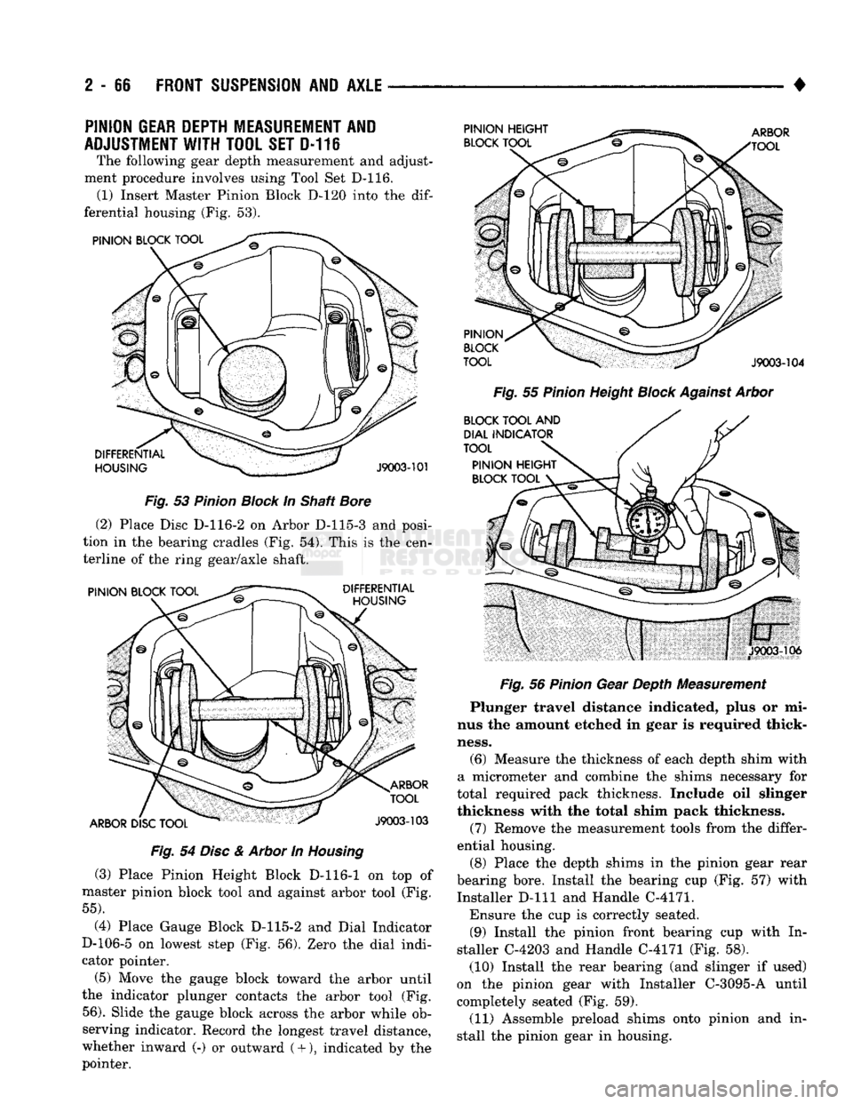
D-116 The following gear depth measurement and adjust
ment procedure involves using Tool Set D-116. (1) Insert Master Pinion Block D-120 into the
dif
ferential housing (Fig. 53).
Fig.
53
Pinion
Block
In Shaft
Bore
(2) Place Disc D-116-2 on Arbor D-115-3 and posi
tion in the bearing cradles (Fig. 54). This is the cen
terline of the ring gear/axle shaft.
Fig.
54
Disc
&
Arbor
In
Housing
(3) Place Pinion Height Block D-116-1 on top of
master pinion block tool and against arbor tool (Fig.
55).
(4) Place Gauge Block D-115-2 and Dial Indicator
D-106-5 on lowest step (Fig. 56). Zero the dial indi
cator pointer.
(5) Move the gauge block toward the arbor until
the indicator plunger contacts the arbor tool (Fig.
56).
Slide the gauge block across the arbor while ob
serving indicator. Record the longest travel distance,
whether inward (-) or outward
(
+ ), indicated by the
pointer.
Fig.
55
Pinion
Height
Block
Against
Arbor
Fig.
56
Pinion
Gear Depth Measurement
Plunger travel distance indicated, plus or mi
nus the amount etched in gear is required thick
ness.
(6) Measure the thickness of each depth shim with
a micrometer and combine the shims necessary for
total required pack thickness. Include oil slinger
thickness with the total shim pack thickness.
(7) Remove the measurement tools from the differ
ential housing.
(8) Place the depth shims in the pinion gear rear
bearing bore. Install the bearing cup (Fig. 57) with
Installer D-lll and Handle C-4171.
Ensure the cup is correctly seated. (9) Install the pinion front bearing cup with In
staller C-4203 and Handle C-4171 (Fig. 58). (10) Install the rear bearing (and slinger if used)
on the pinion gear with Installer C-3095-A until
completely seated (Fig. 59).
(11) Assemble preload shims onto pinion and in
stall the pinion gear in housing.
Page 216 of 1502
•
BRAKES
5 - 29 presses the outboard shoe lining against the opposite
side of the rotor to complete braking action.
The application or release of fluid pressure causes
only a very slight movement of the caliper and pis
ton. At brake release, the piston and caliper return
to the non-applied position.
The brakeshoes do not retract an appreciable dis
tance from the rotor. The minimal running clearance
between the lining and rotor provides improved re sponse and reduced pedal travel. It also helps in pre
venting dirt and foreign material from lodging
between the shoe and rotor surfaces.
DISC
BRAKE
LINING WEAR COMPENSATION
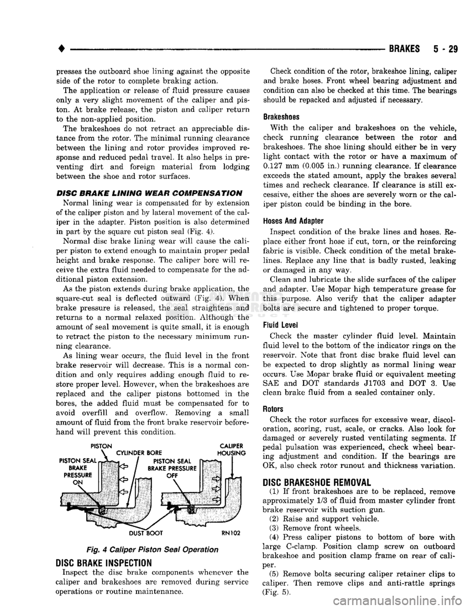
Normal lining wear is compensated for by extension
of the caliper piston and by lateral movement of the cal
iper in the adapter. Piston position is also determined
in part by the square cut piston seal (Fig. 4).
Normal disc brake lining wear will cause the cali
per piston to extend enough to maintain proper pedal height and brake response. The caliper bore will receive the extra fluid needed to compensate for the ad
ditional piston extension.
As the piston extends during brake application, the
square-cut seal is deflected outward (Fig. 4). When
brake pressure is released, the seal straightens and
returns to a normal relaxed position. Although the amount of seal movement is quite small, it is enough
to retract the piston to the necessary minimum run
ning clearance.
As lining wear occurs, the fluid level in the front
brake reservoir will decrease. This is a normal con dition and only requires adding enough fluid to restore proper level. However, when the brakeshoes are
replaced and the caliper pistons bottomed in the
bores,
the added fluid must be compensated for to avoid overfill and overflow. Removing a small
amount of fluid from the front brake reservoir before
hand will prevent this condition.
PISTON CALIPER
DUST BOOT
RN102
Fig.
4 Caliper
Piston
Seal
Operation
DISC
BRAKE INSPECTION
Inspect the disc brake components whenever the
caliper and brakeshoes are removed during service
operations or routine maintenance. Check condition of the rotor, brakeshoe lining, caliper
and brake hoses. Front wheel bearing adjustment and
condition can also be checked at this time. The bearings
should be repacked and adjusted if necessary.
Brakeshoes
With the caliper and brakeshoes on the vehicle,
check running clearance between the rotor and
brakeshoes. The shoe lining should either be in very light contact with the rotor or have a maximum of
0.127 mm (0.005 in.) running clearance. If clearance
exceeds the stated amount, apply the brakes several
times and recheck clearance. If clearance is still ex cessive, either the shoes are severely worn or the cal
iper piston could be binding in the bore.
Hoses
And Adapter Inspect condition of the brake lines and hoses. Re
place either front hose if cut, torn, or the reinforcing
fabric is visible. Check condition of the metal brake-
lines.
Replace any line that is badly rusted, leaking
or damaged in any way.
Clean and lubricate the slide surfaces of the caliper
and adapter. Use Mopar high temperature grease for
this purpose. Also verify that the caliper adapter
bolts are secure and tightened to proper torque.
Fluid Level Check the master cylinder fluid level. Maintain
fluid level to the bottom of the indicator rings on the
reservoir. Note that front disc brake fluid level can
be expected to drop slightly as normal lining wear occurs. Use Mopar brake fluid or equivalent meeting SAE and DOT standards J1703 and DOT 3. Use
clean brake fluid from a sealed container only.
Rotors
Check the rotor surfaces for excessive wear, discol
oration, scoring, rust, scale, or cracks. Also look for
damaged or severely rusted ventilating segments. If
pedal pulsation was experienced, check wheel bear ing adjustment and condition. If the bearings are OK, also check rotor runout and thickness variation.
DISC
BRAKESHOE
REMOVAL
(1) If front brakeshoes are to be replaced, remove
approximately 1/3 of fluid from master cylinder front
brake reservoir with suction gun. (2) Raise and support vehicle.
(3) Remove front wheels.
(4) Press caliper pistons to bottom of bore with
large C-clamp. Position clamp screw on outboard
brakeshoe and position clamp frame on rear of cali
per. (5) Remove bolts securing caliper retainer clips to
caliper. Then remove clips and anti-rattle springs (Fig. 5).
Page 226 of 1502
BRAKES
5 - 39
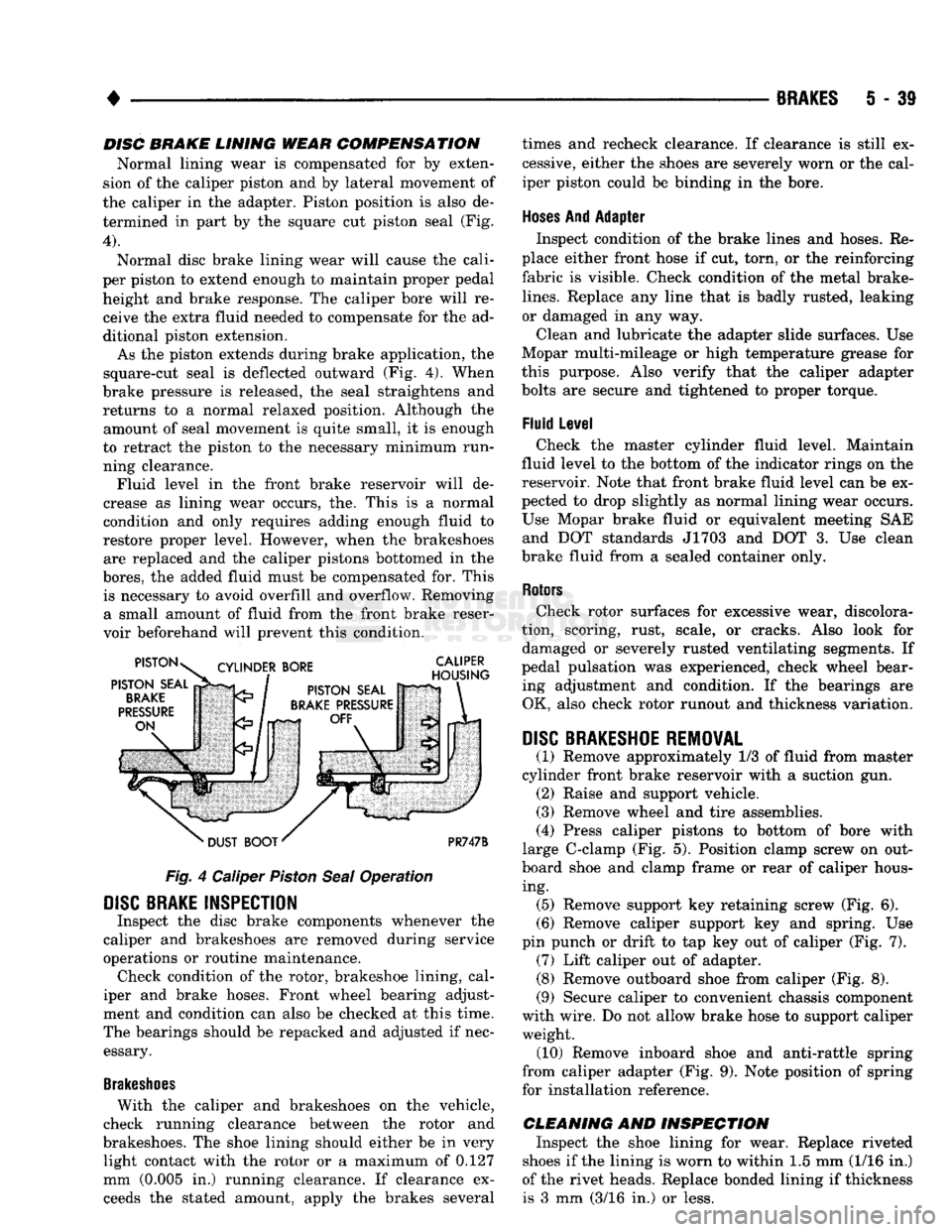
DISC BRAKE LINING WEAR COMPENSATION
Normal lining wear is compensated for by exten
sion of the caliper piston and by lateral movement of
the caliper in the adapter. Piston position is also de termined in part by the square cut piston seal (Fig.
4).
Normal disc brake lining wear will cause the cali
per piston to extend enough to maintain proper pedal height and brake response. The caliper bore will receive the extra fluid needed to compensate for the ad
ditional piston extension.
As the piston extends during brake application, the
square-cut seal is deflected outward (Fig. 4). When
brake pressure is released, the seal straightens and returns to a normal relaxed position. Although the amount of seal movement is quite small, it is enough
to retract the piston to the necessary minimum run ning clearance. Fluid level in the front brake reservoir will de
crease as lining wear occurs, the. This is a normal
condition and only requires adding enough fluid to
restore proper level. However, when the brakeshoes are replaced and the caliper pistons bottomed in the
bores,
the added fluid must be compensated for. This is necessary to avoid overfill and overflow. Removing a small amount of fluid from the front brake reser
voir beforehand will prevent this condition.
Fig.
4 Caliper
Piston
Seal
Operation
DISC
BRAKE INSPECTION
Inspect the disc brake components whenever the
caliper and brakeshoes are removed during service
operations or routine maintenance. Check condition of the rotor, brakeshoe lining, cal
iper and brake hoses. Front wheel bearing adjust
ment and condition can also be checked at this time.
The bearings should be repacked and adjusted if nec essary.
Brakeshoes
With the caliper and brakeshoes on the vehicle,
check running clearance between the rotor and
brakeshoes. The shoe lining should either be in very light contact with the rotor or a maximum of 0.127
mm (0.005 in.) running clearance. If clearance exceeds the stated amount, apply the brakes several times and recheck clearance. If clearance is still ex
cessive, either the shoes are severely worn or the cal
iper piston could be binding in the bore.
Hoses
And Adapter Inspect condition of the brake lines and hoses. Re
place either front hose if cut, torn, or the reinforcing
fabric is visible. Check condition of the metal brake-
lines.
Replace any line that is badly rusted, leaking
or damaged in any way.
Clean and lubricate the adapter slide surfaces. Use
Mopar multi-mileage or high temperature grease for
this purpose. Also verify that the caliper adapter
bolts are secure and tightened to proper torque.
Fluid Level Check the master cylinder fluid level. Maintain
fluid level to the bottom of the indicator rings on the
reservoir. Note that front brake fluid level can be ex
pected to drop slightly as normal lining wear occurs.
Use Mopar brake fluid or equivalent meeting SAE and DOT standards J1703 and DOT 3. Use clean
brake fluid from a sealed container only.
Rotors
Check rotor surfaces for excessive wear, discolora
tion, scoring, rust, scale, or cracks. Also look for damaged or severely rusted ventilating segments. If
pedal pulsation was experienced, check wheel bear ing adjustment and condition. If the bearings are OK, also check rotor runout and thickness variation.
DISC
BRAKESHOE REMOVAL
(1) Remove approximately 1/3 of fluid from master
cylinder front brake reservoir with a suction gun. (2) Raise and support vehicle.
(3) Remove wheel and tire assemblies.
(4) Press caliper pistons to bottom of bore with
large C-clamp (Fig. 5). Position clamp screw on out
board shoe and clamp frame or rear of caliper hous ing. (5) Remove support key retaining screw (Fig. 6).
(6) Remove caliper support key and spring. Use
pin punch or drift to tap key out of caliper (Fig. 7). (7) Lift caliper out of adapter. (8) Remove outboard shoe from caliper (Fig. 8).
(9) Secure caliper to convenient chassis component
with wire. Do not allow brake hose to support caliper weight. (10) Remove inboard shoe and anti-rattle spring
from caliper adapter (Fig. 9). Note position of spring
for installation reference.
CLEANING AND INSPECTION Inspect the shoe lining for wear. Replace riveted
shoes if the lining is worn to within 1.5 mm (1/16 in.)
of the rivet heads. Replace bonded lining if thickness is 3 mm (3/16 in.) or less.
Page 818 of 1502
1
•
FRAME
AND
BUMPERS
13 - 31 PIVOT BOL T ADJUSTMENT
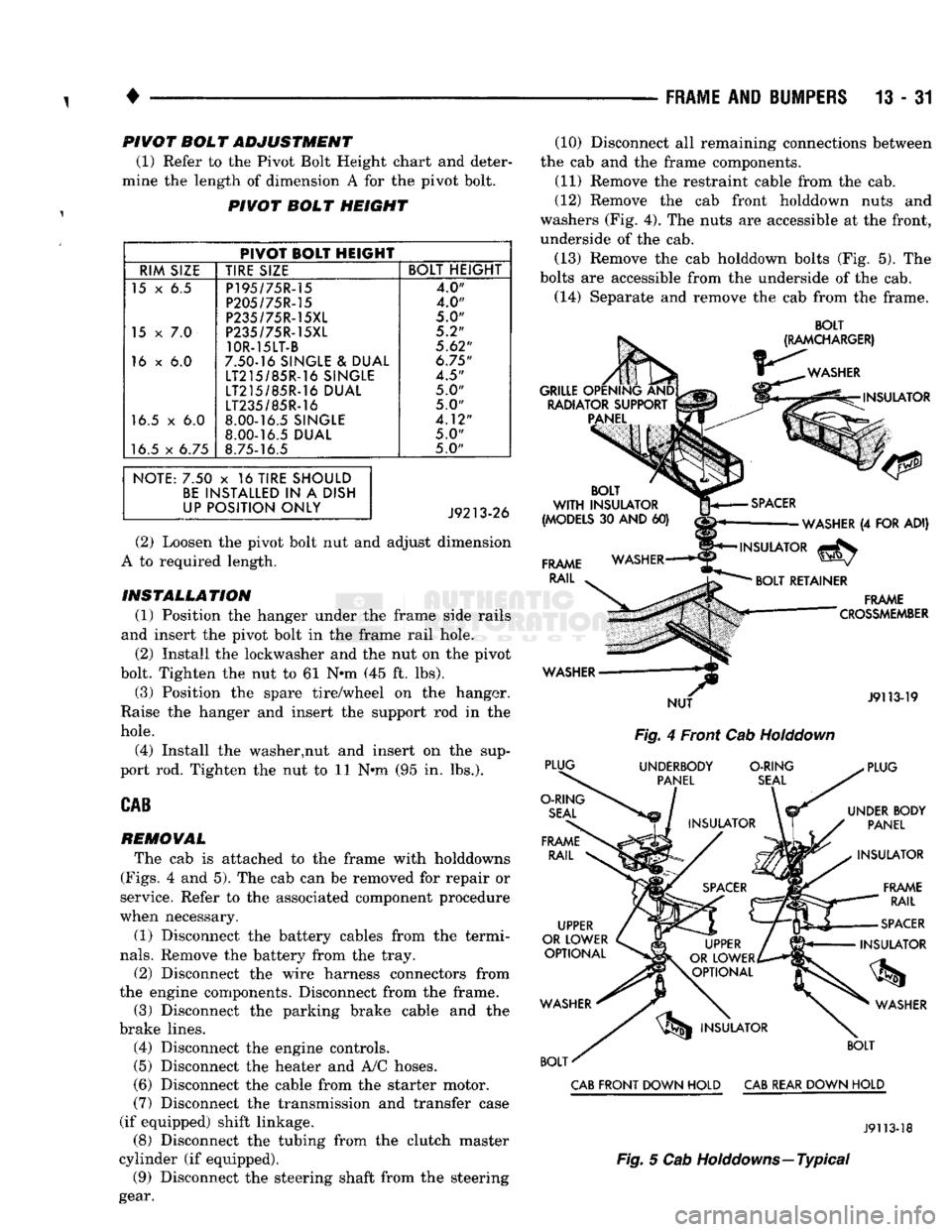
(1) Refer to the Pivot Bolt Height chart and deter
mine the length of dimension A for the pivot bolt.
PIVOT BOLT HEIGHT
PIVOT BOLT HEIGHT
RIM SIZE TIRE SIZE BOLT HEIGHT
15 x 6.5 P195/75R-15
4.0"
P205/75R-15 4.0"
P235/75R-15XL
5.0"
15
x 7.0
P235/75R-15XL 5.2"
10R-15LT-B
5.62"
16 x 6.0 7.50-16 SINGLE & DUAL
6.75"
LT215/85R-16 SINGLE
4.5"
LT215/85R-16 DUAL 5.0"
LT235/85R-16
5.0"
16.5 x 6.0 8.00-16.5 SINGLE
4.12"
8.00-16.5 DUAL
5.0"
16.5 x 6.75 8.75-16.5 5.0"
NOTE: 7.50 x 16 TIRE SHOULD BE INSTALLED IN A DISH
UP POSITION ONLY
(2) Loosen the pivot bolt nut and adjust dimension
A to required length.
INSTALLATION (1) Position the hanger under the frame side rails
and insert the pivot bolt in the frame rail hole. (2) Install the lockwasher and the nut on the pivot
bolt. Tighten the nut to 61 N*m (45 ft. lbs).
(3) Position the spare tire/wheel on the hanger.
Raise the hanger and insert the support rod in the
hole.
(4) Install the washer,nut and insert on the sup
port rod. Tighten the nut to 11 Nnn (95 in. lbs.).
CAB
REMOVAL
The cab is attached to the frame with holddowns
(Figs.
4 and 5). The cab can be removed for repair or
service. Refer to the associated component procedure
when necessary.
(1) Disconnect the battery cables from the termi
nals.
Remove the battery from the tray.
(2) Disconnect the wire harness connectors from
the engine components. Disconnect from the frame. (3) Disconnect the parking brake cable and the
brake lines. (4) Disconnect the engine controls.
(5)
Disconnect the heater and A/C hoses.
(6) Disconnect the cable from the starter motor.
(7)
Disconnect the transmission and transfer case
(if equipped) shift linkage. (8) Disconnect the tubing from the clutch master
cylinder (if equipped). (9) Disconnect the steering shaft from the steering
gear. (10) Disconnect all remaining connections between
the cab and the frame components. (11) Remove the restraint cable from the cab.
(12) Remove the cab front holddown nuts and
washers (Fig. 4). The nuts are accessible at the front,
underside of the cab.
(13) Remove the cab holddown bolts (Fig. 5). The
bolts are accessible from the underside of the cab.
(14) Separate and remove the cab from the frame.
BOLT
Fig.
4 Front Cab
Holddown
CAB
FRONT DOWN HOLD
CAB
REAR DOWN HOLD
J9113-18
Fig.
5 Cab Holddowns—Typical
Page 1071 of 1502
21
- 70
G360
TRANSMISSION OVERHAUL
•
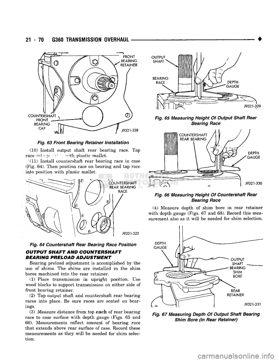
Fig.
63 Front Bearing Retainer
installation
(10) Install output shaft rear bearing race. Tap
race into
position
with plastic mallet. (11) Install countershaft rear bearing race in case
(Fig. 64). Then position race on bearing and tap race
into position with plastic mallet.
Fig.
64 Countershaft Rear Bearing
Race
Position
OUTPUT SHAFT AND COUNTERSHAFT
BEARING PRELOAD ADJUSTMENT
Bearing preload adjustment is accomplished by the
use of shims. The shims are installed in the shim
bores machined into the rear retainer. (1) Place transmission in upright position. Use
wood blocks to support transmission on either side of
front bearing retainer.
(2) Tap output shaft and countershaft rear bearing
races into place. Be sure races are seated on bear
ings.
(3) Measure distance from top each of rear bearing
race to case surface with depth gauge (Figs. 65 and
66).
Measurements reflect amount of bearing race
that extends above rear surface of case. Record these measurements as they will be needed for shim selec
tion.
Fig.
65
Measuring
Height Of Output Shaft Rear
Bearing
Race
Fig.
66
Measuring
Height Of Countershaft Rear
Bearing
Race
(4) Measure depth of shim bore in rear retainer
with depth gauge (Figs. 67 and 68). Record this mea surement also as it will be needed for shim selection.
Fig.
67
Measuring
Depth Of Output Shaft Bearing
Shim
Bore
(In Rear
Retainer)