1993 DODGE TRUCK clock setting
[x] Cancel search: clock settingPage 375 of 1502
8D
- 24
IGNITION
SYSTEMS
•
.040
GAUGE
SPARK
"PLUG
J908D-10
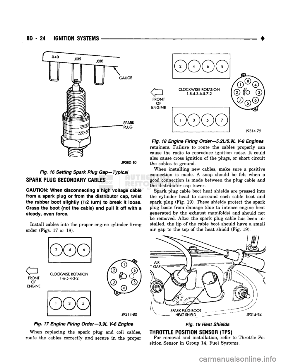
Fig.
16 Setting
Spark Plug
Gap—Typical
SPARK
PLUG
SECONDARY
CABLES
CAUTION:
When disconnecting
a
high voltage cable
from
a
spark plug
or
from
the
distributor cap, twist
the rubber boot slightly
(1/2
turn)
to
break
it
loose.
Grasp
the
boot
(not
the
cable)
and
pull
it off
with
a
steady,
even force.
Install cables into
the
proper engine cylinder firing
order (Figs.
17 or 18).
FRONT OF
ENGINE
CLOCKWISE
ROTATION
1-6-5-4-3-2
J9314-80
Fig.
17
Engine
Firing Order—3.9L V-6
Engine
When replacing
the
spark plug
and
coil cables,
route
the
cables correctly
and
secure
in the
proper a
FRONT OF
ENGINE
CLOCKWISE
ROTATION
1-8-4-3-6-5-7-2
J9314-79
Fig.
18
Engine
Firing Order—5.2U5.9L V-8
Engines
retainers. Failure
to
route
the
cables properly
can
cause
the
radio
to
reproduce ignition noise.
It
could
also cause cross ignition
of the
plugs,
or
short circuit
the cables
to
ground.
When installing
new
cables, make sure
a
positive
connection
is
made.
A
snap should
be
felt when
a
good connection
is
made between
the
plug cable
and
the distributor
cap
tower.
Spark plug cable boot heat shields
are
pressed into
the cylinder head
to
surround each cable boot
and
spark plug
(Fig. 19).
These shields protect
the
spark
plug boots from damage
(due to
intense engine heat generated
by the
exhaust manifolds)
and
should
not
be removed. After
the
spark plug cable
has
been
in
stalled,
the lip of the
cable boot should have
a
small
air
gap to the top of the
heat shield
(Fig. 19).
SPARK
PLUG BOOT
-
HEAT SHIELD
J9314-94
Fig.
19 Heat
Shields
THROTTLE
POSITION
SENSOR
(TPS) For removal
and
installation, refer
to
Throttle
Po
sition Sensor
in
Group
14,
Fuel Systems.
Page 384 of 1502
•
INSTRUMENT PANEL
AND
GAUGES
8E - 3
MALFUNCTION INDICATOR (CHECK ENGINE)
Fig.
5
Distance Sensor
If
the
input from
one of the
following sensors fails
an internal Powertrain Control Module
(PCM)
self
check,
the PCM
turns
on the
Check Engine Lamp. The
PCM
then substitutes
a
modified signal
in
place
of
the one
that failed until
a
repair
is
made:
• Manifold Absolute Pressure (MAP) Sensor
• Throttle Position Sensor
• Coolant Temperature Sensor
• Battery Voltage Sense
• Battery Voltage
Too
High
Refer
to the
appropriate Powertrain Diagnostic
Test Procedures manual
for
further information.
ELECTRONIC DIGITAL CLOCK
The electronic digital clock
is in the
radio.
The
clock
and
radio each
use the
display panel built into
the radio.
A
digital readout indicates
the
time
in
hours
and
minutes whenever
the
ignition switch
is in
the
ON or ACC
position. When
the
ignition switch
is in the OFF
position
or
when
the
radio frequency
is
being displayed, time keeping
is
accurately maintained. The procedure
for
setting
the
clock varies slightly
with each radio.
The
correct procedure
is
described under
the
individual radio operating instructions
re
ferred
to in the
Owner Manual supplied with
the ve
hicle.
MESSAGE CENTER—GAS ENGINE
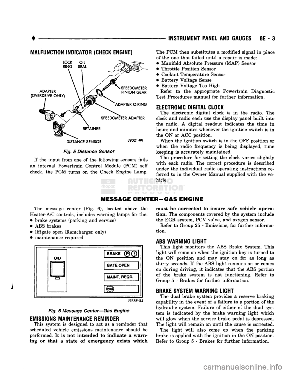
The message center
(Fig. 6),
located above
the
Heater-A/C controls, includes warning lamps
for the:
• brake systems (parking
and
service)
•
ABS
brakes • liftgate open (Ramcharger only)
• maintenance required.
O/D
BRAKE
(P)(7
GATE OPEN
MAINT
REQD.
J938E-54
Fig.
6
Message Center—Gas Engine
EMISSIONS
MAINTENANCE REMINDER
This system
is
designed
to act as a
reminder that
scheduled vehicle emissions maintenance should
be
performed.
It is not
intended
to
indicate
a
warn
ing
or
that
a
state
of
emergency exists which must
be
corrected
to
insure safe vehicle opera
tion.
The
components covered
by the
system include
the
EGR
system,
PCV
valve,
and
oxygen sensor. Refer
to
Group
25 -
Emissions,
for
further informa
tion.
ABS
WARNING
LIGHT
This light monitors
the ABS
Brake System. This
light will come
on
when
the
ignition
key is
turned
to
the
ON
position
and may
stay
on for as
long
as
thirty seconds.
If the ABS
light remains
on or
comes on during driving,
it
indicates that
the ABS
portion
of
the
brake system
is not
functioning. Refer
to
Group
5 -
Brakes
for
further information.
BRAKE
SYSTEM WARNING
LIGHT
The dual brake system provides
a
reserve braking
capability
in the
event
of a
failure
to a
portion
of the
hydraulic system. Failure
of
either
of the
dual sys
tem
is
indicated
by the
brake warning light which
will glow when
the
service brake pedal
is
depressed.
The light will remain
on
until
the
cause
is
corrected. The light will also come
on
when
the
parking
brake
is
applied with
the
ignition
in the ON
position.
Refer
to
Group
5 -
Brakes
for
further information.
Page 1141 of 1502
21
• 140
IN-VEHICLE
SERVICE-32RH/36RH/37RH/42RH/46RH
•
VALVE BODY CONTROL
PRESSURE
ADJUSTMENTS
There
are two
control pressure adjustments
on the
valve body which
are:
Line pressure
and
throttle pres
sure.
The valve body must
be
removed from
the
transmission
in
order
to
perform
the
adjust
ments. Refer
to the
valve body removal/installa
tion procedures
in
this section. Because line
and
throttle pressures
are
interdepen
dent (each affects shift quality
and
timing), both
ad
justments must
be
performed properly
and in the
correct sequence. Adjust line pressure first
and
throt
tle pressure last.
LINE
PRESSURE
ADJUSTMENT
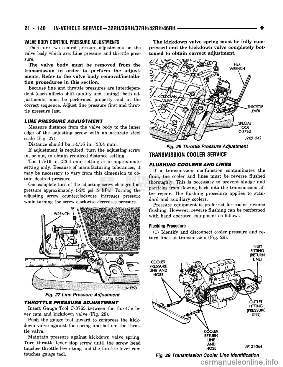
Measure distance from
the
valve body
to the
inner
edge
of the
adjusting screw with
an
accurate steel scale
(Fig. 27).
Distance should
be 1-5/16 in. (33.4 mm).
If adjustment
is
required, turn
the
adjusting screw
in,
or out, to
obtain required distance setting.
The
1-5/16 in. (33.4 mm)
setting
is an
approximate
setting only. Because
of
manufacturing tolerances,
it
may
be
necessary
to
vary from this dimension
to ob
tain desired pressure.
One complete turn
of the
adjusting screw changes line
pressure approximately
1-2/3 psi (9 kPa).
Turning
the
adjusting screw counterclockwise increases pressure
while turning
the
screw clockwise decreases pressure.
RH258
Fig.
27
Line
Pressure
Adjustment
THROTTLE
PRESSURE
ADJUSTMENT
Insert Gauge Tool C-3763 between
the
throttle
le
ver
cam and
kickdown valve
(Fig. 28).
Push
the
gauge tool inward
to
compress
the
kick-
down valve against
the
spring
and
bottom
the
throt
tle valve. Maintain pressure against kickdown valve spring.
Turn throttle lever stop screw until
the
screw head touches throttle lever tang
and the
throttle lever
cam
touches gauge tool. The kickdown valve spring must
be
fully com
pressed
and the
kickdown valve completely bot
tomed
to
obtain correct adjustment.
HEX
WRENCH
^
KICKDOWN
yL£_
THROTTLE
LEVER
SPECIAL
" TOOL C-3763
J9121-542
Fig.
28
Throttle
Pressure
Adjustment
TRANSMISSION
COOLER
SERVICE
FLUSHING
COOLERS
AND
LINES
If
a
transmission malfunction contaminates
the
fluid, the cooler
and
lines must
be
reverse flushed
thoroughly. This
is
necessary
to
prevent sludge
and
particles from flowing back into
the
transmission
af
ter repair.
The
flushing procedure applies
to
standard
and
auxiliary coolers.
Pressure equipment
is
preferred
for
cooler reverse
flushing. However, reverse flushing
can be
performed with hand operated equipment
as
follows.
Flushing
Procedure (1) Identify
and
disconnect cooler pressure
and re
turn lines
at
transmission
(Fig. 29).
INLET
FITTING
(RETURN
_ LINE)
COOLER
^
PRESSURE
LINE
AND
HOSE OUTLET
FITTING
(PRESSURE LINE)
COOLER RETURN LINE
AND
HOSE
J9121-364
Fig.
29
Transmission
Cooler
Line
Identification
Page 1185 of 1502
21 - 184
TRANSMISSION
OVERHAUL—32RH
-
Fig. 110 Line Pressure Adjustment—32RH
Throttle
Pressure
Adjustment
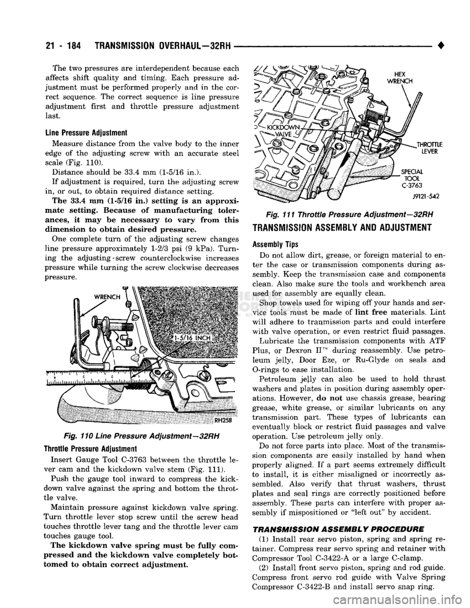
Insert Gauge Tool C-3763 between the throttle le
ver cam and the kickdown valve stem (Fig. 111).
Push the gauge tool inward to compress the kick-
down valve against the spring and bottom the throt
tle valve.
Maintain pressure against kickdown valve spring.
Turn throttle lever stop screw until the screw head
touches throttle lever tang and the throttle lever cam
touches gauge tool.
The kickdown valve spring must be fully com
pressed and the kickdown valve completely bot
tomed to obtain correct adjustment.
•
Fig. 111 Throttle Pressure Adjustment—32RH
TRANSMISSION ASSEMBLY AND ADJUSTMENT
Assembly
Tips
Do not allow dirt, grease, or foreign material to en
ter the case or transmission components during as sembly. Keep the transmission case and components
clean. Also make sure the tools and workbench area
used for assembly are equally clean.
Shop towels used for wiping off your hands and ser
vice tools must be made of lint free materials. Lint
will adhere to tranmission parts and could interfere with valve operation, or even restrict fluid passages.
Lubricate the transmission components with ATF
Plus,
or Dexron II™ during reassembly. Use petro leum jelly, Door Eze, or Ru-Glyde on seals and O-rings to ease installation.
Petroleum jejly can also be used to hold thrust
washers and plates in position during assembly oper ations. However, do not use chassis grease, bearing
grease, white grease, or similar lubricants on any
transmission part. These types of lubricants can eventually block or restrict fluid passages and valve
operation. Use petroleum jelly only.
Do not force parts into place. Most of the transmis
sion components are easily installed by hand when
properly aligned. If a part seems extremely difficult
to install, it is either misaligned or incorrectly as sembled. Also verify that thrust washers, thrust
plates and seal rings are correctly positioned before assembly. These parts can interfere with proper as
sembly if mispositioned or "left out" by accident.
TRANSMISSION
ASSEMBLY PROCEDURE (1) Install rear servo piston, spring and spring re
tainer. Compress rear servo spring and retainer with Compressor Tool C-3422-A or a large C-clamp.
(2) Install front servo piston, spring and rod guide.
Compress front servo rod guide with Valve Spring
Compressor C-3422-B and install servo snap ring.
The two pressures are interdependent because each
affects shift quality and timing. Each pressure ad
justment must be performed properly and in the cor rect sequence. The correct sequence is line pressure adjustment first and throttle pressure adjustment
last.
Line
Pressure
Adjustment
Measure distance from the valve body to the inner
edge of the adjusting screw with an accurate steel
scale (Fig. 110).
Distance should be 33.4 mm (1-5/16 in.).
If adjustment is required, turn the adjusting screw
in, or out, to obtain required distance setting.
The 33.4 mm (1-5/16 in,) setting Is an approxi
mate setting. Because of manufacturing toler
ances,
it may be necessary to vary from this
dimension to obtain desired pressure.
One complete turn of the adjusting screw changes
line pressure approximately 1-2/3 psi (9 kPa). Turn
ing the adjusting-screw counterclockwise increases
pressure while turning the screw clockwise decreases
pressure.
Page 1224 of 1502
•
TRANSMISSION
OVERHAUL—36RH/37RH
21 - 223 (16) Align and install governor plug end plate
(Fig. 99) on valve body and install end plate screws.
Tighten screws to 4 N»m (35 in. lbs.) torque.
(17) Install manual valve (Fig. 99). (18) Install throttle valve and spring. Then install
kickdown valve and detent (Fig. 99). (19) Install pressure regulator valve and switch
valve (Fig. 99).
(20) Install manual lever detent spring in housing.
Place detent ball on end of spring and push ball and spring into housing. Secure ball and spring with Re
tainer Tool 6583 (Fig. 88).
(21) Insert line pressure adjusting screw in adjust
ing screw bracket (Fig. 92).
(22) Place valve spring on end of line pressure reg
ulator valve.
(23) Install switch valve spring on tang at end of
adjusting screw bracket (Fig. 87). (24) Install adjusting screw bracket on valve body.
Align springs, press bracket toward valve body and install long bottom bracket attaching screw first. Do
not tighten screw fully at this time.
(25) Carefully align bracket on valve body and
transfer plate and install remaining (two) bracket screws. Verify that valve springs and bracket are
properly aligned. Then tighten all three bracket screws to 4 N*m (35 in. lbs.) torque.
(26) Install throttle lever in valve body. Then in
stall manual lever over throttle lever and start man
ual lever into valve body.
(27) Align manual lever detent with detent ball
and align lever arm with manual valve. Hold throt
tle lever upward. Then press down on manual lever until lever is fully seated.
(28) Install manual lever seal, washer and retain
ing E-clip.
(29) Lubricate shaft of manual lever with light
coat of petroleum jelly. This will help protect seal lip
when manual shaft seal is installed.
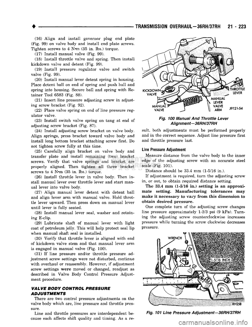
(30) Verify that throttle lever is aligned with end
of kickdown valve stem and that manual lever arm
is engaged in manual valve (Fig. 100).
(31) If line pressure and/or throttle pressure ad
justment screw settings were not disturbed, continue with overhaul or reassembly. However, if adjustment screw settings were moved or changed, readjust as
described in Valve Body Control Pressure Adjust
ment procedure.
VALVE BODY CONTROL
PRESSURE
ADJUSTMENTS
There are two control pressure adjustments on the
valve body which are, line pressure and throttle pres
sure.
Line and throttle pressures are interdependent be
cause each affects shift quality and timing. As a re-
Fig.
100 Manual And
Throttle
Lever
Alignment-36RH/37RH
suit, both adjustments must be performed properly
and in the correct sequence. Adjust line pressure first
and throttle pressure last.
Line
Pressure
Adjustment Measure distance from the valve body to the inner
edge of the adjusting screw with an accurate steel scale (Fig. 101).
Distance should be 33.4 mm (1-5/16 in.).
If adjustment is required, turn the adjusting screw
in, or out, to obtain required distance setting. The 33.4 mm (1-5/16 in.) setting is an approxi
mate setting. Manufacturing tolerances may
make it necessary to vary from this dimension to obtain desired pressure.
One complete turn of the adjusting screw changes
line pressure approximately 1-2/3 psi (9 kPa). Turn
ing the adjusting screw counterclockwise increases
pressure while turning the screw clockwise decreases
pressure.
Fig.
101
Line
Pressure
Adjustment—36RH/37RH
Page 1270 of 1502
•
TRANSMISSION
OVERHAUL-42RH
21 - 269 must be performed properly and in the correct se
quence. Line pressure is adjusted first and throttle
pressure is adjusted last.
Line
Pressure
Adjustment
Measure distance from the valve body to the inner
edge of the adjusting screw with an accurate steel
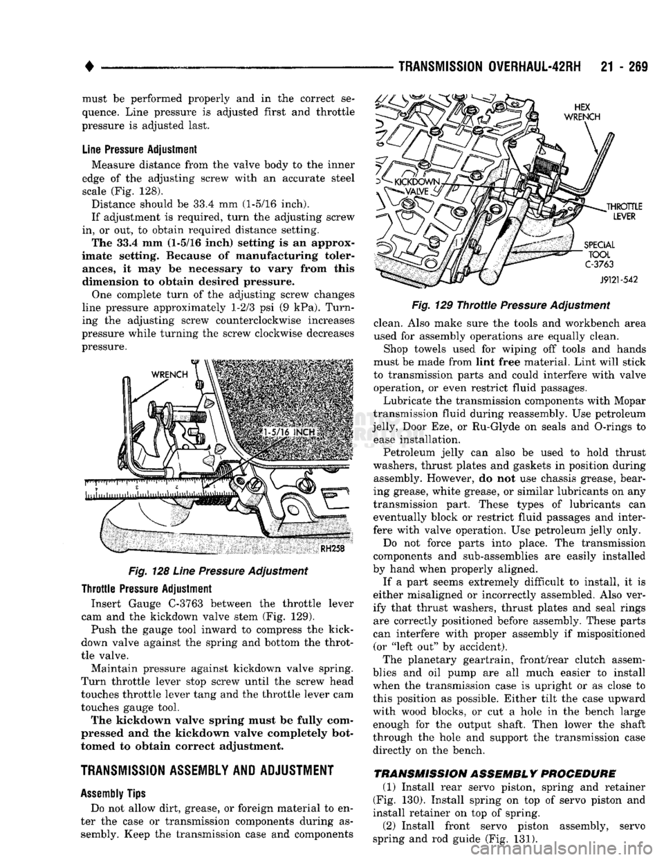
scale (Fig. 128).
Distance should be 33.4 mm (1-5/16 inch).
If adjustment is required, turn the adjusting screw
in, or out, to obtain required distance setting. The 33.4 mm (1-5/16 inch) setting is an approx
imate setting. Because of manufacturing toler
ances,
it may be necessary to vary from this
dimension to obtain desired pressure.
One complete turn of the adjusting screw changes
line pressure approximately 1-2/3 psi (9 kPa). Turn
ing the adjusting screw counterclockwise increases
pressure while turning the screw clockwise decreases
pressure.
Fig.
128
Line
Pressure
Adjustment
Throttle
Pressure
Adjustment Insert Gauge C-3763 between the throttle lever
cam and the kickdown valve stem (Fig. 129).
Push the gauge tool inward to compress the kick-
down valve against the spring and bottom the throt
tle valve.
Maintain pressure against kickdown valve spring.
Turn throttle lever stop screw until the screw head
touches throttle lever tang and the throttle lever cam
touches gauge tool.
The kickdown valve spring must be fully com
pressed and the kickdown valve completely bot
tomed to obtain correct adjustment.
TRANSMISSION ASSEMBLY AND ADJUSTMENT
Assembly
Tips
Do not allow dirt, grease, or foreign material to en
ter the case or transmission components during as sembly. Keep the transmission case and components
Fig.
129
Throttie
Pressure
Adjustment
clean. Also make sure the tools and workbench area
used for assembly operations are equally clean.
Shop towels used for wiping off tools and hands
must be made from lint free material. Lint will stick
to transmission parts and could interfere with valve operation, or even restrict fluid passages.
Lubricate the transmission components with Mopar
transmission fluid during reassembly. Use petroleum
jelly, Door Eze, or Ru-Glyde on seals and O-rings to ease installation.
Petroleum jelly can also be used to hold thrust
washers, thrust plates and gaskets in position during assembly. However, do not use chassis grease, bear
ing grease, white grease, or similar lubricants on any
transmission part. These types of lubricants can eventually block or restrict fluid passages and inter
fere with valve operation. Use petroleum jelly only.
Do not force parts into place. The transmission
components and sub-assemblies are easily installed
by hand when properly aligned.
If a part seems extremely difficult to install, it is
either misaligned or incorrectly assembled. Also ver
ify that thrust washers, thrust plates and seal rings are correctly positioned before assembly. These parts
can interfere with proper assembly if mispositioned (or "left out" by accident).
The planetary geartrain, front/rear clutch assem
blies and oil pump are all much easier to install
when the transmission case is upright or as close to
this position as possible. Either tilt the case upward
with wood blocks, or cut a hole in the bench large enough for the output shaft. Then lower the shaft
through the hole and support the transmission case
directly on the bench.
TRANSMISSION ASSEMBLY PROCEDURE
(1) Install rear servo piston, spring and retainer
(Fig. 130). Install spring on top of servo piston and
install retainer on top of spring.
(2) Install front servo piston assembly, servo
spring and rod guide (Fig. 131).
Page 1315 of 1502
21
- 314
TRANSMISSION
OVERHAUL-46RH
—
•
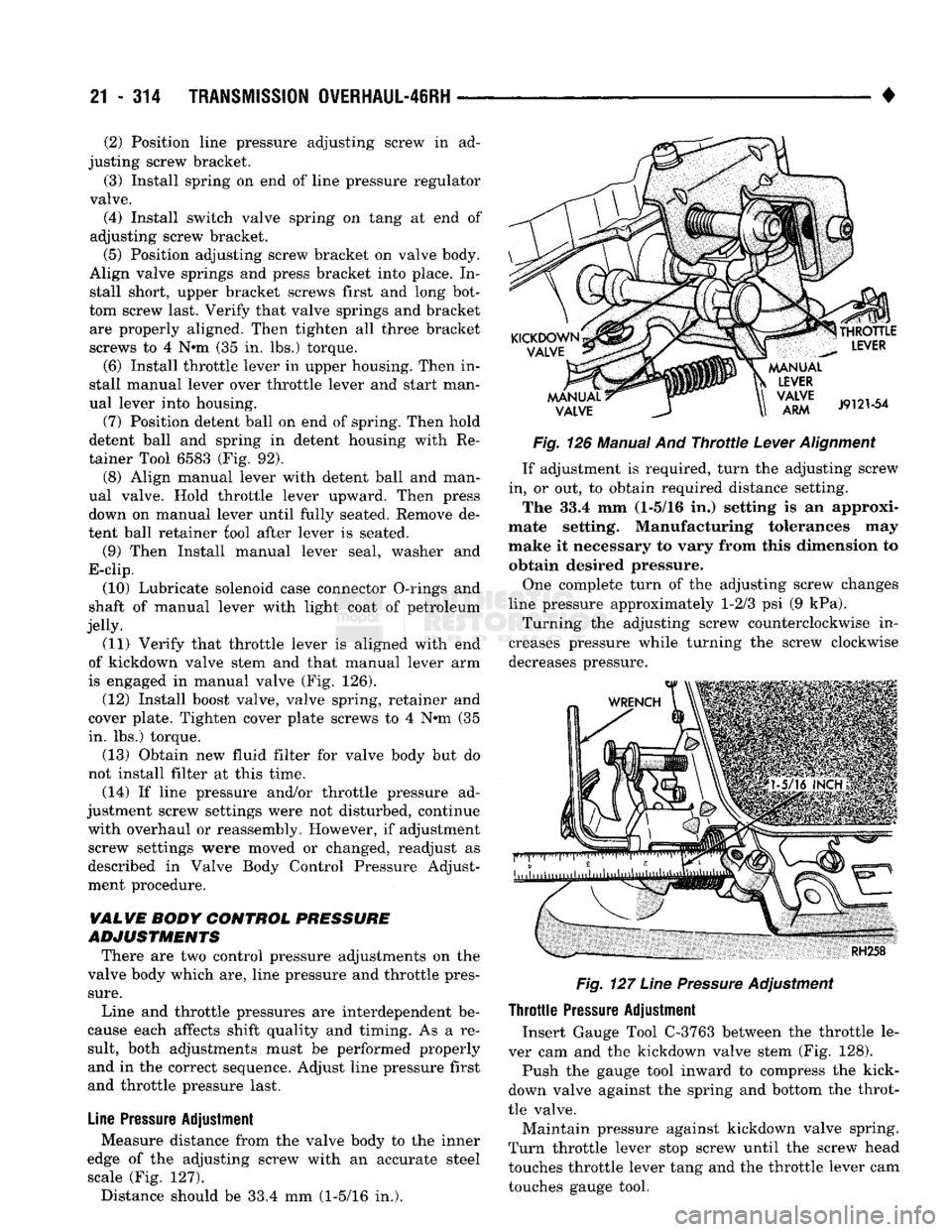
Fig.
126 Manual And
Throttle
Lever
Alignment
If adjustment is required, turn the adjusting screw
in, or out, to obtain required distance setting. The 33.4 mm (1-5/16 in.) setting is an approxi
mate setting. Manufacturing tolerances may
make it necessary to vary from this dimension to obtain desired pressure.
One complete turn of the adjusting screw changes
line pressure approximately 1-2/3 psi (9 kPa). Turning the adjusting screw counterclockwise in
creases pressure while turning the screw clockwise
decreases pressure.
Fig.
127
Line
Pressure
Adjustment
Throttle
Pressure
Adjustment Insert Gauge Tool C-3763 between the throttle le
ver cam and the kickdown valve stem (Fig. 128).
Push the gauge tool inward to compress the kick-
down valve against the spring and bottom the throt
tle valve.
Maintain pressure against kickdown valve spring.
Turn throttle lever stop screw until the screw head
touches throttle lever tang and the throttle lever cam
touches gauge tool.
(2) Position line pressure adjusting screw in ad
justing screw bracket.
(3) Install spring on end of line pressure regulator
valve. (4) Install switch valve spring on tang at end of
adjusting screw bracket. (5) Position adjusting screw bracket on valve body.
Align valve springs and press bracket into place. In stall short, upper bracket screws first and long bot
tom screw last. Verify that valve springs and bracket are properly aligned. Then tighten all three bracket
screws to 4 N*m (35 in. lbs.) torque.
(6) Install throttle lever in upper housing. Then in
stall manual lever over throttle lever and start man
ual lever into housing.
(7) Position detent ball on end of spring. Then hold
detent ball and spring in detent housing with Re
tainer Tool 6583 (Fig. 92). (8) Align manual lever with detent ball and man
ual valve. Hold throttle lever upward. Then press
down on manual lever until fully seated. Remove de
tent ball retainer fool after lever is seated.
(9) Then Install manual lever seal, washer and
E-clip.
(10) Lubricate solenoid case connector O-rings and
shaft of manual lever with light coat of petroleum
jelly. (11) Verify that throttle lever is aligned with end
of kickdown valve stem and that manual lever arm
is engaged in manual valve (Fig. 126).
(12) Install boost valve, valve spring, retainer and
cover plate. Tighten cover plate screws to 4 N»m (35
in. lbs.) torque.
(13) Obtain new fluid filter for valve body but do
not install filter at this time.
(14) If line pressure and/or throttle pressure ad
justment screw settings were not disturbed, continue with overhaul or reassembly. However, if adjustment screw settings were moved or changed, readjust as
described in Valve Body Control Pressure Adjust
ment procedure.
VALVE
BODY
CONTROL
PRESSURE
ADJUSTMENTS
There are two control pressure adjustments on the
valve body which are, line pressure and throttle pres
sure.
Line and throttle pressures are interdependent be
cause each affects shift quality and timing. As a re
sult, both adjustments must be performed properly and in the correct sequence. Adjust line pressure first
and throttle pressure last.
Line
Pressure
Adjustment Measure distance from the valve body to the inner
edge of the adjusting screw with an accurate steel scale (Fig. 127). Distance should be 33.4 mm (1-5/16 in.).