1993 DODGE TRUCK parking brake
[x] Cancel search: parking brakePage 15 of 1502
10 INTRODUCTION
•
INTERNATIONAL CONTROL AND DISPLAY SYMBOLS
ID
HIGH
BEAM P
FOG UGHTS -&
HEADLIGHTS,
PARKING UGHTS, PANEL UGHTS TURN SIGNAL A
HAZARD WARNING WINDSHIELD
WASHER
WINDSHIELD WIPER WINDSHIELD WIPER
AND WASHER
AND DEFROSTING *
VENTILATING
FAN 8
M f
REAR
WINDOW DEFOGGER
sp
REARWINLX)W WIPER
CD
l
m
REAR
WINDOW WASHER FUEL ENGINE COOLANT
TEMPERATURE BATTERY CHARGING
CONDITION ENGINE OIL
SEAT
BELT
(©) (®) ky
11 J
LIGHTER
BRAKE
FAILURE
PARKING
BRAKE
FRONT HOOD
REAR
HOOD
(TRUNK)
HORN
11 J
LIGHTER
93IN-9
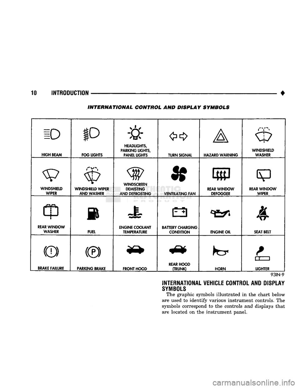
INTERNATIONAL VEHICLE CONTROL AND DISPLAY
SYMBOLS
The graphic symbols illustrated in the chart below
are used to identify various instrument controls. The
symbols correspond to the controls and displays that are located on the instrument panel.
Page 26 of 1502

CHASSIS LUBRICATION
For light
duty
cycle
vehicles
GVW resting
of
3 855 Kg (8,500 lbs ) and
below.
Component
Truck Models
Fittings
Service Interval Lubricant
Center Link
AD1
AD2
AD
4
2
36
000
km
(22,500
miles)
or 2
years Multi-purpose grease
-
NGLI
grade
2
EP
(Multi-Mileage Lubricant)
Drag
Link
Bali
joints
AW1 AW 2
AW
8
2
12
000
km
(7,500
miles)
or 6
months Multi-purpose grease
-
NGLI
grade
2
EP
(Multi-Mileage Lubricant)
Gearshift
Mechanism
Overdrive
4
AD1
1
36
000
km
(22,500
miles)
or 2
years Multi-purpose grease
-
NGLI
grade
2
EP
(Multi-Purpose Lubricant)
Parking Brake Ratio
Lever
Pivot
AD1 AD
2 AD 4
AW1 AW 8
—
36
000
km
(22,500
miles)
or 2
years
Multi-purpose grease
-
NGLI
grade
2
EP
(Multi-Purpose Lubricant)
Propeller Shaft
U-joint
AW1
AW2
AW 8
3
(1
Piece
rear
P/shaft)
12
000
km
(7,500
miles)
or 6
months
Multi-purpose grease
-
NGLI
grade
2
EP
(Multi-Purpose Lubricant)
Propeller Shaft
Slip
Spline
AD1 AD
2
(2
piece P/shaft)
1
36
000
km
(22,500
miles)
or 2
years. For severe
service,
every
4
800
km
(3,000
miles)
or 3
months. Daily,
if
vehicle is operated in
water
Multi-purpose grease
-
NGLI
grade
2
EP
(Multi-Purpose Lubricant)
Suspension
Ball Joints
AD1 AD
2
4
36
000
km
(22,500
miles) or 2 years
—
every
engine
oil change
for
off-highway operation Multi-purpose grease
-
NGLI
grade
2
EP
(Multi-Mileage Lubricant)
Tie Rod Ball Joints
AD1
AD2
AD4
AW1 AW
2
AW8 4
2
36
000
km
(22,500
miles)
or 2
years
12
000
km
(7,500
miles)
or 6
months. Daily,
if
vehicle is operated in
water
Multi-purpose grease
-
NGLI
grade
2
EP
(Multi-Mileage Lubricant)
NP-241 Transfer
Case
Shift
Lever Pivot
AW1
AW2
AW8
—
As
Required
Multi-purpose grease
-
NGLI
grade
2
EP
(Multi-Purpose Lubricant)
Wheel
Stop
AD1 AD
2
AD4
—
36
000
km
(22,500
miles)
or
as
required
Wax Type Lubricant
Constant
Velocity Joint
(Front
P/shaft)
AW1
AW2
AW8 1
12
000
km
(7,500
miles) Multi-purpose grease
-
NGLI
grade
2
EP
(Multi-Purpose Lubricant)
>
J9000-59
>
Page 28 of 1502
•
LUBRICATION AND MAINTENANCE
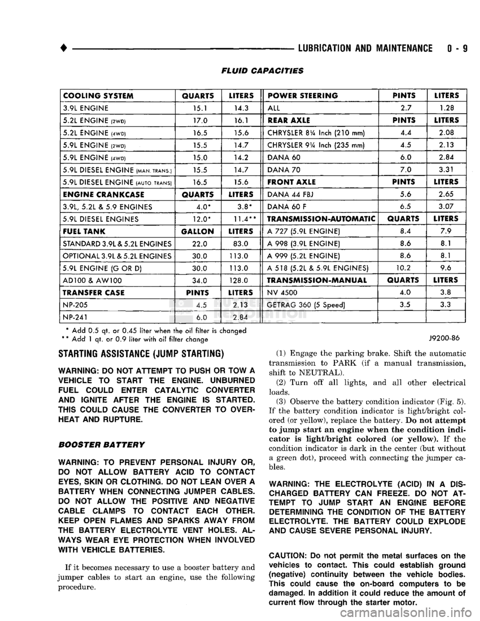
0 - 9 FLUID CAPACITIES
COOLING SYSTEM
QUARTS
LITERS
POWER STEERING PINTS
LITERS
3.9L ENGINE 15.1 14.3
ALL
2.7
1.28
5.2L ENGINE
(2WD)
17.0 16.1
REAR
AXLE
PINTS
LITERS
5.2L ENGINE
(4WD)
16.5 15.6
CHRYSLER
BVa
Inch
(210
mm) 4.4
2.08
5.9L ENGINE
(2WD)
15.5 14.7
CHRYSLER
9Va
Inch
(235
mm) 4.5
2.13
5.9L ENGINE
(4WD)
15.0 14.2
DANA
60 6.0
2.84
5.9L DIESEL ENGINE (MAN.TRANS.) 15.5 14.7
DANA
70 7.0
3.31
5.9L DIESEL ENGINE
(AUTO,
TRANS)
16.5 15.6
FRONT AXLE
PINTS
LITERS
ENGINE
CRANKCASE
QUARTS
LITERS
DANA
44
FBJ 5.6
2.65
3.9L,
5.2L & 5.9
ENGINES 4.0* 3.8*
DANA
60 F
6.5
3.07
5.9L DIESEL ENGINES 12.0*
11.4**
TRANSMISSION-AUTOMATIC
QUARTS
LITERS
FUEL TANK GALLON
LITERS
A
727 (5.9L
ENGINE) 8.4
7.9
STANDARD
3.9L & 5.2L ENGINES 22.0 83.0
A
998 (3.9L
ENGINE) 8.6
8.1
OPTIONAL 3.9L & 5.2L ENGINES 30.0 113.0
A
999 (5.2L
ENGINE) 8.6
8.1
5.9L ENGINE
{G
OR
D)
30.0 113.0
A
518 (5.2L & 5.9L
ENGINES) 10.2
9.6
AD 100
&
AW 100 34.0 128.0
TRANSMISSION-MANUAL
QUARTS
LITERS
TRANSFER
CASE
PINTS
LITERS
NV
4500
4.0
3.8
NP-205
4.5 2.13
GETRAG
360 (5
Speed)
3.5
3.3
NP-241
6.0
2.84
* Add
0.5 qt. or 0.45
liter
when
the oil filter
is
changed
*
*
Add
1 qt. or 0.9
liter
with
oil filter
change STARTING ASSISTANCE (JUMP STARTING)
WARNING:
DO NOT
ATTEMPT
TO
PUSH
OR
TOW
A
VEHICLE
TO
START
THE
ENGINE. UNBURNED FUEL COULD ENTER CATALYTIC CONVERTER
AND IGNITE AFTER
THE
ENGINE
IS
STARTED.
THIS COULD CAUSE
THE
CONVERTER
TO
OVER HEAT AND RUPTURE.
BOOSTER BATTERY
WARNING:
TO
PREVENT PERSONAL INJURY
OR,
DO
NOT
ALLOW BATTERY ACID
TO
CONTACT
EYES,
SKIN
OR
CLOTHING.
DO NOT
LEAN OVER
A
BATTERY WHEN CONNECTING JUMPER
CABLES.
DO
NOT
ALLOW
THE
POSITIVE
AND
NEGATIVE
CABLE
CLAMPS
TO
CONTACT EACH OTHER.
KEEP
OPEN FLAMES
AND
SPARKS
AWAY FROM
THE BATTERY ELECTROLYTE VENT HOLES.
AL
WAYS
WEAR
EYE
PROTECTION WHEN INVOLVED
WITH
VEHICLE BATTERIES.
If it becomes necessary to use a booster battery and
jumper cables to start an engine, use the following procedure.
J9200-86
(1) Engage the parking brake. Shift the automatic
transmission to PARK (if a manual transmission, shift to NEUTRAL).
(2) Turn off all lights, and all other electrical
loads.
(3)
Observe the battery condition indicator (Fig. 5).
If the battery condition indicator is light/bright col
ored (or yellow), replace the battery. Do not attempt
to jump start an engine when the condition indi
cator is light/bright colored (or yellow). If the
condition indicator is dark in the center (but without a green dot), proceed with connecting the jumper ca
bles.
WARNING:
THE
ELECTROLYTE (ACID)
IN A
DIS
CHARGED
BATTERY
CAN
FREEZE.
DO NOT AT
TEMPT
TO
JUMP START
AN
ENGINE BEFORE DETERMINING
THE
CONDITION
OF THE
BATTERY
ELECTROLYTE.
THE
BATTERY COULD EXPLODE
AND CAUSE SEVERE PERSONAL INJURY.
CAUTION:
Do not
permit
the
metal
surfaces
on the
vehicles
to
contact.
This
could
establish
ground
(negative)
continuity
between
the
vehicle
bodies.
This
could
cause
the
on-board
computers
to be
damaged.
In
addition
it
could
reduce
the
amount
of
current
flow
through
the
starter
motor.
Page 42 of 1502
•
LUBRICATION
AND
MAINTENANCE
0 - 23 GEAR SHIFTER BOOTS
Inspect the shifter boots periodically for stone and
heat damage. Replace, if necessary.
SEVERE DRIVING CONDITIONS The interval between the transmission drain and
refill maintenance should be decreased to:
• NV4500 manual transmission—every 29 000 km (18,000 miles)
• Automatic transmission—every 19 000 km (12,000
miles)
A severe driving condition includes:
• Extended operation with heavy cargo loads
• Driving in deep mud or snow
• Off-road operation (4WD)
• Trailer towing
• Operation as a commercial vehicle
• Snow plowing
MANUAL TRANSMISSIONS
INSPECTION/LUBE
OIL
LEVEL
The transmission should be checked for leaks when
other service is necessary under the vehicle. To check
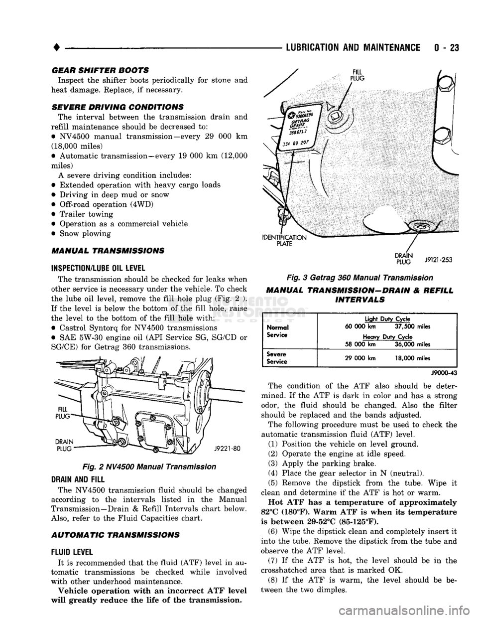
the lube oil level, remove the fill hole plug (Fig. 2 ). If the level is below the bottom of the fill hole, raise
the level to the bottom of the fill hole with:
• Castrol Syntorq for NV4500 transmissions
• SAE 5W-30 engine oil (API Service SG, SG/CD or
SG/CE) for Getrag 360 transmissions.
Fig.
2 NV4500 Manual
Transmission
DRAIN
AND
FILL
The NV4500 transmission fluid should be changed
according to the intervals listed in the Manual
Transmission—Drain & Refill Intervals chart below.
Also,
refer to the Fluid Capacities chart.
AUTOMATIC TRANSMISSIONS
FLUID
LEWEL
It is recommended that the fluid (ATF) level in au
tomatic transmissions be checked while involved
with other underhood maintenance.
Vehicle operation with an incorrect ATF level
will greatly reduce the life of the transmission.
Fig.
3 Getrag 360 Manual
Transmission
MANUAL TRANSMISSION-DRAIN & REFILL INTERVALS
Normal
Service
Light
Duty
Cycle
60 000
km
37,500
miles
Heavy
Duty
Cycle
58 000
km
36,000
miles
Severe
Service
29 000
km
18,000
miles
J9000-43
The condition of the ATF also should be deter
mined. If the ATF is dark in color and has a strong odor, the fluid should be changed. Also the filter should be replaced and the bands adjusted.
The following procedure must be used to check the
automatic transmission fluid (ATF) level.
(1) Position the vehicle on level ground.
(2) Operate the engine at idle speed.
(3) Apply the parking brake.
(4) Place the gear selector in N (neutral).
(5) Remove the dipstick from the tube. Wipe it
clean and determine if the ATF is hot or warm.
Hot ATF has a temperature of approximately
82°C (180°F). Warm ATF is when its temperature
is between 29-52°C (85-125°F). (6) Wipe the dipstick clean and completely insert it
into the tube. Remove the dipstick from the tube and
observe the ATF level.
(7) If the ATF is hot, the level should be in the
crosshatched area that is marked OK.
(8) If the ATF is warm, the level should be be
tween the two dimples.
Page 50 of 1502
•
LUBRICATION
AND
MAINTENANCE
0 - 31
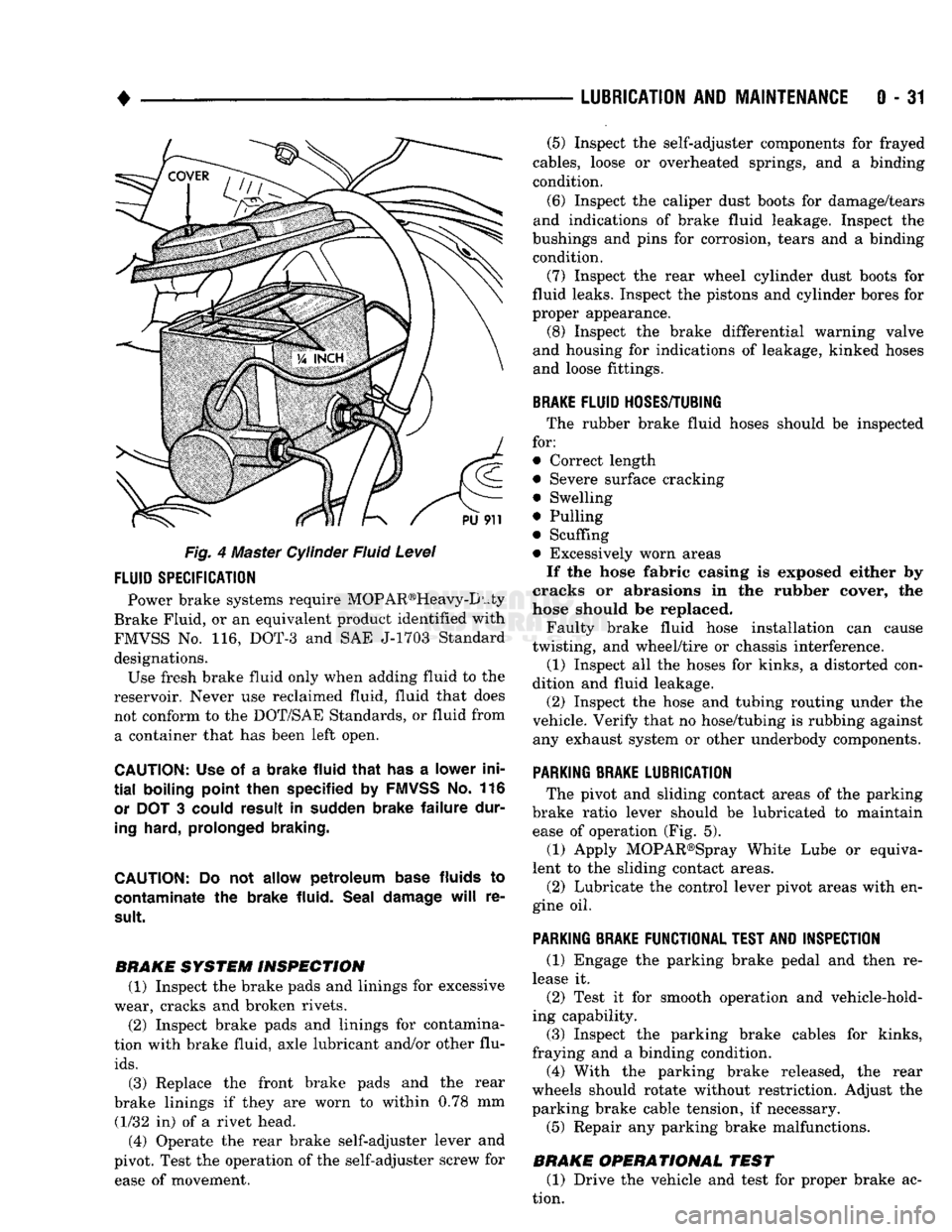
Fig. 4 Master Cylinder Fluid Level
FLUID
SPECIFICATION
Power brake systems require MOP AR®Heavy-D uty
Brake Fluid, or an equivalent product identified with
FMVSS No. 116, DOT-3 and SAE J-1703 Standard designations. Use fresh brake fluid only when adding fluid to the
reservoir. Never use reclaimed fluid, fluid that does not conform to the DOT/SAE Standards, or fluid from a container that has been left open.
CAUTION:
Use of a
brake fluid that
has a
lower ini
tial
boiling point then specified
by
FMVSS
No. 116
or
DOT 3
could result
in
sudden brake failure dur
ing
hard, prolonged braking.
CAUTION:
Do not
allow petroleum base
fluids
to
contaminate
the
brake fluid. Seal damage
will
re
sult.
BRAKE SYSTEM INSPECTION (1) Inspect the brake pads and linings for excessive
wear, cracks and broken rivets.
(2) Inspect brake pads and linings for contamina
tion with brake fluid, axle lubricant and/or other flu
ids.
(3) Replace the front brake pads and the rear
brake linings if they are worn to within 0.78 mm (1/32 in) of a rivet head.
(4) Operate the rear brake self-adjuster lever and
pivot. Test the operation of the self-adjuster screw for ease of movement. (5) Inspect the self-adjuster components for frayed
cables, loose or overheated springs, and a binding
condition.
(6) Inspect the caliper dust boots for damage/tears
and indications of brake fluid leakage. Inspect the
bushings and pins for corrosion, tears and a binding condition.
(7) Inspect the rear wheel cylinder dust boots for
fluid leaks. Inspect the pistons and cylinder bores for
proper appearance. (8) Inspect the brake differential warning valve
and housing for indications of leakage, kinked hoses and loose fittings.
BRAKE
FLUID
HOSES/TUBING
The rubber brake fluid hoses should be inspected
for:
• Correct length
• Severe surface cracking
• Swelling
• Pulling
• Scuffing
• Excessively worn areas If the hose fabric casing is exposed either by
cracks or abrasions in the rubber cover, the
hose should be replaced.
Faulty brake fluid hose installation can cause
twisting, and wheel/tire or chassis interference.
(1) Inspect all the hoses for kinks, a distorted con
dition and fluid leakage. (2) Inspect the hose and tubing routing under the
vehicle. Verify that no hose/tubing is rubbing against any exhaust system or other underbody components.
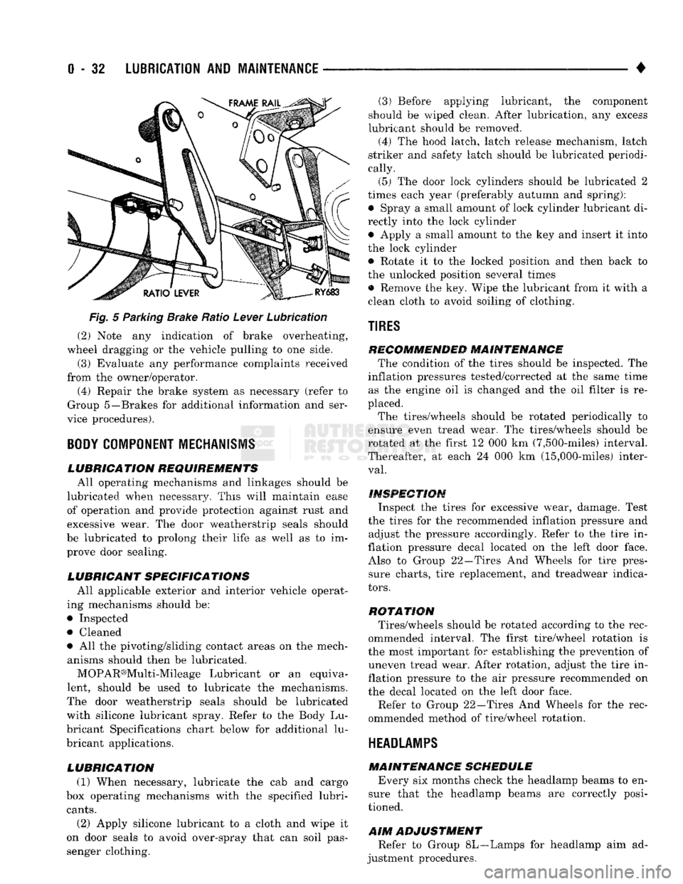
PARKING
BRAKE
LUBRICATION
The pivot and sliding contact areas of the parking
brake ratio lever should be lubricated to maintain ease of operation (Fig. 5).
(1) Apply MOPAR®Spray White Lube or equiva
lent to the sliding contact areas.
(2) Lubricate the control lever pivot areas with en
gine oil.
PARKING
BRAKE
FUNCTIONAL
TEST
AND
INSPECTION
(1) Engage the parking brake pedal and then re
lease it. (2) Test it for smooth operation and vehicle-hold
ing capability.
(3) Inspect the parking brake cables for kinks,
fraying and a binding condition. (4) With the parking brake released, the rear
wheels should rotate without restriction. Adjust the
parking brake cable tension, if necessary.
(5) Repair any parking brake malfunctions.
BRAKE OPERATIONAL TEST (1) Drive the vehicle and test for proper brake ac
tion.
Page 51 of 1502
0
- 32
LUBRICATION
AND
MAINTENANCE
•
Fig.
5 Parking Brake Ratio Lever Lubrication (2) Note any indication of brake overheating,
wheel dragging or the vehicle pulling to one side.
(3) Evaluate any performance complaints received
from the owner/operator. (4) Repair the brake system as necessary (refer to
Group 5—Brakes for additional information and ser
vice procedures).
BODY
COMPONENT
MECHANISMS
LUBRICATION REQUIREMENTS
All operating mechanisms and linkages should be
lubricated when necessary. This will maintain ease of operation and provide protection against rust and
excessive wear. The door weatherstrip seals should
be lubricated to prolong their life as well as to im prove door sealing.
LUBRICANT SPECIFICATIONS
All applicable exterior and interior vehicle operat
ing mechanisms should be:
• Inspected • Cleaned
• All the pivoting/sliding contact areas on the mech anisms should then be lubricated.
MOPAR®Multi-Mileage Lubricant or an equiva
lent, should be used to lubricate the mechanisms.
The door weatherstrip seals should be lubricated
with silicone lubricant spray. Refer to the Body Lu
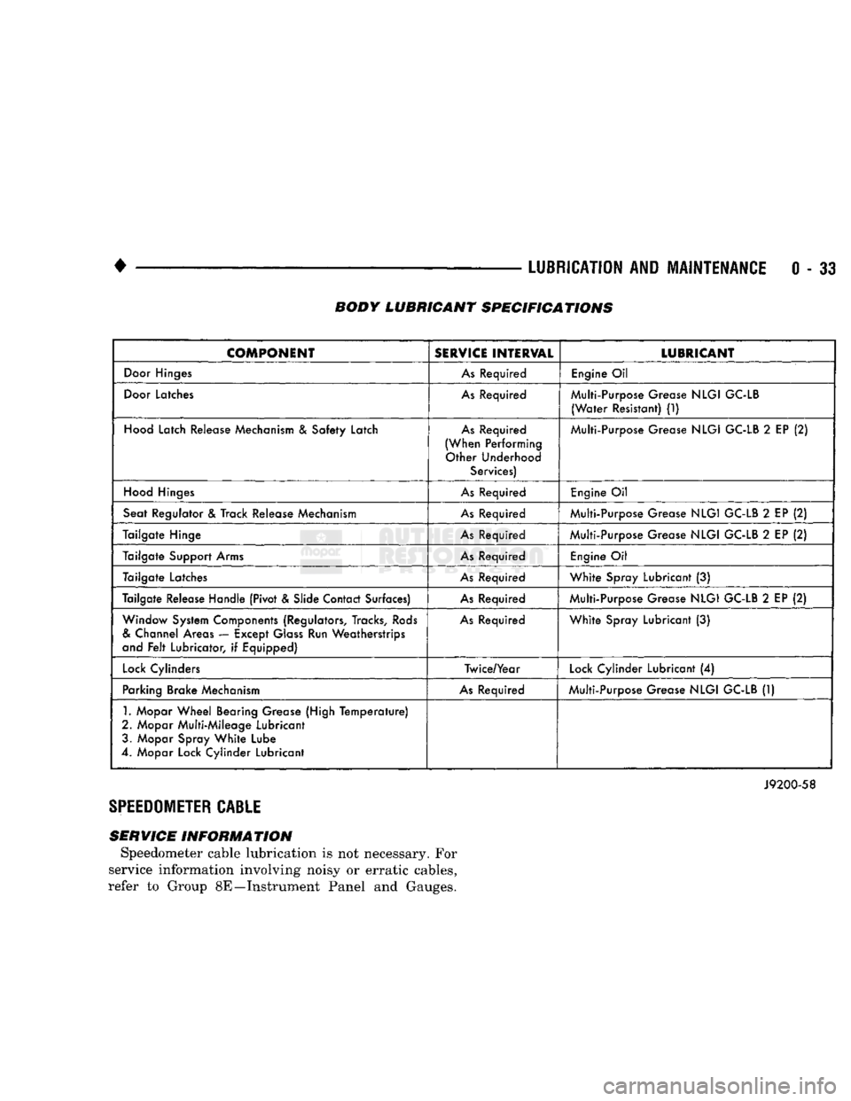
bricant Specifications chart below for additional lu
bricant applications.
LUBRICATION
(1) When necessary, lubricate the cab and cargo
box operating mechanisms with the specified lubri
cants.
(2) Apply silicone lubricant to a cloth and wipe it
on door seals to avoid over-spray that can soil pas
senger clothing. (3) Before applying lubricant, the component
should be wiped clean. After lubrication, any excess
lubricant should be removed.
(4) The hood latch, latch release mechanism, latch
striker and safety latch should be lubricated periodi
cally.
(5) The door lock cylinders should be lubricated 2
times each year (preferably autumn and spring): • Spray a small amount of lock cylinder lubricant di
rectly into the lock cylinder
• Apply a small amount to the key and insert it into
the lock cylinder • Rotate it to the locked position and then back to
the unlocked position several times
• Remove the key. Wipe the lubricant from it with a
clean cloth to avoid soiling of clothing.
TIRES
RECOMMENDED MAINTENANCE
The condition of the tires should be inspected. The
inflation pressures tested/corrected at the same time as the engine oil is changed and the oil filter is re
placed.
The tires/wheels should be rotated periodically to
ensure even tread wear. The tires/wheels should be
rotated at the first 12 000 km (7,500-miles) interval.
Thereafter, at each 24 000 km (15,000-miles) inter
val.
INSPECTION
Inspect the tires for excessive wear, damage. Test
the tires for the recommended inflation pressure and adjust the pressure accordingly. Refer to the tire in
flation pressure decal located on the left door face. Also to Group 22—Tires And Wheels for tire pressure charts, tire replacement, and treadwear indica
tors.
ROTATION
Tires/wheels should be rotated according to the rec
ommended interval. The first tire/wheel rotation is
the most important for establishing the prevention of uneven tread wear. After rotation, adjust the tire in
flation pressure to the air pressure recommended on
the decal located on the left door face.
Refer to Group 22—Tires And Wheels for the rec
ommended method of tire/wheel rotation.
HEADLAMPS
MAINTENANCE SCHEDULE
Every six months check the headlamp beams to en
sure that the headlamp beams are correctly posi
tioned.
AIM
ADJUSTMENT
Refer to Group 8L—Lamps for headlamp aim ad
justment procedures.
Page 52 of 1502
•
LUBRICATION
AND
MAINTENANCE
0 - 33 BODY LUBRICANT SPECIFICATIONS
COMPONENT
SERVICE
INTERVAL
LUBRICANT
Door
Hinges
As
Required
Engine
Oil
Door
Latches
As
Required Multi-Purpose Grease
NLGI
GC-LB
(Water
Resistant)
(1)
Hood
Latch Release Mechanism
&
Safety Latch
As
Required
(When Performing Other Underhood Services) Multi-Purpose Grease
NLGI
GC-LB
2
EP
(2)
Hood
Hinges
As
Required
Engine
Oil
Seat Regulator
&
Track Release Mechanism
As
Required Multi-Purpose Grease
NLGI
GC-LB
2
EP
(2)
Tailgate Hinge
As
Required Multi-Purpose Grease
NLGI
GC-LB
2
EP
(2)
Tailgate Support Arms
As
Required
Engine
Oil
Tailgate Latches
As
Required
White
Spray Lubricant
(3)
Tailgate Release Handle (Pivot & Slide Contact Surfaces)
As
Required Multi-Purpose Grease
NLGI
GC-LB
2
EP
(2)
Window System Components (Regulators, Tracks,
Rods
&
Channel Areas — Except
Glass
Run Weatherstrips
and
Felt
Lubricator,
if
Equipped)
As
Required
White
Spray Lubricant
(3)
Lock
Cylinders Twice/Year
Lock
Cylinder Lubricant
(4)
Parking Brake Mechanism
As
Required Multi-Purpose Grease
NLGI
GC-LB
(1)
1.
Mopar
Wheel
Bearing Grease (High
Temperature)
2. Mopar Multi-Mileage Lubricant 3. Mopar Spray
White
Lube
4. Mopar Lock Cylinder Lubricant
J9200-58
SPEEDOMETER
CABLE
SERVICE INFORMATION Speedometer cable lubrication is not necessary. For
service information involving noisy or erratic cables,
refer to Group 8E—Instrument Panel and Gauges.
Page 143 of 1502
3
- 14
REAR SUSPENSION
AND
AXLE
3
- 18
REAR SUSPENSION Fig.
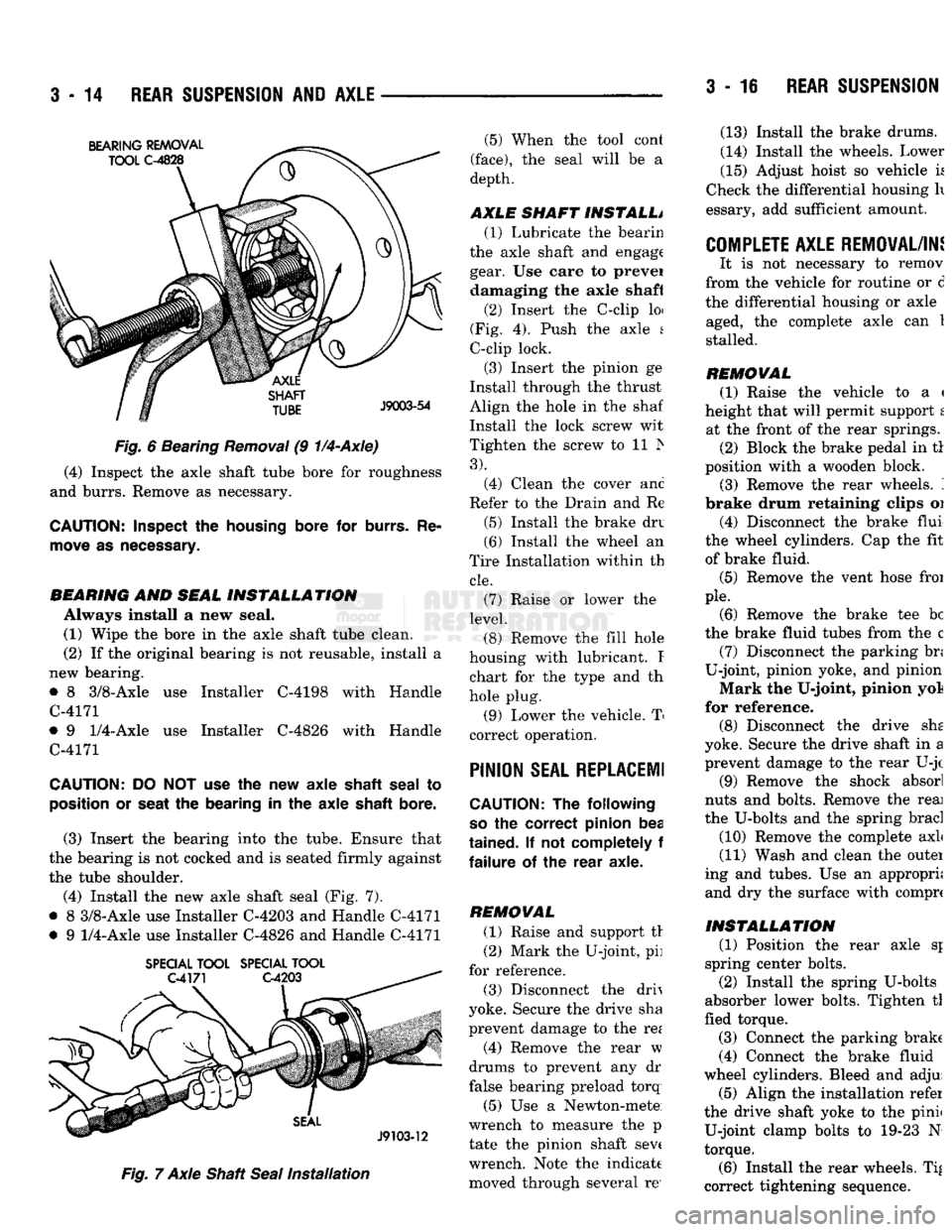
6 Bearing
Removal
(9
1/4-Axle)
(4) Inspect the axle shaft tube bore for roughness
and burrs. Remove as necessary.
CAUTION:
Inspect
the
housing
bore for
burrs.
Re
move
as
necessary.
BEARING
AND
SEAL
INSTALLATION
Always install a new seal. (1) Wipe the bore in the axle shaft tube clean.
(2) If the original bearing is not reusable, install a
new bearing.
• 8 3/8-Axle use Installer C-4198 with Handle
C-4171
• 9
1/4-Axle
use Installer C-4826 with Handle
C-4171
CAUTION:
DO NOT use the new axle
shaft
seal
to
position
or
seat
the bearing in the axle
shaft
bore.
(3) Insert the bearing into the tube. Ensure that
the bearing is not cocked and is seated firmly against
the tube shoulder.
(4) Install the new axle shaft seal (Fig. 7).
• 8 3/8-Axle use Installer C-4203 and Handle C-4171
• 9
1/4-Axle
use Installer C-4826 and Handle C-4171
SPECIAL
TOOL
SPECIAL
TOOL
Fig.
7 Axle Shaft
Seal
Installation
(5) When the tool cont
(face),
the seal will be a
depth.
AXLE SHAFT INSTALL* (1) Lubricate the bearin
the axle shaft and engage gear. Use care to prevei damaging the axle shaft
(2) Insert the C-clip loi
(Fig. 4). Push the axle s
C-clip lock.
(3) Insert the pinion ge
Install through the thrust
Align the hole in the shaf
Install the lock screw wit
Tighten the screw to 11 Is
3).
(4) Clean the cover anc
Refer to the Drain and Re
(5) Install the brake drv
(6) Install the wheel an
Tire Installation within th
cle.
(7) Raise or lower the
level.
(8) Remove the fill hole
housing with lubricant. I chart for the type and th
hole plug.
(9) Lower the vehicle. T
correct operation.
PINION
SEAL REPLACE!!
CAUTION:
The following
so
the correct pinion bea
tained.
If not completely f
failure
of the rear axle.
REMOVAL (1) Raise and support tr
(2) Mark the U-joint, pi]
for reference.
(3) Disconnect the drh
yoke. Secure the drive sha
prevent damage to the re*
(4) Remove the rear w
drums to prevent any dr
false bearing preload torq
(5) Use a Newton-mete
wrench to measure the p
tate the pinion shaft sev( wrench. Note the indicate moved through several re' (13) Install the brake drums.
(14) Install the wheels. Lower
(15) Adjust hoist so vehicle k
Check the differential housing h
essary, add sufficient amount.
COMPLETE AXLE REMOVAL/IN!
It is not necessary to remov
from the vehicle for routine or d
the differential housing or axle aged, the complete axle can 1
stalled.
REMOVAL (1) Raise the vehicle to a <
height that will permit support t at the front of the rear springs. (2) Block the brake pedal in tl
position with a wooden block. (3) Remove the rear wheels. '.
brake drum retaining clips oi
(4) Disconnect the brake flui
the wheel cylinders. Cap the fit of brake fluid.
(5) Remove the vent hose froi
pie.
(6) Remove the brake tee be
the brake fluid tubes from the c (7) Disconnect the parking bn
U-joint, pinion yoke, and pinion
Mark the U-joint, pinion yol
for reference. (8) Disconnect the drive she
yoke. Secure the drive shaft in a prevent damage to the rear U-jc
(9) Remove the shock absorl
nuts and bolts. Remove the reai
the U-bolts and the spring brad
(10) Remove the complete axL
(11) Wash and clean the outei
ing and tubes. Use an appropri; and dry the surface with comprc
INSTALLATION
(1) Position the rear axle sj
spring center bolts.
(2) Install the spring U-bolts
absorber lower bolts. Tighten tl
fled torque.
(3) Connect the parking brake
(4) Connect the brake fluid
wheel cylinders. Bleed and adjui (5) Align the installation refer
the drive shaft yoke to the pinii U-joint clamp bolts to 19-23 N
torque.
(6) Install the rear wheels. Ti|
correct tightening sequence.