1993 DODGE TRUCK torque
[x] Cancel search: torquePage 3 of 1502

FOREWORD
The information contained in this service manual has been prepared for the professional automotive tech
nician involved in daily repair operations. This manual does not cover theory of operation, which is addressed in service training material. Information describing the operation and use of standard and optional equipment
is included in the Owner's Manual provided with the vehicle.
Information in this manual is divided into groups. These groups contain general information, diagnosis,
testing, adjustments, removal, installation, disassembly, and assembly procedures for the components.
The Component and System Index of this manual identifies the correct group for the component or system
to be serviced. In addition, a Service Manual Comment form is included at the rear of this manual. Use the form to provide Chrysler Corporation with your comments and suggestions.
To assist in locating a group title page, use the Group Tab Locator on the following page. The solid bar
after the group title is aligned to a solid tab on the first page of each group. The first page of the group has
a contents section that lists major topics within the group.
Tightening torques are provided as a specific value throughout this manual. This value represents the
midpoint of the acceptable engineering torque range for a given fastener application. These torque values are
intended for use in service assembly and installation procedures using the correct OEM fasteners. When re
placing fasteners, always use the same type (part number) fastener as removed.
Chrysler Corporation reserves the right to change testing procedures, specifications, diagnosis, repair
methods, or vehicle wiring at any time without prior notice or incurring obligation.
NOTE: The acronyms, terminology and nomenclature used to identify emissions related components in
this manual may have changed from prior publications. These new terms are in compliance with S.A.E.
recommended practice J1930. This terminology standard (J1930) is required to comply with the 1993 California Air Research Board (CARB) requirements.
Page 6 of 1502
INTRODUCTION
INTRODUCTION
DESIGNATIONS,
LABELS/PLATES/DECALS,
CODES
AND DIMENSIONS/WEIGHTS .
CONTENTS
page
MEASUREMENT
AND TORQUE
... 1 SPECIFICATIONS
page
. 11
DESIGNATIONS, LABELS/PLATES/DECALS, CODES
AND
DIMENSIONS/WEIGHTS
INDEX
page
Engine
and
Transmission/Transfer
Case
Identification
2
Engine/Transmission/GVWR
4
Equipment
Identification
Plate
3
International
Vehicle Control
and
Display
Symbols
10
Major Component
Identification 3
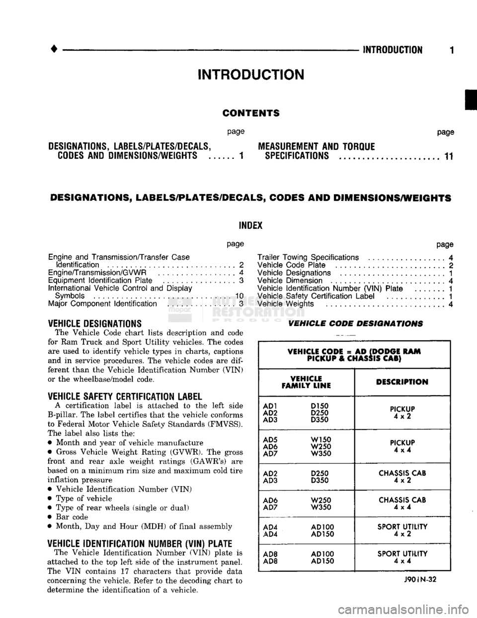
VEHICLE DESIGNATIONS The Vehicle Code chart lists description and code
for Ram Truck and Sport Utility vehicles. The codes are used to identify vehicle types in charts, captions
and in service procedures. The vehicle codes are
dif
ferent than the Vehicle Identification Number (VIN) or the wheelbase/model code.
VEHICLE SAFETY CERTIFICATION
LABEL
A certification label is attached to the left side
B-pillar. The label certifies that the vehicle conforms
to Federal Motor Vehicle Safety Standards (FMVSS).
The label also lists the: • Month and year of vehicle manufacture
• Gross Vehicle Weight Rating (GVWR). The gross
front and rear axle weight ratings (GAWR's) are
based on a minimum rim size and maximum cold tire inflation pressure Vehicle Identification Number (VIN)
Type of vehicle
Type of rear wheels (single or dual) Bar code
Month, Day and Hour (MDH) of final assembly
VEHICLE IDENTIFICATION NUMBER (VIN) PLATE The Vehicle Identification Number (VIN) plate is
attached to the top left side of the instrument panel.
The VIN contains 17 characters that provide data
concerning the vehicle. Refer to the decoding chart to
determine the identification of a vehicle.
page
Trailer
Towing Specifications
4
Vehicle Code Plate
2
Vehicle Designations
1
Vehicle Dimension
4
Vehicle
Identification
Number (VIN) Plate
1
Vehicle Safety
Certification
Label
............. 1
Vehicle Weights
4
VEHICLE CODE
DESIGNATIONS
VEHICLE CODE
= AD
(DODGE
RAM
PICKUP
&
CHASSIS
CAB)
VEHICLE
FAMILY LINE DESCRIPTION
AD1
D150
AD2
D250
AD3
D350
PICKUP
4x2
AD5
W150
AD6
W250
AD7
W350
PICKUP
4x4
AD2
D250
AD3
D350
CHASSIS
CAB
4x2
AD6
W250
AD7
W350
CHASSIS
CAB
4x4
AD4
AD100
AD4
AD150
SPORT
UTILITY
4x2
AD8
AD100
AD8 AD
150
SPORT
UTILITY
4x4
J90IN-32
Page 16 of 1502
•
INTRODUCTION
11
MEASUREMENT
AND
TORQUE SPECIFICATIONS
INDEX
page
Metric
and
English/SAE
Conversion
11
Specification
Notations
11
SPECIFICATION NOTATIONS
WARNING:
THE USE OF
INCORRECT
ATTACHING
HARDWARE
CAN
RESULT
IN
COMPONENT
DAM
AGE
AND/OR
PERSONAL
INJURY.
It is important to retain the original attaching
hardware for assembly of the components. If the at
taching hardware is not reusable, hardware with
equivalent specifications must be used.
METRIC
AND
ENGLISH/SAE
CONVERSION
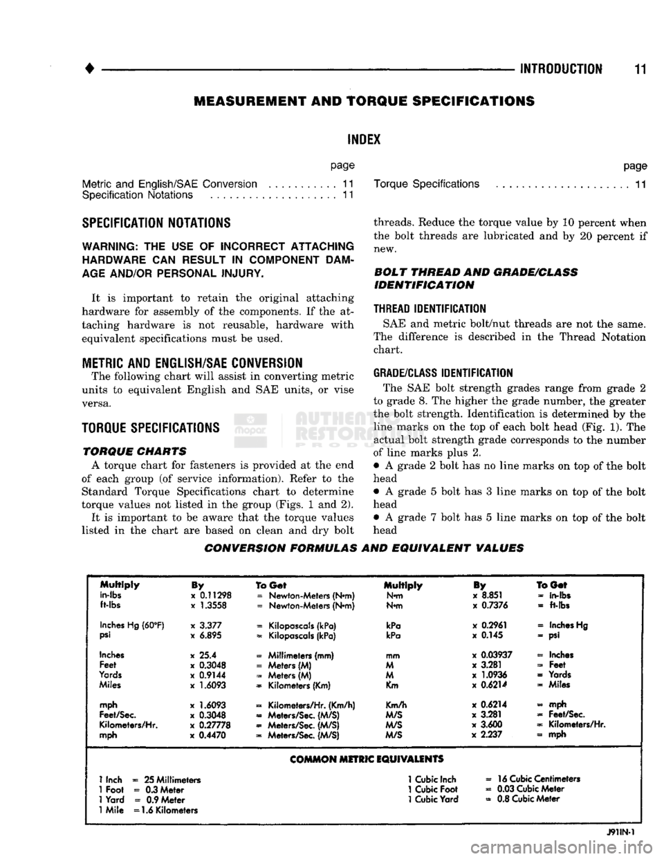
The following chart will assist in converting metric
units to equivalent English and SAE units, or vise versa.
TORQUE SPECIFICATIONS
TORQUE
CHARTS
A torque chart for fasteners is provided at the end
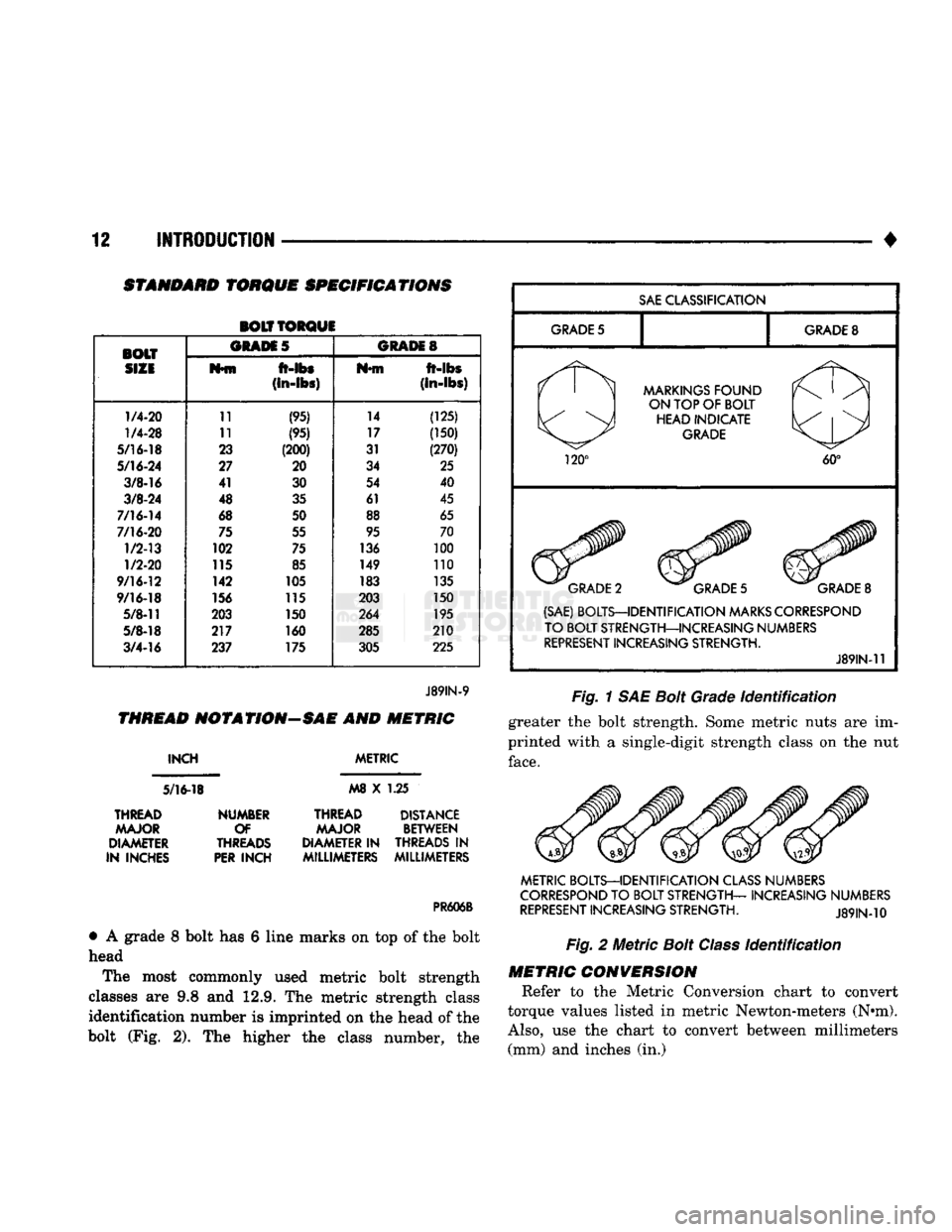
of each group (of service information). Refer to the Standard Torque Specifications chart to determine
torque values not listed in the group (Figs. 1 and 2).
It is important to be aware that the torque values
listed in the chart are based on clean and dry bolt
page
Torque Specifications
11
threads. Reduce the torque value by 10 percent when the bolt threads are lubricated and by 20 percent if new.
BOLT
THREAD
AND
GRADE/CLASS
IDENTIFICATION
THREAD
IDENTIFICATION
SAE and metric bolt/nut threads are not the same.
The difference is described in the Thread Notation chart.
GRADE/CLASS
IDENTIFICATION
The SAE bolt strength grades range from grade 2
to grade 8. The higher the grade number, the greater
the bolt strength. Identification is determined by the line marks on the top of each bolt head (Fig. 1). The
actual bolt strength grade corresponds to the number
of line marks plus 2.
• A grade 2 bolt has no line marks on top of the bolt
head
• A grade 5 bolt has 3 line marks on top of the bolt
head • A grade 7 bolt has 5 line marks on top of the bolt
head
CONVERSION FORMULAS
AND
EQUIVALENT
VALUES
Multiply
in-lbs
ft-lbs
By
x
0.11298
x
1.3558
To
Get
=
Newton-Meters (N*m)
=
Newton-Meters (N*m) Multiply
N*m
iy
x
8.851
x
0.7376
BGef
-
in-fbs
-
ft-lbs
Inches
Hg
(60°F)
psi
x
3.377
x
6.895
=
Kilopascals
(kPa)
=
Kilopascals
(kPa)
kPa
kPa
x
0.2961
x
0.145
«
Inches
Hg
- psi
Inches
Feet
Yards
Miles
x 25.4
x
0.3048
x
0.9144
x
1.6093
« Millimeters (mm)
=
Meters (M)
-
Meters (M)
=
Kilometers (Km) mm
M
M
Km
x
0.03937
x
3.281
x
1.0936
x
0.6214
« Inches
-
Feet
=
Yards « Miles
mph
Feet/Sec.
Kilometers/Hr.
mph
x
1.6093
x
0.3048
x
0.27778
x
0.4470
=
Kilometers/Hr. (Km/h)
«
Meters/Sec.
(M/S)
«
Meters/Sec.
(M/S)
=
Meters/Sec.
(M/S)
Km/h
M/S
M/S
M/S
x
0.6214
x
3.281
x
3.600
x
2.237 - mph
=
Feet/Sec.
=
Kilometers/Hr.
» mph
COMMON
MITRIC
EQUIVALENTS
1
Inch
=
25 Millimeters
1
Cubic
Inch
»
16
Cubic
Centimeters
1
Foot
-
0.3 Meter
1
Cubic
Foot
«
0.03
Cubic
Meter
1
Yard
=
0.9 Meter
1
Cubic
Yard
=
0.8
Cubic
Meter
1
Mile =1.6 Kilometers
J91IN-1
Page 17 of 1502
12
INTRODUCTION
STANDARD
TORQUE
SPECIFICATIONS
BOLT TORQUE
BOLT ORAM
5
GRADES
SIZE
M*fn
ft-lbs
Nfft
ft-abs
(in-lbs)
(In-lbs)
1/4-20
11
(95) 14
(125)
1/4-28
11 (95) 17 (150)
5/16-18
23 (200) 31 (270)
5/16-24
27 20 34 25
3/8-16
41
30 54
40
3/8-24
48 35 61 45
7/16-14
68
50 88 65
7/16-20
75 55 95 70
1/2-13
102
75 136 100
1/2-20
115 85 149 110
9/16-12
142
105 183 135
9/16-18
156 115 203 150
5/8-11
203 150 264 195
5/8-18
217 160 285 210
3/4-16
237 175
305 225
J89IN-9
THREAD
NOT A
TION—SAE
AND
METRIC
INCH
5/16-18
METRIC
M8
X 1.25
THREAD MAJOR
DIAMETER
IN INCHES NUMBER
OF
THREADS
PER
INCH
THREAD DISTANCE
MAJOR BETWEEN
DIAMETER IN THREADS
IN
MILLIMETERS MILLIMETERS
PR606B
•
A grade 8 bolt has 6 line marks on top of the bolt
head
The most commonly used metric bolt strength
classes are 9.8 and 12.9. The metric strength class identification number is imprinted on the head of the
bolt (Fig. 2). The higher the class number, the
SAE
CLASSIFICATION
GRADE
5
GRADE
8
MARKINGS
FOUND
ON TOP OF BOLT HEAD INDICATE
GRADE
120°
60°
GRADE
2
GRADE
5
GRADE
8
(SAE) BOLTS—IDENTIFICATION
MARKS
CORRESPOND
TO BOLT STRENGTH—INCREASING NUMBERS
REPRESENT
INCREASING STRENGTH.
J89IN-11
Fig.
1 SAE
Bolt
Grade
Identification
greater the bolt strength. Some metric nuts are im
printed with a single-digit strength class on the nut
face.
METRIC BOLTS—IDENTIFICATION
CLASS
NUMBERS
CORRESPOND
TO BOLT STRENGTH— INCREASING NUMBERS
REPRESENT
INCREASING STRENGTH.
J89IN-10
Fig.
2
Metric
Bolt
Class
Identification
METRIC
CONVERSION
Refer to the Metric Conversion chart to convert
torque values listed in metric Newton-meters (N»m).
Also,
use the chart to convert between millimeters (mm) and inches (in.)
Page 38 of 1502

•
LUBRICATION
AND
MAINTENANCE
0 - 19 ETBE— This fuel is a mixture of unleaded gasoline
and up to 17 percent ETBE (Ethyl Tertiary Butyl
Ether).
Unleaded gasoline blended with ETBE is ac ceptable.
METHANOL—Do not use unleaded gasoline
blended with methanol. The use of this type of alco hol can result in engine performance and damage to
critical components. Engine problems that result
from the use of methanol possibly will not be covered by the new vehicle warranty.
Certain brands of unleaded gasoline contain a per
centage of unidentified alcohol. These types of un
leaded gasoline are not recommended.
ADDITIVES MIXED
WITH
GASOLINE
Use of fuel system cleaning additives should be
avoided. Many of these solutions could contain highly
active solvents. This type of solvent can be harmful
to the gasket and diaphragm material within the fuel system.
DIESEL
ENGINE FUEL REQUIREMENTS
All Diesel engines normally can use number 2D
Diesel fuel for most year-round operations. A fuel
conforming to ASTM Specification D-975 is recom
mended. For extreme cold-weather operation (below
-18°C/0°F), or for prolonged cold-climate operation ei
ther:
• Use No. ID fuel, or
• Add an equal quantity of kerosene to No. 2D fuel (a 50/50 mixture).
Both methods provide protection against fuel gel
ling and waxing.
Diesel fuel seldom is without water contamination.
To help prevent fuel system malfunctions, drain all accumulated water from the separators periodically.
VACUUM OPERATED,
EMISSION
CONTROL
COMPONENTS
MAINTENANCE SCHEDULE
The following emission controls should be replaced
at the interval specified in the maintenance sched
ule:
• Bi-level purge check valves
• Delay valves
• Heated air temperature sensor (HATS)
• Air cleaner vacuum motors
EXHAUST
GAS RECIRCULATION (EGR)
SYSTEM
MAINTENANCE SCHEDULE
Replace the EGR valve and tube, and clean the
passages at the interval specified in maintenance schedule. If necessary, refer to Group 25—Emission
Control Systems for additional information.
OXYGEN
(02)
SENSOR
MAINTENANCE SCHEDULE
Replace the 02 sensor at the interval specified in
maintenance schedule.
IGNITION
CABLES,
DISTRIBUTOR CAP AND
ROTOR
MAINTENANCE SCHEDULE
Replace the ignition cables, distributor cap, and ro
tor at the interval specified in maintenance schedule.
Inspect the distributor for excessive wear and re
place, as necessary. Refer to Group 8D—Ignition Sys
tems for additional information.
IGNITION TIMING
MAINTENANCE SCHEDULE
Test and adjust, if necessary, the ignition timing at
the interval specified in maintenance schedule. Refer
to the specifications listed on the engine Emission Control Information label. Refer to Group 8D—Igni
tion Systems and to Group 25—Emission Control Systems for additional service information.
SPARK
PLUGS MAINTENANCE SCHEDULE
Replace the spark plugs at the interval specified in
maintenance schedule. Refer to the Spark Plugs
chart below and to Group 8D—Ignition Systems for additional service information.
SPARK
PLUGS
ENGINE
SPARK
PLUG
SPARK
PLUG
GAP
TORQUE
3.9L
5.2L
5.9L
RN12YC
RN12YC
RN12YC
0.9 mm
(0.035
in.)
0.9 mm
(0.035
in.)
0.9 mm
(0.035
in.) 41 N*m (30 ft. lb.)
41 NVn (30 ft. lb.)
41 N*m (30 ft. lb.)
J9100-17
BATTERY
MAINTENANCE SCHEDULE
Replace battery at interval specified in mainte
nance schedule.
Page 43 of 1502
0
- 24
LUBRICATION
AND
MAINTENANCE
•
CAUTION:
Do not
overfill
the
transmission.
(9) Adjust
the
level
of the ATF
accordingly.
It
is
important
to use the
correct fluid
in an
automatic transmission. MOPAR®ATF PLUS
(ATF Type
7176)
should
be
used. Dexron®
II
ATF
can be
used
if the
recommended fluid
is not
available,
(10) Insert
the
dipstick into
the
tube.
DRAIN, FILTER CHANGE, BAND ADJUSTMENT AND REFILL
The chart below lists
the
intervals
at
which
the
transmission should
be
serviced. Also, refer
to the
Fluid Capacities chart
for
fill capacity.
AUTOMATIC TRANSMISSION SERVICE
IN-
TERVALS
Normal
Usage
Light
Duty
Cycle
60 000
km
37,500
miles
Heavy
Duty
Cycle
38
000 km 24,000
miles
Severe
Usage
19 000 km 12,000
miles
J9100-19
It
is
very important
to use the
correct fluid
in
an automatic transmission. MOPAR®ATF PLUS
(ATF Type
7176)
should
be
used.
An
equivalent
Dexron®
II ATF
could
be
used only
if the
recom
mended fluid
is not
available.
The torque converter does
not
have
a
drain plug.
No attempt should
be
made
to
drain
the
converter.
Refer
to
Group
21
—Transmissions
for
transmission
drain
and
refill procedures.
TRANSFER
CASE
(4WD
VEHICLES)
INSPECTION The NP205
and
NP241 transfer cases fluid level
should
be
checked whenever maintenance
is
neces
sary under
the
vehicle.
FLUID
LEVEL
The vehicle must
be
level when
the
fluid level
is checked.
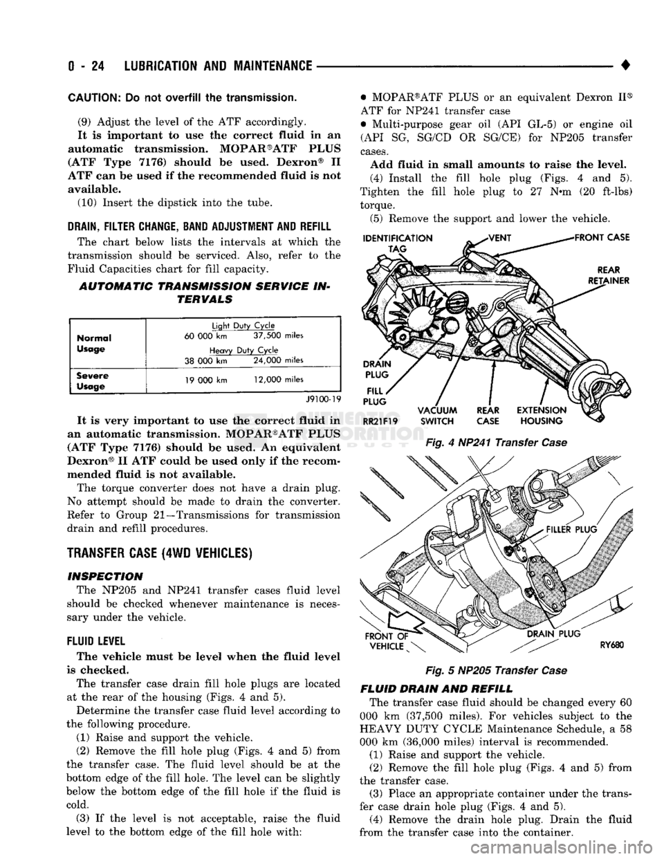
The transfer case drain fill hole plugs
are
located
at
the
rear
of the
housing (Figs.
4 and 5).
Determine
the
transfer case fluid level according
to
the following procedure.
(1) Raise
and
support
the
vehicle.
(2) Remove
the
fill hole plug (Figs.
4 and 5)
from
the transfer case.
The
fluid level should
be at the
bottom edge
of the
fill hole.
The
level
can be
slightly
below
the
bottom edge
of the
fill hole
if the
fluid
is
cold.
(3)
If the
level
is not
acceptable, raise
the
fluid
level
to the
bottom edge
of the
fill hole with: • MOPAR®ATF PLUS
or an
equivalent Dexron
II®
ATF
for
NP241 transfer case
• Multi-purpose gear
oil (API GL-5) or
engine
oil
(API
SG,
SG/CD
OR
SG/CE)
for
NP205 transfer
cases.
Add fluid
in
small amounts
to
raise
the
level. (4) Install
the
fill hole plug (Figs.
4 and 5).
Tighten
the
fill hole plug
to 27 N-m (20
ft-lbs) torque.
(5) Remove
the
support
and
lower
the
vehicle.
Fig.
4
HP241 Transfer
Case
Fig.
5
NP205 Transfer
Case
FLUID DRAIN
AND
REFILL The transfer case fluid should
be
changed every
60
000
km
(37,500 miles).
For
vehicles subject
to the
HEAVY DUTY CYCLE Maintenance Schedule,
a 58
000
km
(36,000 miles) interval
is
recommended.
(1) Raise
and
support
the
vehicle.
(2) Remove
the
fill hole plug (Figs.
4 and 5)
from
the transfer case. (3) Place
an
appropriate container under
the
trans
fer case drain hole plug (Figs.
4 and 5).
(4) Remove
the
drain hole plug. Drain
the
fluid
from
the
transfer case into
the
container.
Page 44 of 1502
•
LUBRICATION
AND
MAINTENANCE
0 - 25
CAUTION:
Do not
over-tighten
the
drain
and fill
hole
plugs.
Over-tightening
can strip the
hole
threads
and/or crack
the
aluminum housing.
(5) Install the drain hole plug (Figs. 4 and 5) in
the transfer case. Tighten the drain hole plug to 27 N*m (20 ft-lbs) torque. (6) Fill the transfer case to the bottom edge of the
fill hole (Figs. 4 and 5) with: • MOPAR®ATF PLUS or an equivalent Dexron II®
ATF for NP241 transfer cases
• Multi-purpose gear oil (API GL-5) or engine oil (API SG, SG/CD or SG/CE) for NP205 transfer cases. (7) Install the fill hole plug (Figs. 4 and 5) in the
transfer case. Tighten the plug to 27 N«m (20 ft-lbs) torque.
(8) Remove the support and lower the vehicle.
FLUID SPECIFICATION
• MOPAR®ATF PLUS or an equivalent Dexron II®
ATF for NP241 transfer cases • Multi-purpose gear oil (API GL-5) or engine oil (API SG, SG/CD or SG/CE) for NP205 transfer cases
NP20I
MULTI-PURPOSE GEAR OIL/ENGINE
OIL
SELECTION
MULTI-PURPOSE GEAR OIL-if the anticipated
minimum temperature will: • Be above 32°C (90°F)-use SAE 140, API GL-5;
• Decrease to as low as -23°C (-10°F)-use SAE 90,
API GL-5; and • Be below -23°C (-10°F)-use SAE 80, API GL-5. ENGINE OIL—if the anticipated minimum tem
perature will be: ® Above 0°C (32°F)-use SAE 50, API SG, SG/CD or
SG/CE;
• Below 0°C (32°F)-use SAE 30, API SG, SG/CD or SG/CE.
SHIFT MECHANISM-NP241 AND NP205 The transfer case shift mechanism should be
cleaned and lubricated as necessary.
Lubricate the pivot, the sliding contact areas and
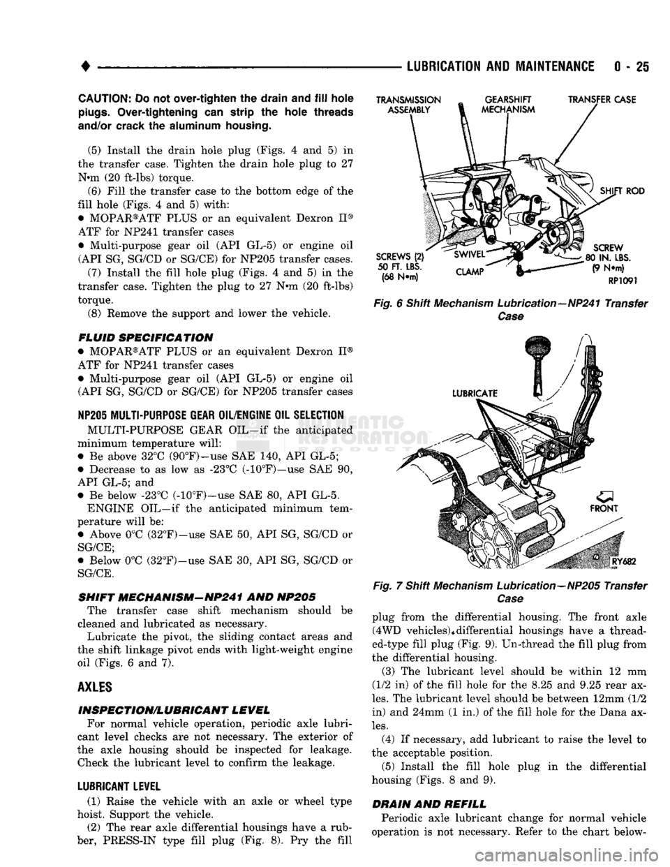
the shift linkage pivot ends with light-weight engine oil (Figs. 6 and 7).
AXLES
INSPECTION/LUBRICANT LEVEL For normal vehicle operation, periodic axle lubri
cant level checks are not necessary. The exterior of
the axle housing should be inspected for leakage. Check the lubricant level to confirm the leakage.
LUBRICANT LEVEL
(1) Raise the vehicle with an axle or wheel type
hoist. Support the vehicle.
(2) The rear axle differential housings have a rub
ber, PRESS-IN type fill plug (Fig. 8). Pry the fill
TRANSMISSION
ASSEMBLY
GEARSHIFT
MECHANISM TRANSFER CASE
SCREWS
(2)
50
FT. LBS.
(68 N*m)
CLAMP
SHIFT
ROD
SCREW
80 IN.
LBS.
(9 N*m)
RP1091
Fig.
6 Shift
Mechanism
Lubrication—NP241 Transfer
Case
Fig.
RY682
7 Shift
Mechanism
Lubrication—NP205 Transfer
Case
plug from the differential housing. The front axle (4WD vehicles)*differential housings have a thread
ed-type fill plug (Fig. 9). Un-thread the fill plug from
the differential housing.
(3) The lubricant level should be within 12 mm
(1/2 in) of the fill hole for the 8.25 and 9.25 rear ax
les.
The lubricant level should be between 12mm (1/2
in) and 24mm (1 in.) of the fill hole for the Dana ax
les.
(4) If necessary, add lubricant to raise the level to
the acceptable position.
(5) Install the fill hole plug in the differential
housing (Figs. 8 and 9).
DRAIN
AND
REFILL
Periodic axle lubricant change for normal vehicle
operation is not necessary. Refer to the chart below-
Page 48 of 1502
•
LUBRICATION
AND
MAINTENANCE
0 - 29
POWER STEERING SYSTEM
SERVICE SCHEDULE
FLUID
LEWEL
WARNING.
THE
POWER
STEERING
FLUID LEVEL
SHOULD
ALWAYS
BE
CHECKED
WITH THE EN
GINE
OFF TO
PREVENT
PERSONAL
INJURY.
The power steering fluid should be checked when
ever the engine is being serviced for other reasons. Clean the outside of the cap before removing. The
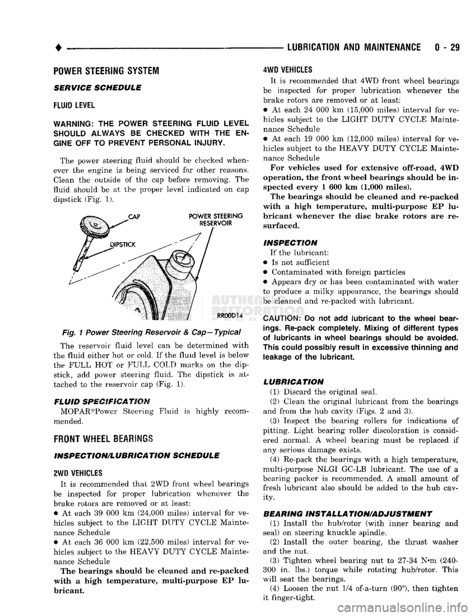
fluid should be at the proper level indicated on cap dipstick (Fig. 1).
Fig.
1
Power
Steering Reservoir & Cap—Typical
The reservoir fluid level can be determined with
the fluid either hot or cold. If the fluid level is below
the FULL HOT or FULL COLD marks on the dip stick, add power steering fluid. The dipstick is at
tached to the reservoir cap (Fig. 1).
FLUID SPECIFICATION MOPAR03)Power Steering Fluid is highly recom
mended.
FRONT
WHEEL BEARINGS
INSPECTION/LUBRICATION SCHEDULE
2WD
VEHICLES
It is recommended that 2WD front wheel bearings
be inspected for proper lubrication whenever the
brake rotors are removed or at least: • At each 39 000 km (24,000 miles) interval for ve
hicles subject to the LIGHT DUTY CYCLE Mainte nance Schedule • At each 36 000 km (22,500 miles) interval for ve
hicles subject to the HEAVY DUTY CYCLE Mainte nance Schedule The bearings should be cleaned and re-packed
with a high temperature, multi-purpose EP lu
bricant.
4WD
VEHICLES
It is recommended that 4WD front wheel bearings
be inspected for proper lubrication whenever the
brake rotors are removed or at least:
• At each 24 000 km (15,000 miles) interval for ve
hicles subject to the LIGHT DUTY CYCLE Mainte nance Schedule
• At each 19 000 km (12,000 miles) interval for ve
hicles subject to the HEAVY DUTY CYCLE Mainte nance Schedule
For vehicles used for extensive off-road, 4WD
operation, the front wheel bearings should be in spected every 1 600 km (1,000 miles).
The bearings should be cleaned and re-packed
with a high temperature, multi-purpose EP lu
bricant whenever the disc brake rotors are re surfaced.
INSPECTION If the lubricant:
• Is not sufficient
• Contaminated with foreign particles
• Appears dry or has been contaminated with water
to produce a milky appearance, the bearings should
be cleaned and re-packed with lubricant.
CAUTION:
Do not add
lubricant
to the
wheel
bear
ings.
Re-pack completely. Mixing
of
different
types
of lubricants
in
wheel
bearings should
be
avoided.
This could possibly result
in
excessive thinning
and
leakage
of the
lubricant.
LUBRICATION (1) Discard the original seal.
(2) Clean the original lubricant from the bearings
and from the hub cavity (Figs. 2 and 3).
(3) Inspect the bearing rollers for indications of
pitting. Light bearing roller discoloration is consid ered normal. A wheel bearing must be replaced if any serious damage exists.
(4) Re-pack the bearings with a high temperature,
multi-purpose NLGI GC-LB lubricant. The use of a
bearing packer is recommended. A small amount of fresh lubricant also should be added to the hub cav ity.
BEARING INSTALLA TION/ADJUSTMENT (1) Install the hub/rotor (with inner bearing and
seal) on steering knuckle spindle.
(2) Install the outer bearing, the thrust washer
and the nut.
(3) Tighten wheel bearing nut to 27-34 N^m (240-
300 in. lbs.) torque while rotating hub/rotor. This
will seat the bearings.
(4) Loosen the nut 1/4 of-a-turn (90°), then tighten
it finger-tight.